

PendoTECH PMAT3, PMAT2P, PMAT3A, PMAT4R, PMAT2F User Manual
...
PressureMAT™
System User Guide
Revision 8
www.pendotech.com
PressureMAT User Guide
WARNING: DANGEROUS VOLTAGE INSIDE THE CONTROL BOX.
REPRESENTATIVE. NO USER SERVICEABLE PARTS INSIDE.
WARNING: POTENTIAL SHOCK HAZARD. UNLESS PROPERLY PANEL
CORD AND WHERE THE POWER CORD WILL NOT BE DAMAGED.
Revision 8
PressureMAT System User Guide
Model PMAT2
Model PMAT2P
Model PMAT3
Model PMAT3P
Model PMAT4A
Model PMAT4R
Model PMAT3A
Model PMAT2A
Model PMAT2F
Model PMAT2HR
Model PMAT-S
Model PMAT-SHR
All rights reserved. No part of this publication may be reproduced, sto red in an electronic retrieval system, or transmitted,
in any for m or by any means , whether electronic, mechanical, by photo copying, or otherwis e, without the written consent
of PendoTECH.
The infor mation in this User Guide is believed to be accurate and reliable for use and operation of the control system,
however, PendoTECH assumes no responsibility for the use of this product except for what is covered in the Limited
Warranty and Terms and Condition of Sale.
PressureMAT is a Trademark of PendoTECH Copyright © 2010 -2014, PendoTECH
Used throughout this guide:
WARNING: “WARNING” is used to indicate the presence of a hazard which can cause severe
personal injury, death, or substantial property damage if the warning is ignored.
Note: “Note” is used to notify the user of installation or operation information which is
important but not hazard related.
CONTROL BOX ONLY TO BE OPENED BY PENDOTECH OR AUTHORIZED
MOUNTED, DO NOT USE THIS PRODUCT NEAR WATER OR IF YOU ARE
WET. DO NOT SUBMERGE THIS PRODUCT. USE ONLY IN A GROUNDED
ELECTRICAL OUTLET. UNLESS PROPERLY PANEL MOUNTED, UNPLUG
THE PRODUCT FROM THE OUTLET BEFORE CLEANING WITH ANY
LIQUIDS. INSTALL SECURELY ON A STABLE SURFACE. INSTALL IN A
LOCATION WHERE NO ONE CAN STEP ON OR TRIP OVER THE POWER
WARNING: GOODS AND SOFTWARE ARE NOT DESIGNED, INTENDED OR AUTHORIZED FOR USE AS
COMPONENTS IN LIFE SUPPOR T OR MEDICAL DEVICES. THEY ARE NOT DESIGNED FOR ANY
APPLICATION IN WHICH THE FAILURE OF THE PRODUCT COULD RESU LT IN PERSONAL INJURY,
DEATH OR PROPERTY DAMAGE.
Page 2/48

PressureMAT User Guide
Revision 8
Table of Contents
1. Overview of PendoTECH PressureMAT................................................................................ 4
1.2. Instrument Details .................................................................................................................... 5
1.2.1. Hardware Details ................................................................................................................. 6
1.2.2. Software Details ................................................................................................................. 13
2. Setup and Use of the System ................................................................................................ 23
2.1. System Setup* ........................................................................................................................ 23
2.2. Using the System* ................................................................................................................. 24
3. Flow Meter Function in PressureMAT-PLUS (2P, 3P & 2F) .............................................. 25
3.1. Display ................................................................................................................................... 25
3.2. Back Panel ............................................................................................................................. 25
3.3. Connection to Back Panel ...................................................................................................... 26
3.4. Navigation in the Flow Meter Input Channel ........................................................................ 26
4. Analog Input Function in PressureMAT-PLUS (2P, 3A & 2A only)................................... 30
4.1. Display ................................................................................................................................... 30
4.2. Back Panel ............................................................................................................................. 30
4.3. Connection to Back Panel ...................................................................................................... 31
4.4. Navigation in the Analog Input Channel ............................................................................... 31
5. Cable Information ................................................................................................................. 34
5.1. Cable for Pressure Inputs ....................................................................................................... 34
APPENDIX A: PRODUCT WARRANTY ................................................................................. 35
APPENDIX B: PendoTECH Single Use Pressure Sensors ......................................................... 36
APPENDIX C: PressureMAT Data Acquisition Software .......................................................... 37
APPENDIX D: Panel Mount of System ...................................................................................... 39
APPENDIX E: EC Declaration of Conformity ........................................................................... 41
APPENDIX F: Pinch Valve Box Accessory (PDKT-PVE) ........................................................ 42
APPENDIX G: Using the PressureMAT with WinWedge Software .......................................... 44
APPENDIX H: PressureMAT Smoothing Function (PV Filter) ................................................. 45
Page 3/48

PressureMAT User Guide
Model Number
Number of
Inputs
Number of
Outputs
Outputs
PMAT2* 2 4
2 Relays / 2 Analogs or 4 Relays
PMAT2P
2 pressure/1
flow/1 analog
4
4 Analogs [may be re-configured]
PMAT3 3 4
3 Analogs / 1 Relay (for all sensors)
PMAT3P
3 pressure/1 flow
4
4 Analogs [may be re-configured]
PMAT4A 4 4
4 Analogs
PMAT4R 4 4
4 Relays
PMAT3A
3 pressure/
1 analog
4
4 Analogs [may be re-configured]
PMAT2A
2 pressure/
2 analog
4
4 Analogs [may be re-configured]
PMAT2F
2 pressure/
2 flow
4
4 Analogs [may be re-configured]
PMAT-S* 1 3
1 Relay /1 Analog / 1 remote tare
Revision 8
1. Overview of PendoTECH PressureMAT
The PressureMAT is a monitor, alarm, and transmitter system designed for use with Single Use
Pressure Sensors from PendoTECH. It is comprised of the control system box with user interface and
the connectors on the back panel where input and output components can be interfaced. If equipped,
the alarm output function includes a dry contact relay output. The transmitter function delivers an
analog 4 – 20 milliamp output signal corresponding to the pressure reading on the display. There are
numerous applications in biopharmaceutical production processes where the system can be used.
The models are as follows:
* Available in “High Resolution” model with HR s uffix
System Components Su ppl ied:
• PressureMAT Instrument
• Cable(s) for connection of pressure sensors to the control system
• Connectors for cable for each output
• 4 Screws for mounting
• Power supply
Options:
• PMAT-STND Benchtop St and
• PMAT-GUI PressureMAT Data Acquisition Software (Appendix C)
• PDKTP-RS232U RS-232 cable for data output to a PC via USB
• PMAT-PANEL Panel mount kit (Appendix D)
• PMAT-WALL4 Wall mount stainless steel box
• PDKT-650-298CVR Pressure sensor cable dust cover / zero simulator for PressureMAT
• PressureMAT Carts – contact PendoTECH for details
1.1. PressureMAT Instrument
Page 4/48

PressureMAT User Guide
Benchtop Stand
Wall Mount Stainless Steel Box
Revision 8
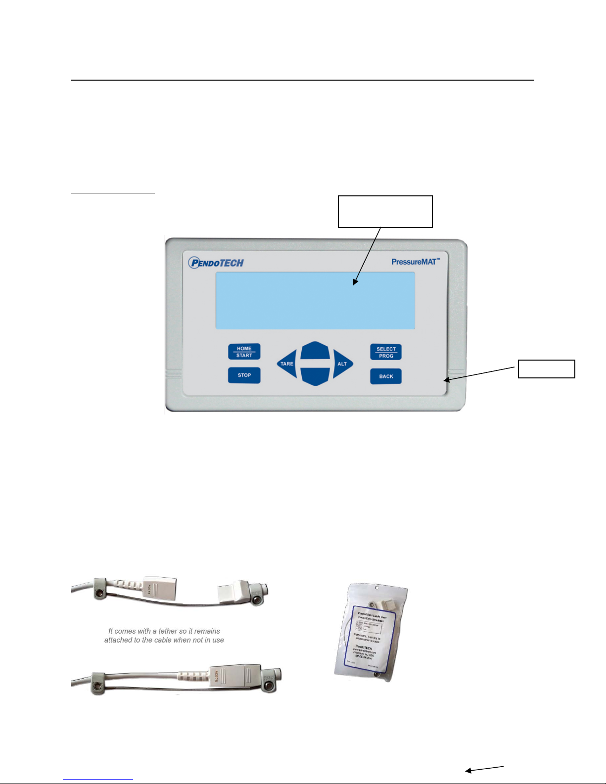
The PressureMAT with its user interface is used to display pressure readings, zero calibrate the
pressure sensor, and to access the program menus to edit the alarm high and low set point values and
other tasks.
The sensor pressure is displayed on the LCD display for each input channel. High and low alarm
pressure set points are entered on the keypad for each channel and if the process pressure goes below
the low setting or above the high setting, the system will go into alarm state. With models with the
relay output, the alarm function includes activation of the dry contact relay output, a flashing
“ALARM>” indication on LCD on the same line as the pressure input channel in the alarm state, and
an audible tone for 30 seconds. When an alarm condition goes away, all indicators automatically go
back to normal (unless the optional alarm latching function is turned on which requires STOP to be
pressed to clear the alarm). The alarm functions are always active for all channels. For the
PressureMAT PLUS models, flow or a scaled analog input value can measure & display other values.
Also available is a single channel model PMAT-S:
The model has a unique remote pressure tare input.
Some available options:
1.2. Instrument Details
Page 5/48
PressureMAT User Guide
LCD BACKLIT
DISPLAY
KEYPAD
Revision 8
1.2.1. Hardware Details
There is no power switch so the system cannot be accidentally turned off. When the wall power
supply is connected to the system and plugged into a wall outlet, the system will turn ON. Instructions
to power down the system without unplugging are in Section 1.2.2 (System Power). The Front and
Back Panels details are as shown:
FRONT PANEL:
Note: If a pressure sensor is not connected or is disconnected during operation of the system,
the pressure reading will drift and eventually go to a value greater than 75psi/5.17 bar and an
alarm condition will occur. The time until the high alarm occurs may vary and this feature
should not be used to control a process due to the time variance. Associated relays will switch
and the analog output will send greater than 20mA.
The Sensor Cable Dust Cover / Zero Simulator for PressureMAT (PDKT-650-298CVR) can be used
to:
1) Maintain a zero pressure when a channel is not in use
2) Protect the pins on the re-usable cable
Page 6/48
PressureMAT User Guide
Revision 8
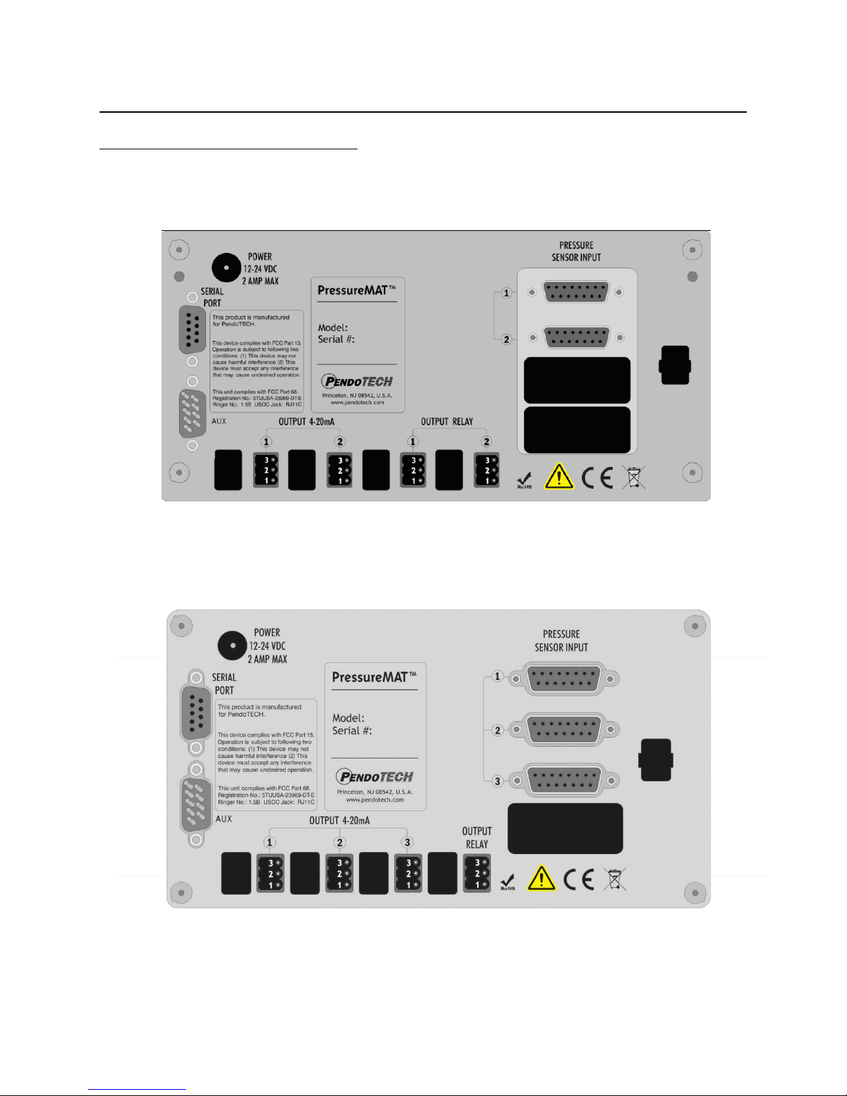
BACK PANEL CONFIGURATIONS:
PMAT2- Two Input Unit (two relays, one for each channel;4-20mA for each channel):
PMAT3- Three Input Unit:
Page 7/48
PressureMAT User Guide
Revision 8
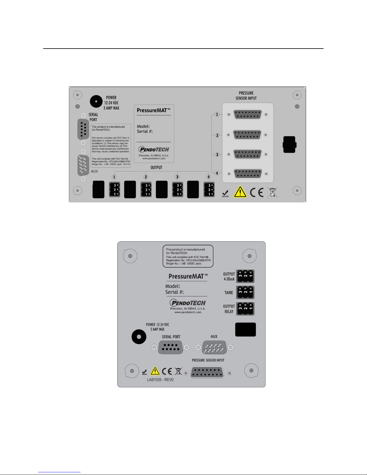
PMAT4x- Four Input Unit (If 4R outputs are relays; if 4A, outputs are 4-20mA):
PMAT-S - One Input Unit:
NOTE: The PMAT2P, PMAT3P, PMAT3A, PMAT2A, and PMAT2F back panel schematics
are shown in Section 3
Page 8/48
PressureMAT User Guide
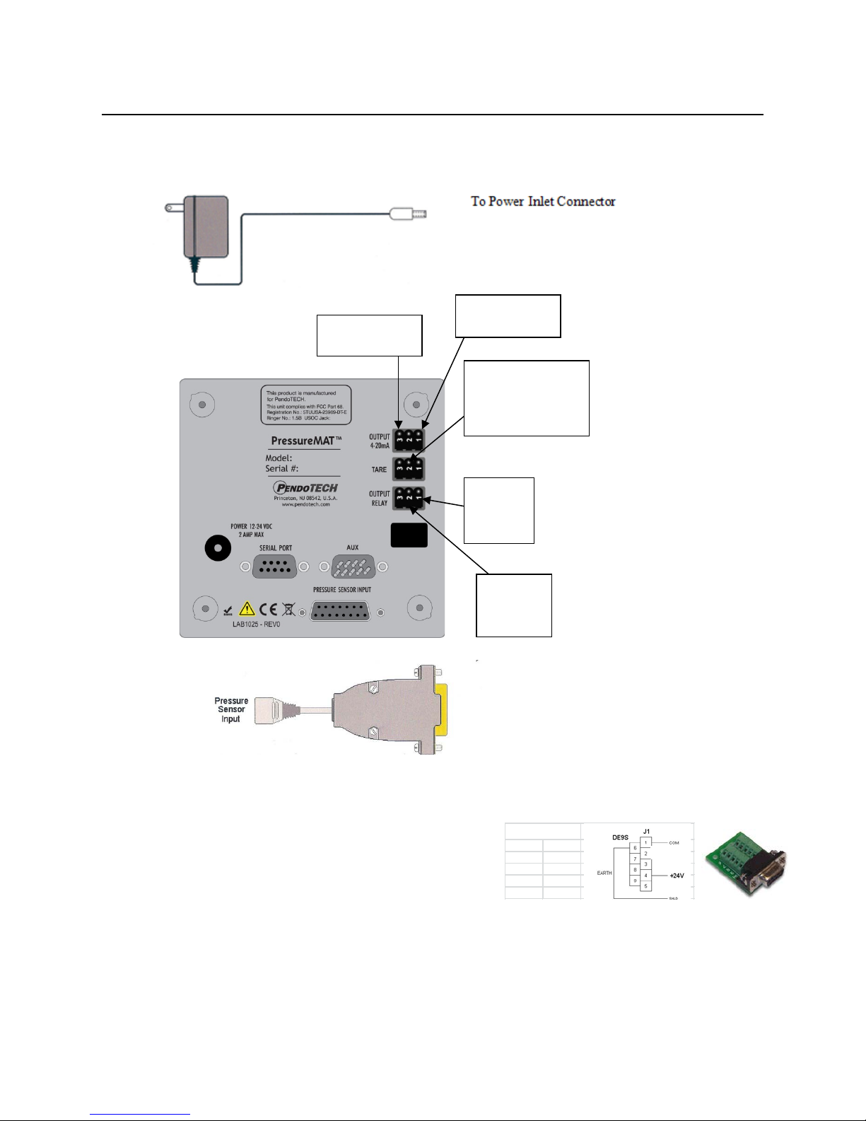
To Power Inlet Connector
Wire here
CLOSED
Wire here
Revision 8
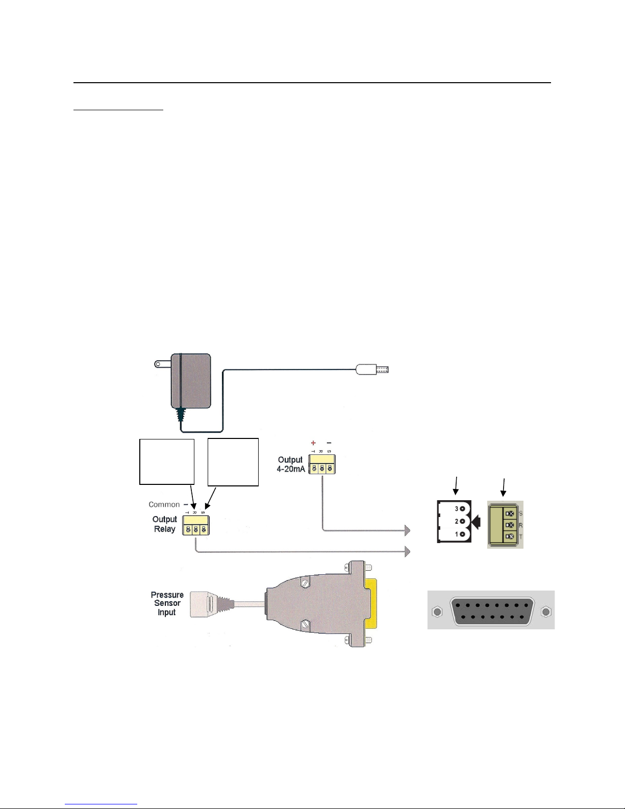
CONNECTIONS:
The external connections to the back panel are as shown below.
1. POWER SUPPLY connected to the power inlet connector
2. The PRESSURE SENSOR INPUTS connected via a DB15 connector
3. The OUTPUT RELAY:
a. NORMALLY OPEN- wired to terminals S and T via supplied connector (will switch to
CLOSED position with alarm condition)
b. NORMALLY CLOSED- wired to terminals R and T via supplied connector (will
switch to OPEN position with alarm condition)
c. POWER REMOVED- OPEN (S and T position) is the condition for relay(s)
4. The 4-20mA ANALOG OUTPUTS are wired to terminals S and T via supplied connector as
shown
5. Serial Port- send data RS232 to be collected by an external device (such as a PC)
6. Auxiliary input- alternate power input connection for panel mounting
7. Tare (S model only)- external relay (dry contact) closure across pins will tare sensor to zero
External Cable Connections to Back Panel for Multi-channel Units
for
Normally
for
Normally
OPEN
___________________
Panel Connector
_____________________
DB15
Page 9/48

PressureMAT User Guide
Power Wiring
Signal DB9
+12-24V D
4
Common 1
Revision 8
Power Inlet to Auxiliary (AUX) Connector (for panel mount): r
Page 10/48
PressureMAT User Guide
Power Wiring
Signal DB9
+12-24V D
4
Common 1
Pin 2 for
Pin1 for
Pin 3 is common
Pin 2 for Remote tare
command
Pin 1 for 4-20mA
Revision 8
External Cable Connections to Back Panel for PMAT-S Single Channel Unit
output signal (+)
on all connectors
input- a momentary
contact c lo sure is used
to create this input
Normally
OPEN
Normally
CLOSED
To Pressure Sensor Inputs(DB15)
Power Inlet to Auxiliary (AUX) Connector (for panel mount): r
Page 11/48

PressureMAT User Guide
Control System Component
Specifications
Enclosure
Multi-channel models PMAT-S:
NEMA 4X front panel
Environmental
Temperature: 0–55° C (32–132° F)
(warm up to rated accuracy = 6 min.)
Keypad
8 button keypad with LEXAN® overlay
Display
8 line LCD backlit blue- psi as XX.X and bar as X.XX
HR Models: X.XXpsi and bar as X.XXX
Power Inlet
2.5 mm Circular Power Jack (center post positive)
4 Watts (powered by supplied appropriate wall supply)
Pressure Sensor Inputs
Configured for PendoTECH Single Use Pressure Sensors*
Excitation voltage: 4.096V +/- 0.22%
Flow Meter Input
(2P, 2F and 3Ponly)
Input to measure 5V square wave frequency/pulse
Relay Output
• Normally OPEN or CLOSED via wiring
Screw terminal connector
Analog Outputs (4-20 mA)
Screw terminal connector
Load Impedance: Zero Ohm minimum resistance
Analog Input (4-20 mA)
(2P, 2A, and 3A only)
Screw terminal connector
4-20mA Range +/- 0.01% of full scale; 100 Ohms
Regulatory Compliances
CE Mark EN61326-1
FCC Part 68 5TUUSA-23969-DT-E
Revision 8
Specifications
H x W x D: 7.86” x 4.47” x 2.25” 4.70” x 4.70” x 2.25”
(19.96 x 11.35 x 5.72 cm) (11.94 x 11.94 x 5.72cm)
Approx: 1.43 lbs. (0.65 kgs) 0.86 lbs (0.39 kg)
Material: ABS Plastic
Panel/wall mount optional
Humidity: 0–95% RH non-condensing, Shipping/Storage:
–20° to +85° C
12-24 Volts DC
Connector on reusable cable: DB15
• 28 Volt AC/DC Maximum
• 1 amp closure, 2 amps maximum current
• 20 mS max turn on/off time
•
4-20mA Range: -10 to 75 psi (-0.69 bar to 5.17 bar)
HR Models: -1 to 3 psi (0.069 bar to 0.207 bar)
Accuracy: 0.1% of full scale
Sourcing w/Maximum Load: 400 Ohms
FCC Part 15 Class B verified
* See Appendix B for important information on this product
LEXAN® is a registered trademark of General Electric Company
Page 12/48
PressureMAT User Guide
> 1 Pressure . . . . . . 0.0 psi
0.0
2 Pressure . . . . . . 0.0 psi
Revision 8
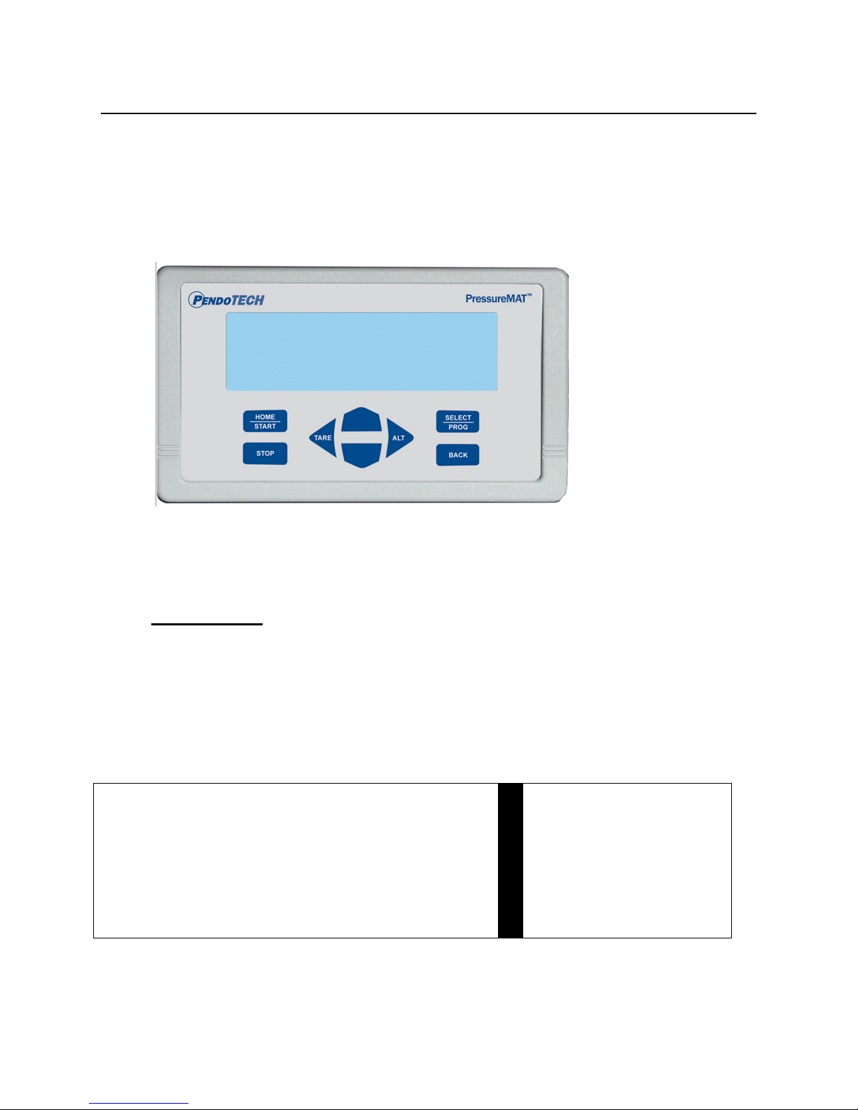
1.2.2. Software Details
The software interface consists of the keypad (shown below) and the 8 line LCD backlit
display. The program/firmware is stored in memory in the control system and cannot be edited
by users. Only settings in the software menus can be changed. The system does not store any
data unless equipped with optional data logger.
There is no power switch so the system cannot be accidentally turned off. When the wall
power supply is connected to the system and plugged into a wall outlet, the welcome screen
will appear momentarily followed by 2 beeps, then the HOME screen will appear.
Home Screen
When the system is powered on, the following HOME screen appears after the welcome screen
with pressures 1 through 4 shown depending on the model number
(with X.XX bar or XX.X psi as designated):
HOME Screen:
Multi-channel unit (PMAT4 shown with all 4 channels): PMAT-S
3 Pressure . . . . . . 0.0 psi
4 Pressure . . . . . . 0.0 psi
Pressure psi
NOTE: Number 3 and 4 Pressure readings are replaced by the flow values and analog input
values in the models PMAT2P, PMAT3P, PMAT3A, PMAT2A, and PMAT2F. Back panel
schematics are shown in Section 3. Different models and/or settings may show different number
of digits to the right of the decimal.
Page 13/48

PressureMAT User Guide
HOME/START
Dual Purpose:
2- Used to power on the system if turned off
STOP
Used to reset alarms (if optional alarm latching
turned ON)
TARE/LEFT ARROW
Dual Purpose:
when on the HOME screen
RIGHT ARROW/ALT
Used when in the program menu to scroll the cursor
right
UP ARROW
Three Purposes:
selected value
DOWN ARROW
Three Purposes:
selected value
SELECT/PROG
Used to enter the program menu for the selected
and save changes to a setting
BACK
Dual Purpose:
GLOBAL SETTINGS menu
Revision 8
Keypad
KEY
Function
1- Used to return to the HOME screen from the
program menus
1- Used when in the program menu to scroll
the cursor left
2- Zero pressure sensor of selected channel
1- When on the HOME screen used to select
different input channels
2- In the program menus, used to select
different sub-menus
3- Within a program menu, used to change a
1- When on the HOME screen used to select
different input channels
2- In the program menus, used to select
different sub-menus
3- Within a program menu, used to change a
channel or for the selected menu; used to confirm
1- Used to return to the previous screen when
in a program menu
2- Can be pressed three times to access the
Page 14/48

PressureMAT User Guide
Channel X
> Input Viewing
Revision 8
Navigation Between Pressure Sensor Input Channels
At the HOME screen, the UP/DOWN arrows are used to change the selected pressure input
channel.
Zero Calibration for Pressure Sensors
1. Select the desired input channel using the UP/DOWN buttons
2. With a pressure sensor connected to the system and EXPOSED ONLY TO
ATMOSPHERIC PRESSURE, press the Tare Button (LEFT ARROW button) on the
keypad
3. The display should read 0.0 psi / 0.00 bar
4. If 0.0 psi / 0.00 bar is not displayed, press the ZERO/TARE button on the keypad again
Note: a minus sign may appear on the display when it reads 0.0 psi / 0.00 bar; this is
normal as the pressure measured by the system may be a value such as -0.001 but
displayed as -0.0 psi / -0.00 bar.
Alarm Function
If any channel has an alarm set, the alarm function includes:
a. The display screen will blink “ALARM>” on the channel with the alarm
b. An audible tone for 30 seconds during the present alarm (it is reset for a new alarm
condition)
c. If present, a dry contact relay associated with that channel will switch (i.e., if wired as
normally CLOSED, it will OPEN; if wired as normally OPEN, it will CLOSE)
When an alarm condition goes away, all indicators automatically go back to normal (unless the
optional alarm latching function is turned on). If a sensor is inadvertently not connected or
becomes accidentally disconnected during a process the pressure reading will drift and
eventually go to a value greater than 75psi/5.17 bar and an alarm condition will occur if the
high alarm set-point is surpassed or in psi when the value goes above the hard-coded limit of
75. The time until the high alarm occurs may vary and this feature should not be used to
control a process due to the time variance. Associated relays will switch and the analog output
will send greater than 20mA.
Program M enu
To access the program menu for a pressure sensor, press the PROG key on the keypad with the
desired input channel selected. The program menu is mainly used for setting of the high and
low alarm set points and alarm detect delay. After pressing the PROG key, the following
screen appears with X indicating selected channel:
Output Viewing
Input Programming
Output Programming
Note: the PMAT-S menu selections are truncated due to space limitations on certain scre ens
Page 15/48
 Loading...