

Page 1

PressureMAT™
System User Guide
Revision 8
www.pendotech.com
Page 2
PressureMAT User Guide
WARNING: DANGEROUS VOLTAGE INSIDE THE CONTROL BOX.
REPRESENTATIVE. NO USER SERVICEABLE PARTS INSIDE.
WARNING: POTENTIAL SHOCK HAZARD. UNLESS PROPERLY PANEL
CORD AND WHERE THE POWER CORD WILL NOT BE DAMAGED.
Revision 8
PressureMAT System User Guide
Model PMAT2
Model PMAT2P
Model PMAT3
Model PMAT3P
Model PMAT4A
Model PMAT4R
Model PMAT3A
Model PMAT2A
Model PMAT2F
Model PMAT2HR
Model PMAT-S
Model PMAT-SHR
All rights reserved. No part of this publication may be reproduced, sto red in an electronic retrieval system, or transmitted,
in any for m or by any means , whether electronic, mechanical, by photo copying, or otherwis e, without the written consent
of PendoTECH.
The infor mation in this User Guide is believed to be accurate and reliable for use and operation of the control system,
however, PendoTECH assumes no responsibility for the use of this product except for what is covered in the Limited
Warranty and Terms and Condition of Sale.
PressureMAT is a Trademark of PendoTECH Copyright © 2010 -2014, PendoTECH
Used throughout this guide:
WARNING: “WARNING” is used to indicate the presence of a hazard which can cause severe
personal injury, death, or substantial property damage if the warning is ignored.
Note: “Note” is used to notify the user of installation or operation information which is
important but not hazard related.
CONTROL BOX ONLY TO BE OPENED BY PENDOTECH OR AUTHORIZED
MOUNTED, DO NOT USE THIS PRODUCT NEAR WATER OR IF YOU ARE
WET. DO NOT SUBMERGE THIS PRODUCT. USE ONLY IN A GROUNDED
ELECTRICAL OUTLET. UNLESS PROPERLY PANEL MOUNTED, UNPLUG
THE PRODUCT FROM THE OUTLET BEFORE CLEANING WITH ANY
LIQUIDS. INSTALL SECURELY ON A STABLE SURFACE. INSTALL IN A
LOCATION WHERE NO ONE CAN STEP ON OR TRIP OVER THE POWER
WARNING: GOODS AND SOFTWARE ARE NOT DESIGNED, INTENDED OR AUTHORIZED FOR USE AS
COMPONENTS IN LIFE SUPPOR T OR MEDICAL DEVICES. THEY ARE NOT DESIGNED FOR ANY
APPLICATION IN WHICH THE FAILURE OF THE PRODUCT COULD RESU LT IN PERSONAL INJURY,
DEATH OR PROPERTY DAMAGE.
Page 2/48
Page 3

PressureMAT User Guide
Revision 8
Table of Contents
1. Overview of PendoTECH PressureMAT................................................................................ 4
1.2. Instrument Details .................................................................................................................... 5
1.2.1. Hardware Details ................................................................................................................. 6
1.2.2. Software Details ................................................................................................................. 13
2. Setup and Use of the System ................................................................................................ 23
2.1. System Setup* ........................................................................................................................ 23
2.2. Using the System* ................................................................................................................. 24
3. Flow Meter Function in PressureMAT-PLUS (2P, 3P & 2F) .............................................. 25
3.1. Display ................................................................................................................................... 25
3.2. Back Panel ............................................................................................................................. 25
3.3. Connection to Back Panel ...................................................................................................... 26
3.4. Navigation in the Flow Meter Input Channel ........................................................................ 26
4. Analog Input Function in PressureMAT-PLUS (2P, 3A & 2A only)................................... 30
4.1. Display ................................................................................................................................... 30
4.2. Back Panel ............................................................................................................................. 30
4.3. Connection to Back Panel ...................................................................................................... 31
4.4. Navigation in the Analog Input Channel ............................................................................... 31
5. Cable Information ................................................................................................................. 34
5.1. Cable for Pressure Inputs ....................................................................................................... 34
APPENDIX A: PRODUCT WARRANTY ................................................................................. 35
APPENDIX B: PendoTECH Single Use Pressure Sensors ......................................................... 36
APPENDIX C: PressureMAT Data Acquisition Software .......................................................... 37
APPENDIX D: Panel Mount of System ...................................................................................... 39
APPENDIX E: EC Declaration of Conformity ........................................................................... 41
APPENDIX F: Pinch Valve Box Accessory (PDKT-PVE) ........................................................ 42
APPENDIX G: Using the PressureMAT with WinWedge Software .......................................... 44
APPENDIX H: PressureMAT Smoothing Function (PV Filter) ................................................. 45
Page 3/48
Page 4

PressureMAT User Guide
Model Number
Number of
Inputs
Number of
Outputs
Outputs
PMAT2* 2 4
2 Relays / 2 Analogs or 4 Relays
PMAT2P
2 pressure/1
flow/1 analog
4
4 Analogs [may be re-configured]
PMAT3 3 4
3 Analogs / 1 Relay (for all sensors)
PMAT3P
3 pressure/1 flow
4
4 Analogs [may be re-configured]
PMAT4A 4 4
4 Analogs
PMAT4R 4 4
4 Relays
PMAT3A
3 pressure/
1 analog
4
4 Analogs [may be re-configured]
PMAT2A
2 pressure/
2 analog
4
4 Analogs [may be re-configured]
PMAT2F
2 pressure/
2 flow
4
4 Analogs [may be re-configured]
PMAT-S* 1 3
1 Relay /1 Analog / 1 remote tare
Revision 8
1. Overview of PendoTECH PressureMAT
The PressureMAT is a monitor, alarm, and transmitter system designed for use with Single Use
Pressure Sensors from PendoTECH. It is comprised of the control system box with user interface and
the connectors on the back panel where input and output components can be interfaced. If equipped,
the alarm output function includes a dry contact relay output. The transmitter function delivers an
analog 4 – 20 milliamp output signal corresponding to the pressure reading on the display. There are
numerous applications in biopharmaceutical production processes where the system can be used.
The models are as follows:
* Available in “High Resolution” model with HR s uffix
System Components Su ppl ied:
• PressureMAT Instrument
• Cable(s) for connection of pressure sensors to the control system
• Connectors for cable for each output
• 4 Screws for mounting
• Power supply
Options:
• PMAT-STND Benchtop St and
• PMAT-GUI PressureMAT Data Acquisition Software (Appendix C)
• PDKTP-RS232U RS-232 cable for data output to a PC via USB
• PMAT-PANEL Panel mount kit (Appendix D)
• PMAT-WALL4 Wall mount stainless steel box
• PDKT-650-298CVR Pressure sensor cable dust cover / zero simulator for PressureMAT
• PressureMAT Carts – contact PendoTECH for details
1.1. PressureMAT Instrument
Page 4/48
Page 5

PressureMAT User Guide
Benchtop Stand
Wall Mount Stainless Steel Box
Revision 8
The PressureMAT with its user interface is used to display pressure readings, zero calibrate the
pressure sensor, and to access the program menus to edit the alarm high and low set point values and
other tasks.
The sensor pressure is displayed on the LCD display for each input channel. High and low alarm
pressure set points are entered on the keypad for each channel and if the process pressure goes below
the low setting or above the high setting, the system will go into alarm state. With models with the
relay output, the alarm function includes activation of the dry contact relay output, a flashing
“ALARM>” indication on LCD on the same line as the pressure input channel in the alarm state, and
an audible tone for 30 seconds. When an alarm condition goes away, all indicators automatically go
back to normal (unless the optional alarm latching function is turned on which requires STOP to be
pressed to clear the alarm). The alarm functions are always active for all channels. For the
PressureMAT PLUS models, flow or a scaled analog input value can measure & display other values.
Also available is a single channel model PMAT-S:
The model has a unique remote pressure tare input.
Some available options:
1.2. Instrument Details
Page 5/48
Page 6
PressureMAT User Guide
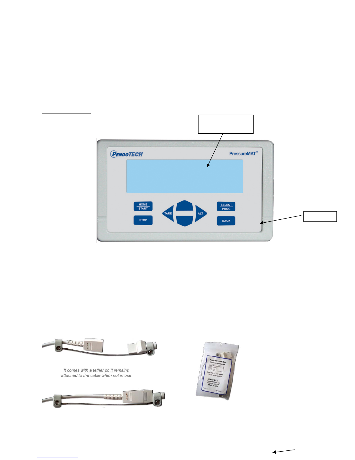
LCD BACKLIT
DISPLAY
KEYPAD
Revision 8
1.2.1. Hardware Details
There is no power switch so the system cannot be accidentally turned off. When the wall power
supply is connected to the system and plugged into a wall outlet, the system will turn ON. Instructions
to power down the system without unplugging are in Section 1.2.2 (System Power). The Front and
Back Panels details are as shown:
FRONT PANEL:
Note: If a pressure sensor is not connected or is disconnected during operation of the system,
the pressure reading will drift and eventually go to a value greater than 75psi/5.17 bar and an
alarm condition will occur. The time until the high alarm occurs may vary and this feature
should not be used to control a process due to the time variance. Associated relays will switch
and the analog output will send greater than 20mA.
The Sensor Cable Dust Cover / Zero Simulator for PressureMAT (PDKT-650-298CVR) can be used
to:
1) Maintain a zero pressure when a channel is not in use
2) Protect the pins on the re-usable cable
Page 6/48
Page 7
PressureMAT User Guide
Revision 8
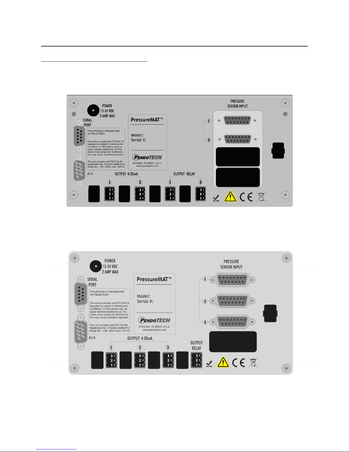
BACK PANEL CONFIGURATIONS:
PMAT2- Two Input Unit (two relays, one for each channel;4-20mA for each channel):
PMAT3- Three Input Unit:
Page 7/48
Page 8
PressureMAT User Guide
Revision 8
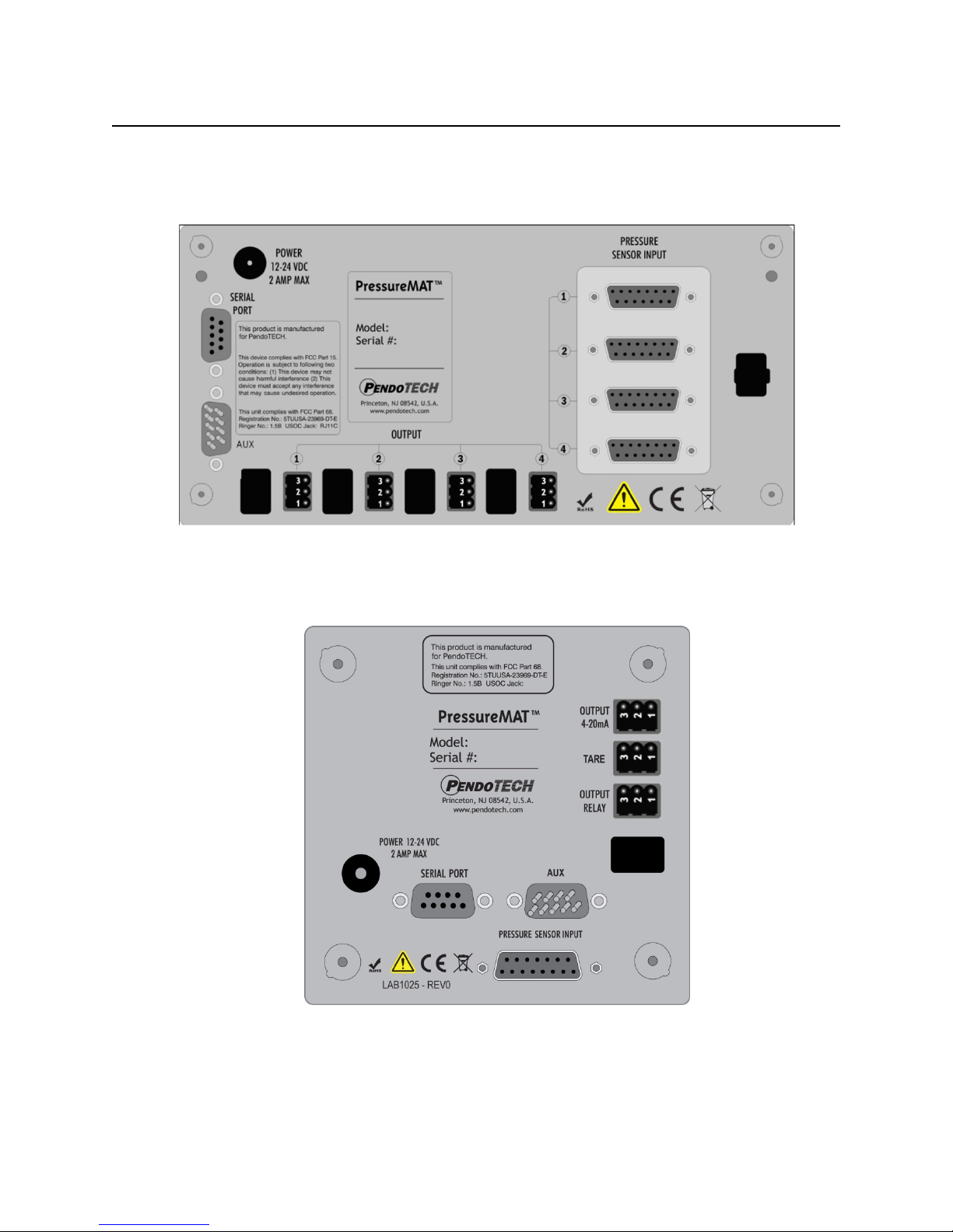
PMAT4x- Four Input Unit (If 4R outputs are relays; if 4A, outputs are 4-20mA):
PMAT-S - One Input Unit:
NOTE: The PMAT2P, PMAT3P, PMAT3A, PMAT2A, and PMAT2F back panel schematics
are shown in Section 3
Page 8/48
Page 9
PressureMAT User Guide
To Power Inlet Connector
Wire here
CLOSED
Wire here
Revision 8
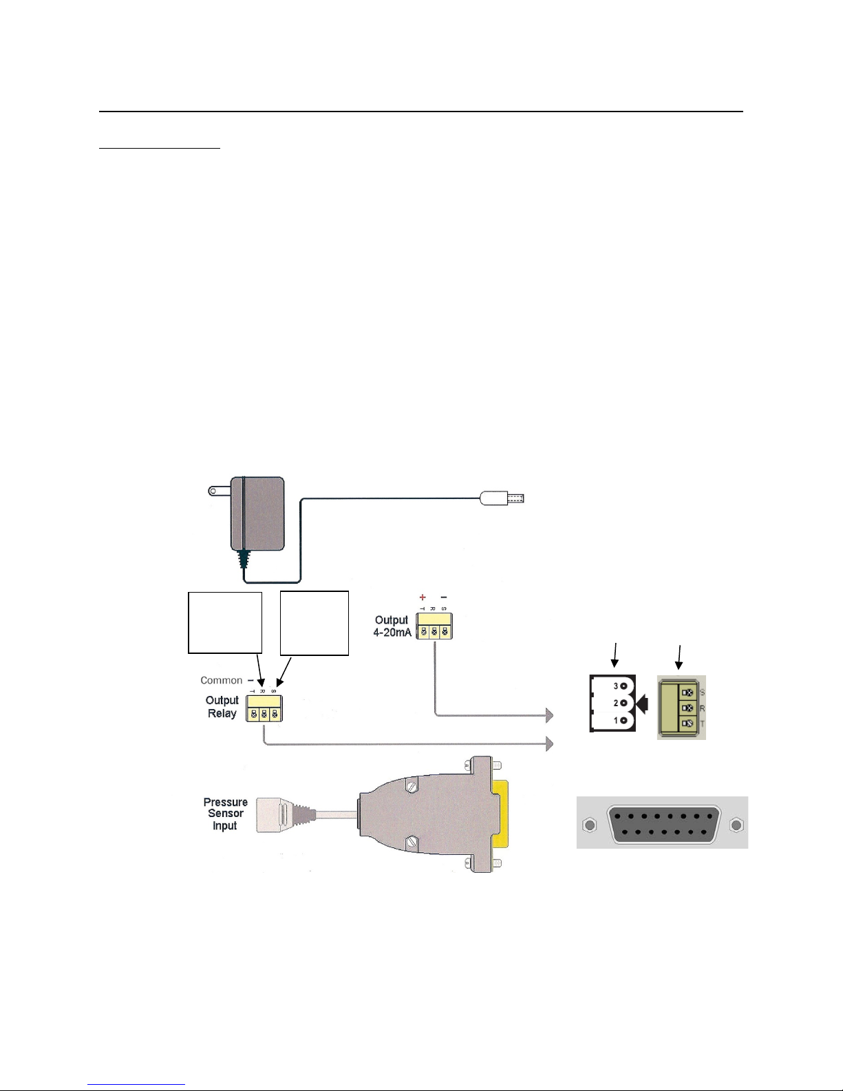
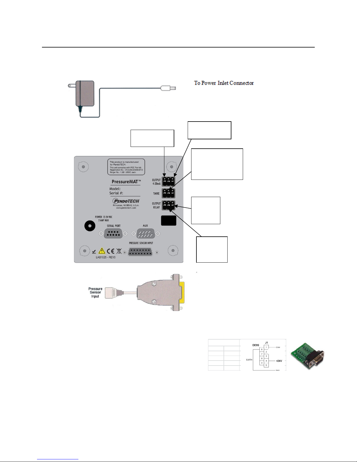
CONNECTIONS:
The external connections to the back panel are as shown below.
1. POWER SUPPLY connected to the power inlet connector
2. The PRESSURE SENSOR INPUTS connected via a DB15 connector
3. The OUTPUT RELAY:
a. NORMALLY OPEN- wired to terminals S and T via supplied connector (will switch to
CLOSED position with alarm condition)
b. NORMALLY CLOSED- wired to terminals R and T via supplied connector (will
switch to OPEN position with alarm condition)
c. POWER REMOVED- OPEN (S and T position) is the condition for relay(s)
4. The 4-20mA ANALOG OUTPUTS are wired to terminals S and T via supplied connector as
shown
5. Serial Port- send data RS232 to be collected by an external device (such as a PC)
6. Auxiliary input- alternate power input connection for panel mounting
7. Tare (S model only)- external relay (dry contact) closure across pins will tare sensor to zero
External Cable Connections to Back Panel for Multi-channel Units
for
Normally
for
Normally
OPEN
___________________
Panel Connector
_____________________
DB15
Page 9/48
Page 10

PressureMAT User Guide
Power Wiring
Signal DB9
+12-24V D
4
Common 1
Revision 8
Power Inlet to Auxiliary (AUX) Connector (for panel mount): r
Page 10/48
Page 11
PressureMAT User Guide
Power Wiring
Signal DB9
+12-24V D
4
Common 1
Pin 2 for
Pin1 for
Pin 3 is common
Pin 2 for Remote tare
command
Pin 1 for 4-20mA
Revision 8
External Cable Connections to Back Panel for PMAT-S Single Channel Unit
output signal (+)
on all connectors
input- a momentary
contact c lo sure is used
to create this input
Normally
OPEN
Normally
CLOSED
To Pressure Sensor Inputs(DB15)
Power Inlet to Auxiliary (AUX) Connector (for panel mount): r
Page 11/48
Page 12

PressureMAT User Guide
Control System Component
Specifications
Enclosure
Multi-channel models PMAT-S:
NEMA 4X front panel
Environmental
Temperature: 0–55° C (32–132° F)
(warm up to rated accuracy = 6 min.)
Keypad
8 button keypad with LEXAN® overlay
Display
8 line LCD backlit blue- psi as XX.X and bar as X.XX
HR Models: X.XXpsi and bar as X.XXX
Power Inlet
2.5 mm Circular Power Jack (center post positive)
4 Watts (powered by supplied appropriate wall supply)
Pressure Sensor Inputs
Configured for PendoTECH Single Use Pressure Sensors*
Excitation voltage: 4.096V +/- 0.22%
Flow Meter Input
(2P, 2F and 3Ponly)
Input to measure 5V square wave frequency/pulse
Relay Output
• Normally OPEN or CLOSED via wiring
Screw terminal connector
Analog Outputs (4-20 mA)
Screw terminal connector
Load Impedance: Zero Ohm minimum resistance
Analog Input (4-20 mA)
(2P, 2A, and 3A only)
Screw terminal connector
4-20mA Range +/- 0.01% of full scale; 100 Ohms
Regulatory Compliances
CE Mark EN61326-1
FCC Part 68 5TUUSA-23969-DT-E
Revision 8
Specifications
H x W x D: 7.86” x 4.47” x 2.25” 4.70” x 4.70” x 2.25”
(19.96 x 11.35 x 5.72 cm) (11.94 x 11.94 x 5.72cm)
Approx: 1.43 lbs. (0.65 kgs) 0.86 lbs (0.39 kg)
Material: ABS Plastic
Panel/wall mount optional
Humidity: 0–95% RH non-condensing, Shipping/Storage:
–20° to +85° C
12-24 Volts DC
Connector on reusable cable: DB15
• 28 Volt AC/DC Maximum
• 1 amp closure, 2 amps maximum current
• 20 mS max turn on/off time
•
4-20mA Range: -10 to 75 psi (-0.69 bar to 5.17 bar)
HR Models: -1 to 3 psi (0.069 bar to 0.207 bar)
Accuracy: 0.1% of full scale
Sourcing w/Maximum Load: 400 Ohms
FCC Part 15 Class B verified
* See Appendix B for important information on this product
LEXAN® is a registered trademark of General Electric Company
Page 12/48
Page 13
PressureMAT User Guide
> 1 Pressure . . . . . . 0.0 psi
0.0
2 Pressure . . . . . . 0.0 psi
Revision 8
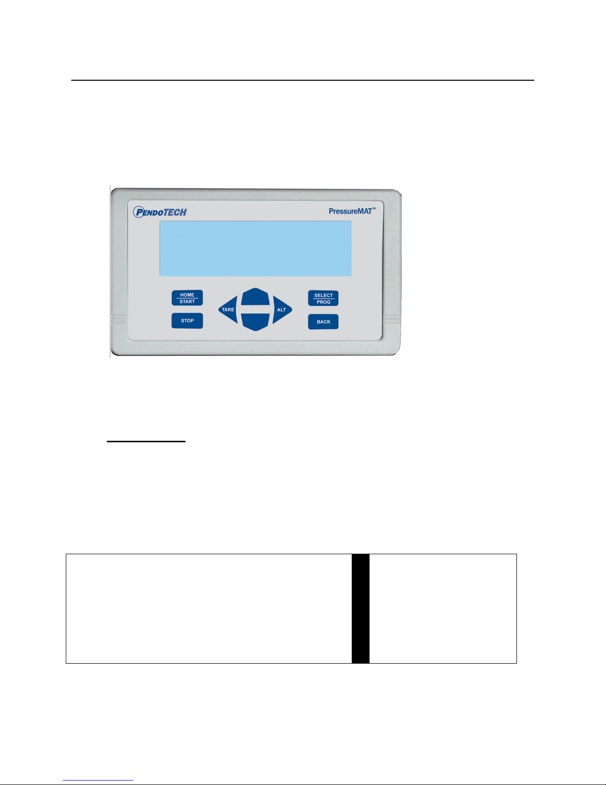
1.2.2. Software Details
The software interface consists of the keypad (shown below) and the 8 line LCD backlit
display. The program/firmware is stored in memory in the control system and cannot be edited
by users. Only settings in the software menus can be changed. The system does not store any
data unless equipped with optional data logger.
There is no power switch so the system cannot be accidentally turned off. When the wall
power supply is connected to the system and plugged into a wall outlet, the welcome screen
will appear momentarily followed by 2 beeps, then the HOME screen will appear.
Home Screen
When the system is powered on, the following HOME screen appears after the welcome screen
with pressures 1 through 4 shown depending on the model number
(with X.XX bar or XX.X psi as designated):
HOME Screen:
Multi-channel unit (PMAT4 shown with all 4 channels): PMAT-S
3 Pressure . . . . . . 0.0 psi
4 Pressure . . . . . . 0.0 psi
Pressure psi
NOTE: Number 3 and 4 Pressure readings are replaced by the flow values and analog input
values in the models PMAT2P, PMAT3P, PMAT3A, PMAT2A, and PMAT2F. Back panel
schematics are shown in Section 3. Different models and/or settings may show different number
of digits to the right of the decimal.
Page 13/48
Page 14

PressureMAT User Guide
HOME/START
Dual Purpose:
2- Used to power on the system if turned off
STOP
Used to reset alarms (if optional alarm latching
turned ON)
TARE/LEFT ARROW
Dual Purpose:
when on the HOME screen
RIGHT ARROW/ALT
Used when in the program menu to scroll the cursor
right
UP ARROW
Three Purposes:
selected value
DOWN ARROW
Three Purposes:
selected value
SELECT/PROG
Used to enter the program menu for the selected
and save changes to a setting
BACK
Dual Purpose:
GLOBAL SETTINGS menu
Revision 8
Keypad
KEY
Function
1- Used to return to the HOME screen from the
program menus
1- Used when in the program menu to scroll
the cursor left
2- Zero pressure sensor of selected channel
1- When on the HOME screen used to select
different input channels
2- In the program menus, used to select
different sub-menus
3- Within a program menu, used to change a
1- When on the HOME screen used to select
different input channels
2- In the program menus, used to select
different sub-menus
3- Within a program menu, used to change a
channel or for the selected menu; used to confirm
1- Used to return to the previous screen when
in a program menu
2- Can be pressed three times to access the
Page 14/48
Page 15

PressureMAT User Guide
Channel X
> Input Viewing
Revision 8
Navigation Between Pressure Sensor Input Channels
At the HOME screen, the UP/DOWN arrows are used to change the selected pressure input
channel.
Zero Calibration for Pressure Sensors
1. Select the desired input channel using the UP/DOWN buttons
2. With a pressure sensor connected to the system and EXPOSED ONLY TO
ATMOSPHERIC PRESSURE, press the Tare Button (LEFT ARROW button) on the
keypad
3. The display should read 0.0 psi / 0.00 bar
4. If 0.0 psi / 0.00 bar is not displayed, press the ZERO/TARE button on the keypad again
Note: a minus sign may appear on the display when it reads 0.0 psi / 0.00 bar; this is
normal as the pressure measured by the system may be a value such as -0.001 but
displayed as -0.0 psi / -0.00 bar.
Alarm Function
If any channel has an alarm set, the alarm function includes:
a. The display screen will blink “ALARM>” on the channel with the alarm
b. An audible tone for 30 seconds during the present alarm (it is reset for a new alarm
condition)
c. If present, a dry contact relay associated with that channel will switch (i.e., if wired as
normally CLOSED, it will OPEN; if wired as normally OPEN, it will CLOSE)
When an alarm condition goes away, all indicators automatically go back to normal (unless the
optional alarm latching function is turned on). If a sensor is inadvertently not connected or
becomes accidentally disconnected during a process the pressure reading will drift and
eventually go to a value greater than 75psi/5.17 bar and an alarm condition will occur if the
high alarm set-point is surpassed or in psi when the value goes above the hard-coded limit of
75. The time until the high alarm occurs may vary and this feature should not be used to
control a process due to the time variance. Associated relays will switch and the analog output
will send greater than 20mA.
Program M enu
To access the program menu for a pressure sensor, press the PROG key on the keypad with the
desired input channel selected. The program menu is mainly used for setting of the high and
low alarm set points and alarm detect delay. After pressing the PROG key, the following
screen appears with X indicating selected channel:
Output Viewing
Input Programming
Output Programming
Note: the PMAT-S menu selections are truncated due to space limitations on certain scre ens
Page 15/48
Page 16

PressureMAT User Guide
Channel X Input Viewing
> * Pressure 0.0 psi
[SELECT] home display value
Channel X Output Viewing
> * Name
SP Typ Monitor
[SELECT] home display value
Select Home Value
Revision 8
At the program menu, the BACK button may be pressed to return to the HOME screen or
SELECT/PROG button pressed with the desired menu selected. The appearance and functions
of the menus are as follows:
Input Viewing
At this screen the UP/DOWN arrows are used to select what value is displayed on the HOME
screen. Press the SELECT/PROG button to select what value appears on the home screen for
the respective channel. The “*” appears next to the current selection for HOME screen
display. In most case this will remain as the Pressure value. PV Signal is the present value of
raw sensor reading. The Service Time is the number of hours the system has been in service.
Pressing the SELECT/PROG button will confirm a change- UNTIL THIS IS DONE, A
SETTING CHANGE IS NOT CONFIRMED. Pressing the HOME or BACK button before
confirming a setting change with the SELECT/PROG button will escape from that program
menu without saving changes made before confirming the entry.
PV Signal x.xxx V
Service Time XXXX hrs
Output Viewing
At this screen the UP/DOWN arrows are used to select what value is displayed on the HOME
screen. Press the SELECT/PROG button to select what value appears on the home screen on
the line under the respective channel. The “*” appears next to the current selection for HOME
screen display. The SP Signal is the milliamp output corresponding to the pressure reading.
Name which by default is blank can be programmed in the in the output programming menu.
Pressing the SELECT/PROG button will confirm a change- UNTIL THIS IS DONE, A
SETTING CHANGE IS NOT CONFIRMED. Pressing the HOME or BACK button before
confirming a setting change with the SELECT/PROG button will escape from that program
menu without saving changes made before confirming the entry.
Multi-channel unit (PMAT4 shown with all 4 channels): PMAT-S
SP Signal 20.000 mA
*>Port Relay <1
SP Sig Relay
Page 16/48
Page 17

PressureMAT User Guide
Channel X Input Programming
> Lo PV Alarm 0.00 bar
Revision 8
Input Programming
At this screen the UP/DOWN arrows are used to select what function to program. Press the
SELECT/PROG button to program the function. The setting or digit of a setting that can be
changed with the UP/DOWN arrows blinks. If there is more than one digit in a setting, use the
RIGHT/LEFT arrows to scroll within the possible digit locations within a setting. Pressing the
SELECT/PROG button will confirm a change- UNTIL THIS IS DONE, A SETTING
CHANGE IS NOT CONFIRMED. Pressing the HOME or BACK button before confirming a
setting change with the SELECT/PROG button will escape from that program menu without
saving changes made before confirming the entry.
Hi PV Alarm 0.00 bar
Alarm Valid 000 sec
Time Alarm 0000 hrs
Comm Port Off
PV Filter Off
Log Type Off
Channel Name
After 30 seconds of inactivity in the program menu, the selected setting to change stops
blinking and the value before the setting was selected is restored.
Changing the Low Pressure Alarm Point- Press the SELECT/PROG with Low Alarm selected
Use the RIGHT ARROW button on the keypad until you get to the digit that you want to
change. Use the DOWN ARROW/UP ARROW buttons on the keypad to change the values.
Press the RIGHT ARROW then UP ARROW to get the minus sign. To change a digit from a
numerical value to zero, change the value to a zero. When the correct value has been selected,
press the SELECT/PROG button and the value will be confirmed. To escape from this menu
without changing the value, press the BACK button and the main channel men u will appear.
Changing the High Pressure Alarm Point- Press the SELECT/PROG with High Alarm selected
Use the RIGHT ARROW button on the keypad until you get to the digit that you want to
change. Use the DOWN ARROW/UP ARROW buttons on the keypad to change the values.
Use the DOWN ARROW/UP ARROW buttons on the keypad to change the values. Press the
RIGHT ARROW then UP ARROW to get the minus sign. To change a digit from a numerical
value to zero, change the value to a zero. When the correct value has been selected, press the
SELECT/PROG button and the value will be confirmed. To escape from this menu without
changing the value, press the BACK button and the main channel menu will appear.
Note: If the High or Low Pressure Alarm Points are set to 0.00 then there will be no
alarm setting and an alarm will only occur if a sensor is disconnected
Page 17/48
Page 18

PressureMAT User Guide
Revision 8
Alarm Valid- This value is set to a default of 0 seconds. This is the amount of time an alarm
condition must be present for an actual alarm to occur. In certain processes with rapidly
changing pressures, this value can be changed to prevent undesired false alarms. Press the
SELECT/PROG with Alarm Valid selected.
Use the RIGHT ARROW button on the keypad until you get to the digit that you want to
change. Use the DOWN ARROW/UP ARROW buttons on the keypad to change the values.
To change a digit from a numerical value to zero, change the value to a zero. When the correct
value has been selected, press the SELECT/PROG button and the value will be confirmed. To
escape from this menu without changing the value, press the BACK button and the main
channel menu will appear.
Comm Port- Indicates data output function. There are several settings but the only active
settings are Off and Serial Report (Sio Report). If Off is selected, no data for the selected
channel is sent out the Serial Port. If Sio Report is selected, data is sent out the Serial RS232
port at the frequency programmed in the Global Settings Menu (contact PendoTECH for more
details on data collection from the PressureMAT). Press the SELECT/PROG with Comm Port
selected. The port settings are:
9600 baud
No Parity
8 data bits
1 stop bit
No flow control
Use the DOWN ARROW/UP ARROW buttons on the keypad to change the settings. When
the correct setting has been selected, press the SELECT/PROG button and the value will be
confirmed. To escape from this menu without changing the value, press the BACK button and
the main channel menu will appear.
The command AZK<cr> can be also used to generate a report as desired. The unit operates
using half duplex request-and-reply protocol; after sending the request, DO NOT send anything
else until the resulting expected response is received. THEN the requestor is free to proceed.
(ie, send one AZK<cr>, THEN make sure a successful response is received).
Note: See Appendix C on Data Collection to a PC
Time Alarm- This value is set to a default of 000 hours. This can be set to trigger an alarm in
a set period of time and most likely will remain at 000 hours which indicates it is not active.
Press the SELECT/PROG with Alarm Valid selected.
Use the RIGHT ARROW button on the keypad until you get to the digit that you want to
change. Use the DOWN ARROW/UP ARROW buttons on the keypad to change the values.
To change a digit from a numerical value to zero, change the value to a zero. When the correct
value has been selected, press the SELECT/PROG button and the value will be confirmed. To
escape from this menu without changing the value, press the BACK button and the main
channel menu will appear.
Page 18/48
Page 19

PressureMAT User Guide
Channel X Output Programming
Port Type Out 0-20mA
Channel X Output Programming
Port Type Out Relay
Revision 8
PV Filter
This option can be used to smooth pressure readings which may be desirable in certain
applications such as a pump pulsating. It is by default turned Off but can be changed to Low,
Medium or High. The feature gives the following smoothing choices:
Low
Medium
High
WARNING: Smoothing will lead to delayed alarm detection because readings are being
averaged and pressure spikes will not be immediately recognized.
Note: See Appendix H for more information and data on this feature.
Name- Only names the menu for the respective input channel.
Output Programming
At this screen the UP/DOWN arrows are used to select what function to program. The only
function active is the Name. The Port Type can be selected and changed but no changes will
be confirmed and will revert to the default setting.
> Chan Name
or
> Chan Name
Press the SELECT/PROG button to program a name that appears on the line under the line
where the pressure value is displayed for the selected channel (if Name is selected on the
Output Viewing menu). A wide range of alpha-numeric digits can be selected. Use the
RIGHT ARROW button on the keypad until you get to the digit that you want to change. Use
the DOWN ARROW/UP ARROW buttons on the keypad to change the values. The “*”
character indicates a space. Pressing the SELECT/PROG button will confirm a changeUNTIL THIS IS DONE, A SETTING CHANGE IS NOT CONFIRMED. Pressing the HOME
or BACK button before confirming a setting change with the SELECT/PROG button will
escape from that program menu without saving changes made before confirming the entry.
Page 19/48
Page 20

PressureMAT User Guide
GLOBAL SETTINGS
> Information
CONTROL SERVICE
> PV Decimal Off
Revision 8
Global Sett ings Menu
The Global Settings menu can be used to program settings for the system that impacts all
channels; turn ON or OFF features, or view system information. To access the Global
Settings menu press the BACK button three times in rapid succession. The following screen
appears:
System Power
Control Service
Communication
Date and Time
Note: Date and Time not present in S model
At this screen the UP/DOWN arrows are used to select the Global Setting. HOME/START
can be pressed at any time to return to the HOME screen.
Information
If SELECT/PROG button pressed, system information including firmware version is displayed.
Press the BACK button to return to the main menu.
System Power
If SELECT/PROG button pressed, the system power is removed. Press the HOME/START to
restore power.
Control Service
If SELECT/PROG button pressed, the following sub-menu appears with the following default
settings:
Pressure Normal
Alarm Latch Off
Backlight High
Audio Beep On
Keypad Secure Off
Note: On model S, Pressure and Backlight not shown
PV Decimal
At this screen the UP/DOWN arrows are used to select the Control Service setting.
If turned on, the 2nd decimal place is shown. If off only one decimal place is shown. In the HR
models, this will enable the 3rd decimal.
Page 20/48
Page 21

PressureMAT User Guide
DATE and TIME
> Date-Time DDMMMYY HH:MM:SS
Revision 8
Pressure
Gives the option to display calculated values on the 4th line of the HOME screen. Options:
Normal: Display pressure reading (PMAT4A or PMAT4R only)
Blank: Display is blank (all models but PMAT2P, 2A, 3A, 2F & 3P)
TMP: Displays (P1+P2)/2 - P3 (all models but PMAT1, 2P, 2A, 3A, 2F & 3P)
deltaP: Displays (P1- P2) (all models but PMAT1, 2P, 2P, 2A, 3A, 2F, & 3P)
Alarm Latch
If turned on, alarm conditions will remain after an alarm state occurred but is no longer present
until the STOP button is pressed.
Backlight
Can be set to High, Medium or Low.
Audio Beep
Can be turned Off.
Keypad Secure
If turned On, the function to zero the sensor with the left arrow is disabled.
Communications
Displays setting not used in the unit at the present time. DO NOT CHANGE SETTINGS.
Date and Time
If SELECT/PROG button pressed, the following sub-menu appears:
Report Next DDMMMYY HH:MM:SS
Report Start DDMMMYY HH:MM:SS
Report Rate 000 hrs
Daylit Time Off
This menu is used mainly for controlling data output to a PC.
Note: See Appendix C on Data Collection to a PC
At this screen the UP/DOWN arrows are used to select the setting.
Page 21/48
Page 22

PressureMAT User Guide
Revision 8
Date-Time
Used to set the current time. Use the RIGHT/LEFT ARROW button on the keypad
until you get to the digit that you want to change. Use the DOWN ARROW/UP
ARROW buttons on the keypad to change the values. To change a digit from a
numerical value to zero, change the value to a zero. When the correct value has been
selected, press the SELECT/PROG button and the value will be confirmed. To escape
from this menu without changing the value, press the BACK button and the main
channel menu will appear.
Next Report
Indicates the next data report time. A report of the current system data is sent out the
serial port with the RS232 protocol and can be captured into a PC program or other
device. The time will be displayed automatically commencing with the start of the first
report, and this field should not be changed by the user. The PressureMAT Data
Acquisition Software does not require reports to be generated automatically but for
other external devices, this is required.
Report Start
Report start is used to set time of the next data report. Use the RIGHT/LEFT ARROW
button on the keypad until you get to the digit that you want to change. Use the
DOWN ARROW/UP ARROW buttons on the keypad to change the values. To change
a digit from a numerical value to zero, change the value to a zero. When the correct
value has been selected, press the SELECT/PROG button and the value will be
confirmed. To escape from this menu without changing the value, press the BACK
button and the main channel menu will appear. The report start time must be set later
than the current time for data output to commence. The The PressureMAT Data
Acquisition Software does not require reports to be generated automatically but for
other external devices, this is required.
Report Rate
Report rate is used to set the frequency of data report. The frequency (sec, min, hours,
days or months may be selected). Use the RIGHT/LEFT ARROW button on the
keypad until you get to the digit that you want to change. Use the DOWN
ARROW/UP ARROW buttons on the keypad to change the values. To change a digit
from a numerical value to zero, change the value to a zero. When the correct value has
been selected, press the SELECT/PROG button and the value will be confirmed. To
escape from this menu without changing the value, press the BACK button and the
main channel menu will appear. The PressureMAT Data Acquisition Software does not
require reports to be generated automatically but for other external devices, this is
required.
Daylight Save
Since the clock is used only to generate data reports that can be time stamped by the
receiving device, it is recommended to keep this in the Off selection.
Page 22/48
Page 23

PressureMAT User Guide
Revision 8
2. Setup and Use of the System
2.1. System Setup*
1. Connect the pressure sensor cables to the back panel. If a pressure sensor is not connected
when power is supplied to the system, the pressure will go to a value greater than 75 psi/
5.17 bar and an high pressure alarm condition will occur on the respective channel(s). If a
sensor is inadvertently disconnected during a process and stops monitoring pressure, there
will be an alarm notification. An associated relay will switch and the analog output will
send >20mA.
2. Connect the analog and relay outputs, if required as shown in Section 1.2.1
3. Connect the pressure sensor(s) to the cable(s) connected to the system.
4. Connect system to appropriate power source.
Note: If a pressure sensor is not connected or is disconnected during operation of the system,
the pressure reading will drift and eventually go to a value greater than 75psi/5.17 bar and
an alarm condition will occur. The time until the high alarm occurs may vary and this
feature should not be used to control a process due to the time variance. Associated relays
will switch and the analog output will send >20mA. Also, a new sensor that has not been
zero-calibrated can bypass an alarm set-point triggering an alarm condition.
5. Using the instructions from the previous section 1.2.2 and while the sensor(s) is at
atmospheric pressure, zero calibrate the sensor(s) being used (if not reading 0.0 psi / 0.00
bar when installed) by pressing the Tare (LEFT ARROW) button with the proper channel
selected.
* See Section 3 for information on the flow meter input function and Section 4 for analog input
function.
Page 23/48
Page 24

PressureMAT User Guide
Revision 8
2.2. Using the System*
1. Using the instructions from the previous section 1.2.3, set the appropriate high and low alarm
pressure settings for each channel. The unit is supplied with the low alarm set at -7 psi (- 0.5
bar) and with the high alarm set at 30 psi (2 bar). These are the set-points that will trigger an
alarm condition. High and low pressure settings are entered on the key pad and if the process
pressure goes below the low setting or above the high setting, the system will go into alarm
state. The alarm function includes:
a. An audible tone for 30 seconds,
If present, a dry contact relay associated with that channel will switch (i.e., if wired as
b.
normally CLOSED, it will OPEN; if wired as normally OPEN, it will CLOSE)
When an alarm condition goes away, all indicators automatically go back to normal (unless the
optional alarm latching function is turned on which requires the STOP button to be pressed to
clear the alarms). If the alarm settings are set to 0.00, then no alarm conditions are monitored,
however, if a sensor is disconnected, an alarm will still occur.
2. If a pressure sensor is not connected or is disconnected during operation of the system, the
pressure reading will drift and eventually go to a value greater than 75psi/5.17 bar and an alarm
condition will occur if the high alarm set-point is surpassed or in psi when the value goes
above the hard-coded limit of 75. . The time until the high alarm occurs may vary and this
feature should not be used to control a process due to the time variance (and a 20mA signal
will be transmitted from the analog output and/or relays will switch, depending on model).
3. The HOME screen will display pressure from the sensors that are connected.
* See Section 3 for information on the flow meter input function and Section 4 for analog input
function.
Page 24/48
Page 25

PressureMAT User Guide
1 Pressure X.XX bar
Revision 8
3. Flow Meter Function in PressureMAT-PLUS (2P, 3P & 2F)
3.1. Display
The home screen displays flow on the 4th line as shown below (PMAT3P shown and bar units shown).
2 Pressure X.XX bar
3 Pressure X.XX bar
4 PV Rate X.XX mL/m
3.2. Back Panel
The back panel of the unit is as shown below:
PMAT3P:
PMAT2P:
Page 25/48
Page 26

PressureMAT User Guide
+5V
( - )Return
Signal: 0-16.38KHz
FLOW
As shown on the back panel label, the SIGNAL
before connecting.
Revision 8
3.3. Connection to Back Panel
External Cable Connections to Back Panel
input is on the middle pin, the return/common is
on the top pin and if required (varies by type of
flow meter) the +5VDC is on the bottom pin.
NOTE: Wire colors may vary- confirm signals
___________________
Common
METER
INPUT
_____________________
3.4. Navigation in the Flow Meter Input Channel
At the HOME screen, the UP/DOWN arrows are used to select the flow input channel. The
flow meter menus are as follows.
Input Viewing
At this screen the UP/DOWN arrows are used to select what value is displayed on the HOME
Panel Connector
screen. Press the SELECT/PROG button to select what value appears on the home screen for
the respective channel. The “*” appears next to the current selection for HOME screen
display. In most case this will remain as the PV Rate value (Present Value Flow Rate).
PV Qty 1 and PV Qty 2 are flow totalizers. They accumulate total flow. They can be reset to
zero by pressing the left arrow button. The PV signal is the frequency of pulses from the flow
meter and this is converted to flow by the pulse constant:
Flow (mL/m) = pulses/sec * 60 sec/min / pulses/mL
The pulse constant is set in the programming menu for the respective channel.
Page 26/48
Page 27

PressureMAT User Guide
Channel 4 Input Viewing
> * PV Qty 1 XXXXX.XX L
[SELECT] home display value
Channel 4 Input Programming
> Port Type In Plse
Channel Name
Revision 8
The Service Time is the number of hours the system has been in service. Pressing the
SELECT/PROG button will confirm a change- UNTIL THIS IS DONE, A SETTING
CHANGE IS NOT CONFIRMED. Pressing the HOME or BACK button before confirming a
setting change with the SELECT/PROG button will escape from that program menu without
saving changes made before confirming the entry.
PV Qty 2 XXXXX.XX L
PV Rate 0.00 L/m
PV Signal 0 Hz
Service Time XXXX hrs
Input Programming
At this screen the UP/DOWN arrows are used to select what function to program. Press the
SELECT/PROG button to program the function. The setting or digit of a setting that can be
changed with the UP/DOWN arrows blinks. If there is more than one digit in a setting, use the
RIGHT/LEFT arrows to scroll within the possible digit locations within a setting. Pressing the
SELECT/PROG button will confirm a change- UNTIL THIS IS DONE, A SETTING
CHANGE IS NOT CONFIRMED. Pressing the HOME or BACK button before confirming a
setting change with the SELECT/PROG button will escape from that program menu without
saving changes made before confirming the entry.
IT IS ONLY RECOMMENDED THAT THE ITEMS IN SHOWN IN BOLD BELOW
ARE CHANGED. SCROLL TO SEE ALL SETTINGS:
Time Base min
Decimal Point xx.x
Measure Units L
Scale Factor 1.000
Pulse Constant 100000 p/L
PV Average 1.0 sec
Lo PV Alarm 0.00 L/min
Hi PV Alarm 0.00 L/min
Alarm Valid 002 sec
Qty1 Alarm 0.00 L
Qty2 Alarm 0.00 L
Time Alarm 0000 hrs
Comm Port Off
Log Type Off
Note: If the Alarm Points are set to 0.00 then there will be no alarm
After 30 seconds of inactivity in the program menu, the selected setting to change stops
blinking and the value before the setting was selected is restored.
Page 27/48
Page 28

PressureMAT User Guide
Revision 8
Changing the Pulse Constant- Press the SELECT/PROG with Pulse Constant selected. The
default value is 100000 pulses/L which is the default value for the PDKT-FM
22WV flow meter with the ¼ inch hosebarb. To determine a pulse constant, set the pulse
constant to 1 and totalize flow through the flow meter rotor. The total flow registered on the
LCD is actually the number of pulses and this can be divided by the volume collected to yield
pulses/mL.
Changing the Alarm Point- Press the SELECT/PROG with the desired Alarm selected. Use
the RIGHT ARROW button on the keypad until you get to the digit that you want to change.
Use the DOWN ARROW/UP ARROW buttons on the keypad to change the values. To
change a digit from a numerical value to zero, change the value to a zero. When the correct
value has been selected, press the SELECT/PROG button and the value will be confirmed. To
escape from this menu without changing the value, press the BACK button and the main
channel menu will appear.
Alarm Valid- This value is set to a default of 0 seconds. This is the amount of time an alarm
condition must be present for an actual alarm to occur. In certain processes with rapidly
changing pressures, this value can be changed to prevent undesired false alarms. Press the
SELECT/PROG with Alarm Valid selected. Use the RIGHT ARROW button on the keypad
until you get to the digit that you want to change. Use the DOWN ARROW/UP ARROW
buttons on the keypad to change the values. To change a digit from a numerical value to zero,
change the value to a zero. When the correct value has been selected, press the
SELECT/PROG button and the value will be confirmed. To escape from this menu without
changing the value, press the BACK button and the main channel menu will appear.
Comm Port- Indicates data output function. There are several settings but the only active
settings are Off and Serial Report (Sio Report). If Off is selected, no data for the selected
channel is sent out the Serial Port. If Sio Report is selected, data is sent out the Serial RS232
port at the frequency programmed in the Global Settings Menu if set for automatic report
generation. Reports are not required to be automatically generated with the PressureMAT Data
Acquisition Software (see Appendix C for details on data collection from the PressureMAT).
Press the SELECT/PROG with Comm Port selected.
Use the DOWN ARROW/UP ARROW buttons on the keypad to change the settings. When
the correct setting has been selected, press the SELECT/PROG button and the value will be
confirmed. To escape from this menu without changing the value, press the BACK button and
the main channel menu will appear.
Note: See User Guide Appendix C on Data Collection to a PC
Page 28/48
Page 29

PressureMAT User Guide
Revision 8
Time Alarm- This value is set to a default of 0000 hours. This can be set to trigger an alarm
in a set period of time and most likely will remain at 0000 hours which indicates it is not
active. Press the SELECT/PROG with Alarm Valid selected.
Use the RIGHT ARROW button on the keypad until you get to the digit that you want to
change. Use the DOWN ARROW/UP ARROW buttons on the keypad to change the values.
To change a digit from a numerical value to zero, change the value to a zero. When the correct
value has been selected, press the SELECT/PROG button and the value will be confirmed. To
escape from this menu without changing the value, press the BACK button and the main
channel menu will appear.
Page 29/48
Page 30

PressureMAT User Guide
1 Pressure X.XX bar
Revision 8
4. Analog Input Function in PressureMAT-PLUS (2P, 3A & 2A only)
4.1. Display
The home screen displays the scaled analog input value as shown below (PMAT2P shown and bar
units shown).
2 Pressure X.XX bar
3 PV X.XX YYY
4 PV Rate X.XX mL/m
4.2. Back Panel
The back panel of the unit is as shown below:
PMAT2P:
Page 30/48
Page 31

PressureMAT User Guide
Channel 3 Input Viewing
> * PV X.XX YYY
[SELECT] home display value
(-) Return
Signal
ANALOG
As shown on the back panel label, the ANALOG
Revision 8
4.3. Connection to Back Panel
External Cable Connections to Back Panel
INPUT signal is on the middle pin and the top pin
is the common / ground. The ANALOG
OUTPUT signal is on the bottom pin and the top
is common ground.
___________________
Panel Connector
Common
INPUT
_____________________
4.4. Navigation in the Analog Input Channel
At the HOME screen, the UP/DOWN arrows are used to select the Analog input channel (3rd
line). The menu is as follows.
Input Viewing
At this screen the UP/DOWN arrows are used to select what value is displayed on the HOME
screen. Press the SELECT/PROG button to select what value appears on the home screen.
The “*” appears next to the current selection for HOME screen display. In most case this will
remain as the PV which is the scaled value based the values entered for the 4-20mA values.
PV Signal is the actual mA input value. The Service Time is the number of hours the system
has been in service. Pressing the SELECT/PROG button will confirm a change- UNTIL THIS
IS DONE, A SETTING CHANGE IS NOT CONFIRMED. Pressing the HOME or BACK
button before confirming a setting change with the SELECT/PROG button will escape from
that program menu without saving changes made before confirming the entry.
PV Signal 0.000 mA
Service Time XXXX hrs
Input Programming
Page 31/48
Page 32

PressureMAT User Guide
Channel 3 Input Programming
> Port Type In 0-20mA
Channel Name
Revision 8
At this screen the UP/DOWN arrows are used to select what function to program. Press the
SELECT/PROG button to program the function. The setting or digit of a setting that can be
changed with the UP/DOWN arrows blinks. If there is more than one digit in a setting, use the
RIGHT/LEFT arrows to scroll within the possible digit locations within a setting. Pressing the
SELECT/PROG button will confirm a change- UNTIL THIS IS DONE, A SETTING
CHANGE IS NOT CONFIRMED. Pressing the HOME or BACK button before confirming a
setting change with the SELECT/PROG button will escape from that program menu without
saving changes made before confirming the entry.
IT IS ONLY RECOMMENDED THAT THE ITEMS IN SHOWN IN BOLD BELOW
ARE CHANGED. SCROLL TO SEE ALL SETTINGS:
Measure Units YYY
Time Base Scalar
Decimal Point xx.x
Low Signal 4.000 mA
Low Units 0.0 YYY
High Signal 20.000 mA
High Units 70.0 YYY
Lo PV Alarm 0.00 YYY
Hi PV Alarm 0.00 YYY
Alarm Valid 000 sec
Time Alarm 0000 hrs
Comm Port Off
Log Type Off
Note: If the Alarm Points are set to 0.00 then there will be no alarms
After 30 seconds of inactivity in the program menu, the selected setting to change stops
blinking and the value before the setting was selected is restored.
Measure Units- This determines the label for the analog input units
Changing the Low and High Units- This determines the scale of the calculated units for the
analog input. The PV is determined by the following formula based on the Low and High
Units entered:
PV = ((PVmA Signal – 4) /16) * (High Units - Low Units) YYY
Changing the Alarm Point- Press the SELECT/PROG with the desired Alarm selected. Use
the RIGHT ARROW button on the keypad until you get to the digit that you want to change.
Use the DOWN ARROW/UP ARROW buttons on the keypad to change the values. To
change a digit from a numerical value to zero, change the value to a zero. When the correct
value has been selected, press the SELECT/PROG button and the value will be confirmed. To
escape from this menu without changing the value, press the BACK button and the main
channel menu will appear.
Page 32/48
Page 33

PressureMAT User Guide
Revision 8
Alarm Valid- This value is set to a default of 0 seconds. This is the amount of time an alarm
condition must be present for an actual alarm to occur. In certain processes with rapidly
changing conditions, this value can be changed to prevent undesired false alarms. Press the
SELECT/PROG with Alarm Valid selected. Use the RIGHT ARROW button on the keypad
until you get to the digit that you want to change. Use the DOWN ARROW/UP ARROW
buttons on the keypad to change the values. To change a digit from a numerical value to zero,
change the value to a zero. When the correct value has been selected, press the
SELECT/PROG button and the value will be confirmed. To escape from this menu without
changing the value, press the BACK button and the main channel menu will appear.
Comm Port- Indicates data output function. There are several settings but the only active
settings are Off and Serial Report (Sio Report). If Off is selected, no data for the selected
channel is sent out the Serial Port. If Sio Report is selected, data is sent out the Serial RS232
port at the frequency programmed in the Global Settings Menu. Reports are not required to be
automatically generated with the PressureMAT Data Acquisition Software (see Appendix C for
details on data collection from the PressureMAT). Press the SELECT/PROG with Comm Port
selected. Use the DOWN ARROW/UP ARROW buttons on the keypad to change the settings.
When the correct setting has been selected, press the SELECT/PROG button and the value will
be confirmed. To escape from this menu without changing the value, press the BACK button
and the main channel menu will appear.
Note: See User Guide Appendix C on Data Collection to a PC
Time Alarm- This value is set to a default of 0000 hours. This can be set to trigger an alarm
in a set period of time and most likely will remain at 0000 hours which indicates it is not
active. Press the SELECT/PROG with Alarm Valid selected.
Use the RIGHT ARROW button on the keypad until you get to the digit that you want to
change. Use the DOWN ARROW/UP ARROW buttons on the keypad to change the values.
To change a digit from a numerical value to zero, change the value to a zero. When the correct
value has been selected, press the SELECT/PROG button and the value will be confirmed. To
escape from this menu without changing the value, press the BACK button and the main
channel menu will appear.
Page 33/48
Page 34

PressureMAT User Guide
Revision 8
5. Cable Information
5.1. Cable for Pressure Inputs
12 feet (3.7 m) in length with a 4 pin connector to connect a pressure sensor on one end
and a male DB 15connector to connect to the PressureMAT on the other end
(DB15 connector connected to PendoTECH Part Number PDKT-650-298)
Wiring:
DB15 Pins: 2: WHITE 7: GREEN 9: RED 12: BLACK and SHEILD (Silver)
Page 34/48
Page 35

PressureMAT User Guide
Revision 8
APPENDIX A: PRODUCT WARRANTY
PENDOTECH LIMITED WARRANTY
LIMITED WARRANTY: Subject to the limitations contained in LIMITATION OF REMEDY AND LIABILITY and except as otherwise expressly
provided herein, PendoTECH LLC (“Seller”) warrants that the Software will execute the programming instructions provided by Seller, and that the
products, systems and goods (“Goods”) manufactured by Seller will be free from defects in materials or workmanship under normal use and
service until the expiration of tw enty -four (24) months from the date of shipment by Seller. Expendable items are warranted to be free from defects
in material and workmanship under normal use and service for a period of ninety (90) days from the date of shipment by Seller. Products
purchased by Seller from a third party for resale to Buyer (“Resale Products”) shall carry only the warranty extended by the original manufacturer.
Buyer agrees that Seller has no liability for Resale Products beyond making a reasonable commercial effort to arrange for procurement and
shipping of the Resale Products. If, within thirty (30) days after Buyer’s discovery of any warranty defects during the applicable warranty period,
Buyer notifies Seller thereof in writing, Seller shall, at its option and as Buyer’s sole and exclusive remedy hereunder, promptly correct any errors
that are found by Seller to exist in the Software, or repair or replace F.O.B. point of manufacture, that portion of the Goods or Software found by
Seller to be defective. All replacements or repairs necessitated by inadequate preventive maintenance, or by normal wear and usage, or by fault
of Buyer, or by unsuitable power sources or by attack or deterioration under unsuitable environmental cond itions, or by abuse, accident , alteration,
misuse, improper installation, modification, repair, storage or handling, or any other cause not the fault of Seller are not covered by this limited
warranty, and shall be at Buyer’s expense. Seller shall not be obligated to pay any costs or charges incurred by Buyer or any other party except
as may be agreed upon in writing in advance by an authorized Seller representative . All costs of dismantlin g, reinstallation and freight and the time
and expenses of Seller’s personnel for site travel and diagnosis under this warranty clause shall be borne by Buyer unless accepted in writing by
Seller. Failure by Buyer to give such written notice of defects within the applicable time period shall be deemed an absolute and unconditional
waiver of Buyer’s claim for such defects. Goods repaired and parts replaced during the warranty period shall be in warranty for the remainder of
the original warranty period or ninety (90) days, whichever is longer. All warranties, either express or implied, extend to BUYER only. All
descriptions, representations and/or other information concerning Goods on the PendoTECH website and/or contained in PendoTECH’s
advertisements, brochures, promotional material, or statements made by employees or sales representatives of PendoTECH are solely for
general informational purposes only and are not binding upon PendoTECH. No employee or sales representative of PendoTECH shall have any
authority to establish, expand or otherwise modify PendoTECH’s warranty associated with the sale of Goods. SELLER shall not be liable to
BUYER in any manner with respect to Goods sold. SELLER MAKES NO REPRESENTATIONS OR WARRANTIES OF ANY TYPE, EXPRESS
OR IMPLIED, AND EXPRESSLY DISCLAIMS AND EXCLUDES ANY REPRESENTATION OR WARRANTY OF MERCHANTABILITY,
FITNESS FOR A PARTICULAR PURPOSE OR USE, NON-INFRINGEMENT OR WARRANTY ARISING FROM USAGE OF TRADE, COURSE
OF DEALING OR PERFORMANCE. PendoTECH, LLC makes no warranty or representation regarding whether or not a customer’s end use of
any PendoTECH product, sys tem or good infringes the valid in tellec tual property rights of others.
LIMITATION OF REMEDY AND LIABILITY: SELLER SHALL N OT B E LI ABL E FOR DAMAGES CAUSED BY DEL AY IN P ERF OR M ANC E.
THE SOLE AND EXCLUSIVE REMEDY FOR BREACH OF WARRANTY HEREUNDER SHALL BE L IMIT ED T O R E PAIR, CO RRE CTION O R
REPLACEMENT UNDER THE LIMITED WARRANTY. IN NO EVENT, REGARDLESS OF THE FORM OF THE CLAIM OR CAUSE OF
ACTION (WHETHER BASED IN CONTRACT, INFRINGEMENT, NEGLIGENCE, STRICT LIABILITY, OTHER TORT OR OTHERWISE), SHALL
SELLER’S LIABILITY TO BUYER AND/OR ITS CUSTOMERS EXCEED THE PRICE TO BUYER OF THE SPECIFIC GOODS
MANUFACTURED BY SELLER GIVING RISE TO THE CLAIM OR CAUSE OF ACTION. BUYER AGREES THAT IN NO EVENT SHALL
SELLER’S LIA BIL IT Y TO BU Y ER A ND /OR IT S CU ST OM ER S EX TEN D TO INC L UD E IN C ID ENT AL , CON SEQ U EN TI AL OR PU N IT IV E
DAMAGES. THE TERM “CONSEQUENTIAL DAMAGES” SHALL INCLUDE, BUT NOT BE LIMITED TO, LOSS OF ANTICIPATED PROFITS,
LOSS OF USE, LOSS OF REVENUE AND COST OF CAPITAL. Rev. 0
Page 35/48
Page 36

PressureMAT User Guide
Revision 8
APPENDIX B: PendoTECH Single Use Pressure Sensors
PendoTECH’s Single Use Pressure Sensors are a low-cost solution for use with tubing and bioprocess
containers and are compatible with both gamma, ETO and autoclave sterilization. They can be
integrated for pressure measurement and control. The sensors are designed for use with products
offered by PendoTECH. Other sensor monitors must be tested for compatibility and PendoTECH
assumes no responsibility of compatibility of performance with other instruments.
Warranty:
They are covered by a separate product warranty from the PressureMAT system.
General Information:
They must be qualified by the user for suitability for an application.
WARNING: EACH PROSPECTIVE USER MUST TEST THE SENSOR FOR ITS
PROPOSED APPLICATION TO DETERMINE ITS SUITABILITY FOR THE PURPOSE
INTENDED PRIOR TO INCORPORATING THE SENSOR TO ANY PROCESS OR
APPLICATION. THE SENSORS ARE NOT INTENDED FOR USE AS COMPONENTS IN
LIFE SUPPORT. THE SENSORS ARE NOT DESIGNED FOR ANY APPLICATION IN
WHICH THE FAILURE OF THE PRODUCT COULD RESULT IN PERSONAL INJURY OR
DEATH.
THEY ARE NOT DESIGNED FOR USE ABOVE 75 PSI (5.2 BAR)
For More Information:
http://www.pendotech.com/pressure
Application Notes are available on Autoclave of the Sensors and Compatibility with NaOH used in
sanitization.
Page 36/48
Page 37

PressureMAT User Guide
Select Model
Pressure Units
Flow Units
Weight Units
View Present Values for current PMAT model and scale if connected
Set Units of Measure from pick-listIndicate if scale connected
Select
PMAT
Model
Display
Calculated
Values
Enter informat ion
that is written to
data file header
Select file
update rate
Start writing
data to file
Tab navigation
Indicates file
location
Scale must be set to:
Continuous data output.
Revision 8
APPENDIX C: PressureMAT Data Acquisition Software
The PendoTECH PressureMAT (PMAT) monitor/transmitter that is used to read the PendoTECH Pressure
Sensors comes with an RS232 data port as a standard feature. PendoTECH has a customized software package
(Part # PMAT-GUI ) to trend data real-time and also collect the data to a file that can be opened by programs
such as Excel. The software has settings to choose the PressureMAT model from a list and it can optionally
perform calculated values such as DeltaP and also trans-membrane pressure that are used for certain filtration
applications. PMAT-PLUS models will collect the flow data into a trend separate from the pressure data. The
PMAT-2PLUS model has an analog input port to which different sensors such as the PendoTECH Temperature
Sensor, UV Sensor, Turbidity Sensor or other sensor can be connected via their 4-20mA transmitter and this
data can be logged with the pressure and flow data. Additionally, a scale with an RS232 output maybe plugged
into the PC directly and the software can acquire weight data along with the PressureMAT data.
Setup View
The setup view is used to enter information specific to the PMAT model and to select calculated values for specific
applications. Data collection from a scale can be activated here also. The units of measure are selected to match the units
on the PressureMAT and scale. At the top, information can be entered that is specific to an experiment and this data is
written to the header of the data file when the data file is created. The data file location is also displayed. The data file
may be updated at a rate of every 2 seconds or slower. All of the inputs to this view are locked out when the “Start Process
Data Collection” button is clicked .
RS232 communication
protocol, with settings:
1200 baud, 7 data bits,
ODD parity, 1 stop bit,
NO HANDSHAKE.
The PMAT model and units are selected by pick-lists. These units are then used for the trends view and used in the column headers
of the data files to indicate the units of the values in each column.
Page 37/48
Page 38

PressureMAT User Guide
Units of
measure
are shown
Axis for
each unit
appears and
can be set to
auto or manual
scaling with
one click
Customize
format of
trend line
Set trend
“FIFO” rate
Ability to
Export data
on the trend
only to a file
Trend view
toolszoom, etc.
Set trend
update rate
Available values
can be selected
for trending
Present
values are
shown
Cursor
Values are
shown
Ability to
enter electronic
notes to the
data file
Cursor value selector
Revision 8
Trends View
The Trends View has the fle xibility to allow customization of the view to meet your requirements. The pick lists allow you
to display the data of interest and at any time items can be added or removed from the plot area. It features auto-scaling
options for all axes or manual scaling by simply typing mix/max values at an axis scale. The cursor tool is useful to
compare older data versus present. Electronic Notes may be entered and the notes will be written to the data file with the
following data record. The trends view features are highlighted below which is shown with a PMAT-2PLUS with
temperature as the analog input and TFF calculations enabled. The plot with legend may also be copied as a picture for
immediate placement into a report or presentation.
Data File
The file may be located in any
directory and is created when the
“Start Process Data Collection”
button is clicked. The data is
written to this file that is locked by
the software until the “End Process
Data Collection” button is clicked .
The file format is CSV that is set to
automatically open with Excel.
A file sample is shown. The notes
column is empty except for where
notes were entered so they are easily
located at the time identified.
Page 38/48
Page 39

PressureMAT User Guide
Revision 8
APPENDIX D: Panel Mount of System
PressureMAT
PMAT (except -S) PMAT-S
All dimensions in inches, +/- 0.015
Page 39/48
Page 40

PressureMAT User Guide
Revision 8
PressureMAT Panel Mount Upgrade Kit- Part # PMAT-PANEL
Comprised of :
- 2 gaskets (one and a spare)
- 4 mounting bracket
- Sensor cables and connector (one for each input)
- Power input connector.
Page 40/48
Page 41

PressureMAT User Guide
Herewith declare that the
Information technology equipment devices for
Product Identification (brand
PressureMAT Monitor, Alarm and Transmitter
PendoTECH Single Use Pres sur e Sensors
Revision 8
APPENDIX E: EC Declaration of Conformity
EC Declaration of Conformity
The undersigned, representing the following supplier:
PendoTECH
174 Nassau Street Suite 256
Princeton, NJ 08542 USA
measurement, monitoring, controlling and
communicating for commercial and light industrial application
models)
are in conformity with the provisions of the following EC Directive(s) when installed in accordance with the
instructions contained in supplied product documentation:
2014/30/EU EMC Directive, Class B, Report A50728I1
2014/35/EU Low Voltage Directive, Report A50728I1
2006/42/EC Machinery Directive, Report R-0709-001
2006/95/EC Low Voltage Directive, Report R-0716-001
and the standards and/or technical specifications for EN 61326-1: 2013 comprised on the following
specifications:
IEC 61000-4-2: 2008, IEC 61000-4-3: 2006+A1 : 2007+A2: 2010, I EC 61000-4/4: 2004+A1: 2010, EN 61000-45:2006, IEC 61000-4-6: 2008, IEC 61000-4-8: 2009, IEC 61000-4-11: 2004, EN 61000-3-2:
2006+A1:2009+A2:2009, EN 61000-3-3: 2008, IEC 61000-3-11: 2000, IEC 61000-3-12: 2011, CISPR 11:
2009+A1: 2010, all inclusive.
Safety requirements for electrical equipment for measurement, control and laboratory use, Part 1: General
Requirements; EN 61010-1:2010.
Safety of Machiner y – Safety-related Parts of Contr ol Systems, Par t 1: General Requir ements; EN/ISO 138 491:2009.
Safety of Machinery – Electrical equipment of machines – Part 12: General Requirements: EN 60204-1:2009.
Year of CE Marking: 2008 through Present
(PMAT1, PMAT1HR, PMAT2, PMAT3, PMAT3P, PMAT4A, PMAT4R,
PMAT2P, PMAT2A, P MAT 2F , PMAT2HR, PMAT3A, PMAT DAQ) with
Supplier:
Signature On file
Name: James Furey
Position: General Manager
Date: April 19, 2016
Page 41/48
Page 42

PressureMAT User Guide
PressureMAT
Position
(AMBER)
Normally
Pinch Valve
No Alarm Signal
OFF
CLOSED
Alarm Signal
ON
OPEN
Device
Component
Specifications
Enclosure
Material: ABS Plastic, top and bottom pieces of box sealed with gasket seal rated
to IP66. Note: Hole w her e the valve is mounted is not water tight.
Pinch
Valves
- BioChem Valve Series 100P (http://www.bio-chemvalve.com/Pinch_Valves.pdf )
- Pinch valve catalog number set for specific size tubing and noted on dev i c e
Relay
Connexal PN 6282-2SG-3XX supplied with mating connector and 12 foot cable
connected to PressureMAT pin “T”.
Power Input
- 24 Volts DC
- 0.5 amp max per valve
WARNING- THE PINCH VALVE WILL CLOSE WHEN THE ALARM SIGNAL IS REMOVED FROM
CAN BYPASS AN ALARM SET-POINT TRIGGERING AN ALARM SIGNAL.
Revision 8
APPENDIX F: Pinch Valve Box Accessory (PDKT-PVE)
Overview
One to four pinch valves can be in each device. The cable to the associated PressureMAT relays must
be wired the normally OPEN configuration (wired to S and T as shown in Section 1.2.1). The valves
are normally closed and when there is NO POWER to the valve box or to the PressureMAT, the valves
will be closed. When power is supplied to the valve box the green LED will illuminate. When there is
an alarm condition on the PressureMAT, the PressureMAT relay will close and the valve will open.
Each valve is in the following configuration relative to the alarm signal on the PressureMAT System.
Condition
LED
Closed
Note: When the power supply is removed from the power inlet connector or the power
supply is unplugged from the wall, the valve will be in the “No Alarm Signal” position
independent of PressureMAT condition.
Signal
Input
with two wire leads for connection to PressureMAT. Connexal pin 1 power (plus,
pin with raised dot) for connection to Pr ess ur e M AT pin “S” ; Connexal pin 2 (minus)
THE VALVE. MAKE SURE NO FINGERS OR OBJECTS EXCEPT TUBING ARE INSERTED
INTO THE PINCH VALVE WHEN THE VALVE CLOSES.
WARNING: IF A PRESSURE SENSOR IS NOT CONNECTED WHEN POWER IS SUPPLIED TO
THE SYSTEM, THE PRESSURE WILL GO TO A VALUE GREATER THAN 77 PSI / 5.3 BAR AND
A HIGH PRESSURE ALARM CONDITION WILL OCCUR ON THE RESPECTIVE CHANNEL(S)
AND THE RELAY WILL SWITCH TO THE ALARM SIGNAL. IF A SENSOR IS INADVERTENTLY
DISCONNECTED DURING A PROCESS AND STOPS MONITORING PRESSURE, THERE WILL
BE AN ALARM SIGNAL. ALSO, A NEW SENSOR THAT HAS NOT BEEN ZERO-CALIBRATED
Page 42/48
Page 43

PressureMAT User Guide
Revision 8
Page 43/48
Page 44

PressureMAT User Guide
Revision 8
APPENDIX G: Using the PressureMAT with WinWedge Software
The PressureMAT has RS232 serial data output to a PC and if the PressureMAT Data Acquistion
Software is not used, WinWedge software may be used to collect data directly to Excel.
Winwedge Standard Edition available at: http://www.taltech.com/products/winwedge.html
Instructions
1. Connect the data output cable to the serial port on the back panel of the PressureMAT
2. Connect to your PC via serial port or to a USB port via adapter cable.
3. In the Global Settings menu, set the clock in the PressureMAT and set next report time after the
current time and set report frequency
4. Open the WinWedge software from the Programs menu
5. Open WinWedge file called PressureMAT4.sw3 (this file is available from PendoTECH)
6. Select port / settings and select the COM port (if not sure of COM port number, Open PC Control
Panel and select System/Hardware/Device Manager/Ports and the COM port number should be
evident)
7. Select File/Save in Winwedge
8. In WinWedge, select Activate/Test mode and pressure data should appear in the table
9. Close the WinWedge window
10. Select Activate Normal Mode but in the future open the PressureMAT4.sw3 file by doubleclicking (this file is available from PendoTECH)
11. Using the Input Programming menu in the PressureMAT, select the Comm Port setting in all
channels of data to be collect to Sio Reports
12. Open the PressureMAT4.xls Excel spreadsheet (this file is available from PendoTECH)
and Enable Macros if asked
13. In cell D1, select the same COM port as selected in WinWedge and data should appear at the freq
set in the PressureMAT. Cell D2 can be used to change the frequency of readings recorded in Excel
coming from the PressureMAT.
14. The Excel spreadsheet can be saved as a different file name so it is suggested that a master copy is
kept and use "Save As" for new projects.
For collection to software besides Excel- The data from each channel is output and the pressure
reading is the 6th field in each row. At the beginning of each report, there is a triangle turned on its
side then a heart. At the end there is a triangle turned on its side then a smiling face:
►♥AZ,00000.01,1, 0.00, 0.00,- 0.1 ,- 0.1 ,00026,X,X,X,X,X,F0
AZ,00000.03,1, 0.00, 0.00, 0.0 , 0.0 ,00010,X,X,X,X,X,11
AZ,00000.05,1, 0.00, 0.00,- 0.0 ,- 0.0 ,00010,X,X,X,X,X,F5
AZ,00000.07,1, 0.00, 0.00,- 0.0 ,- 0.0 ,00010,X,X,X,X,X,F3 ►☻
The command AZK<cr> can be also used to generate a report as desired. The unit operates using half
duplex request-and-reply protocol; after sending the request, DO NOT send anything else until the
resulting expected response is received. THEN the requestor is free to proceed.
(ie, send one AZK<cr>, THEN make sure a successful response is received).
Page 44/48
Page 45

PressureMAT User Guide
Revision 8
APPENDIX H: PressureMAT Smoothing Function (PV Filter)
Filtering of the Present Pressure Value with the PV Filter Function (also referred to as smoothing)
attempts to capture important data trends while leaving out noise and other outliers. In certain
applications, having a filter and an option for filter strength proves advantageous when measuring and
recording pressure with a PendoTECH PressureMAT™. The negative that comes with using a filter is
the increased amount of time it takes to stabilize and reach the actual value (if constant).
WARNING: Smoothing will lead to delayed alarm detection because readings are being
averaged and pressure spikes will not be immediately recognized.
The following set of four graphs gives an example of the how smoothing can present pump pulsation
differently by showing no filtering versus averaging a larger set of data values. The following
statistical analysis is used to demonstrate low, medium and high filtering.
%RSD (relative standard deviation) is a statistical measurement that describes the spread of data with
respect to the mean and the result is expressed as a percentage.
Page 45/48
Page 46

PressureMAT User Guide
Revision 8
Page 46/48
Page 47

PressureMAT User Guide
Revision 8
Page 47/48
Page 48

PressureMAT User Guide
Revision 8
As demonstrated with these four graphs, as more data is averaged as the PV Filter Setting is changed
from Low to Medium to High, the data from the same pumping process appears more stable. The
following graph demonstrates the negative that comes with using a filter- which is the increased
amount of time it takes to stabilize and reach the actual value. In this example, a constant pressure
source was vented in the same manner and the delay to reach zero as more PVs are being average is
apparent:
Page 48/48
 Loading...