

Page 1
Technical Note
Technical Note: PendoTECH Process Control Systems: Pump Calibration
Revision 0
Page 1 of 5
PendoTECH Process Control Systems: Pump
Calibration
1. Introduction
The PendoTECH Filter Screening System (NFF) and TFF Process (TFF) allow users to automatically
control flowrates throughout the duration of an experiment or process. Any pump capable of accepting a
remote-control signal can be interfaced with PendoTECH control systems. PendoTECH systems control
pumps by sending an analog signal which is proportional to the flowrate entered by the user on the
system’s graphical user interface (GUI). The analog output is scaled linearly from the pumps minimum
flowrate to its calculated maximum flowrate. The following note describes the process of configuring a
pump with its nominal flow values and making any necessary adjustments to compensate for the inherent
inefficiencies associated with pump technology.
2. Connecting Pumps
a. PendoTECH NFF System
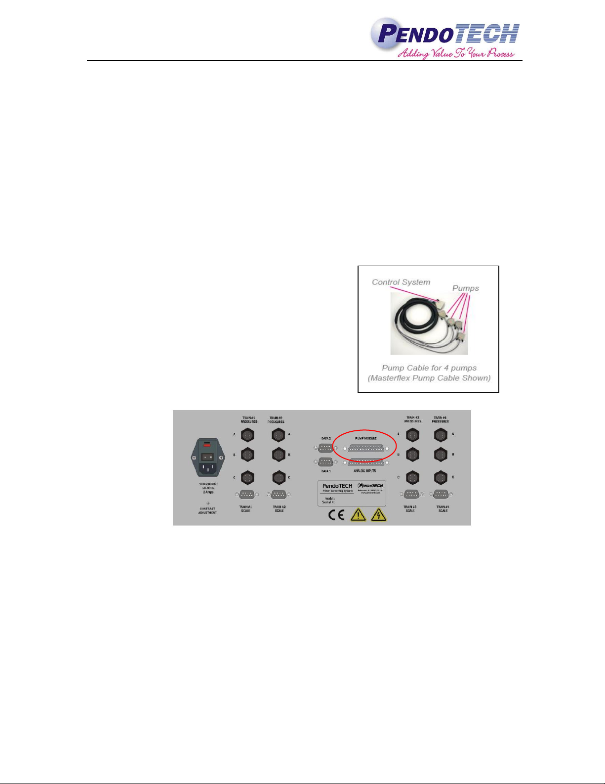
The PendoTECH NFF system is capable of
independently controlling four pumps simultaneously. A
custom cable is included with purchase of the system that
must be specified to match the manufacturer of the pump
to be used with the system, i.e. Masterflex or WatsonMarlow. The four pumps must also be of identical make
and model in order to be used simultaneously. The use of
an adapter cable is available, upon request, if there is a
need to use a pump of different make and model. An
example of a Masterflex pump cable is shown at right and
the pump cable input is called out in the figure below.
Figure 2.1 Back Panel of NFF Control System
b. PendoTECH TFF System
The PendoTECH TFF system can control up to three pumps simultaneously, specifically a main
circulation pump, a diafiltration pump, and a Filtrate/Permeate pump. Unlike the NFF system, the
pumps being used on the TFF system do not need to be of the same make and model. However, it
is important to note that the connection cable between the control system and pump will vary
between different model pumps The pump inputs for the TFF system are called out below.
Note - Only one of the following inputs will be used: Circulation Pump/Circ Pump Alternate
Page 2
Technical Note
Technical Note: PendoTECH Process Control Systems: Pump Calibration
Revision 0
Page 2 of 5
Figure 2.2 Back Panel of TFF Control System
3. Calibrating Pumps
There are two primary parameters that determine the performance of a particular pump; the maximum
rotations per minute (RPM) of the pumps drive and the amount of liquid that is moved per revolution. The
first parameter is labeled in PendoTECH control systems as Max RPM and the second is labeled as
mL/rotation. These parameters must be input on the “Maintenance View” tab of the control system
software each time a new pump is connected to the system. Once the pump calibration parameters are input
they will be saved to the internal memory of the control system. The parameters are also stored within the
PC program and re-sent to the control system each time the PC software is opened. This is done to confirm
the correct settings are stored in the control system.
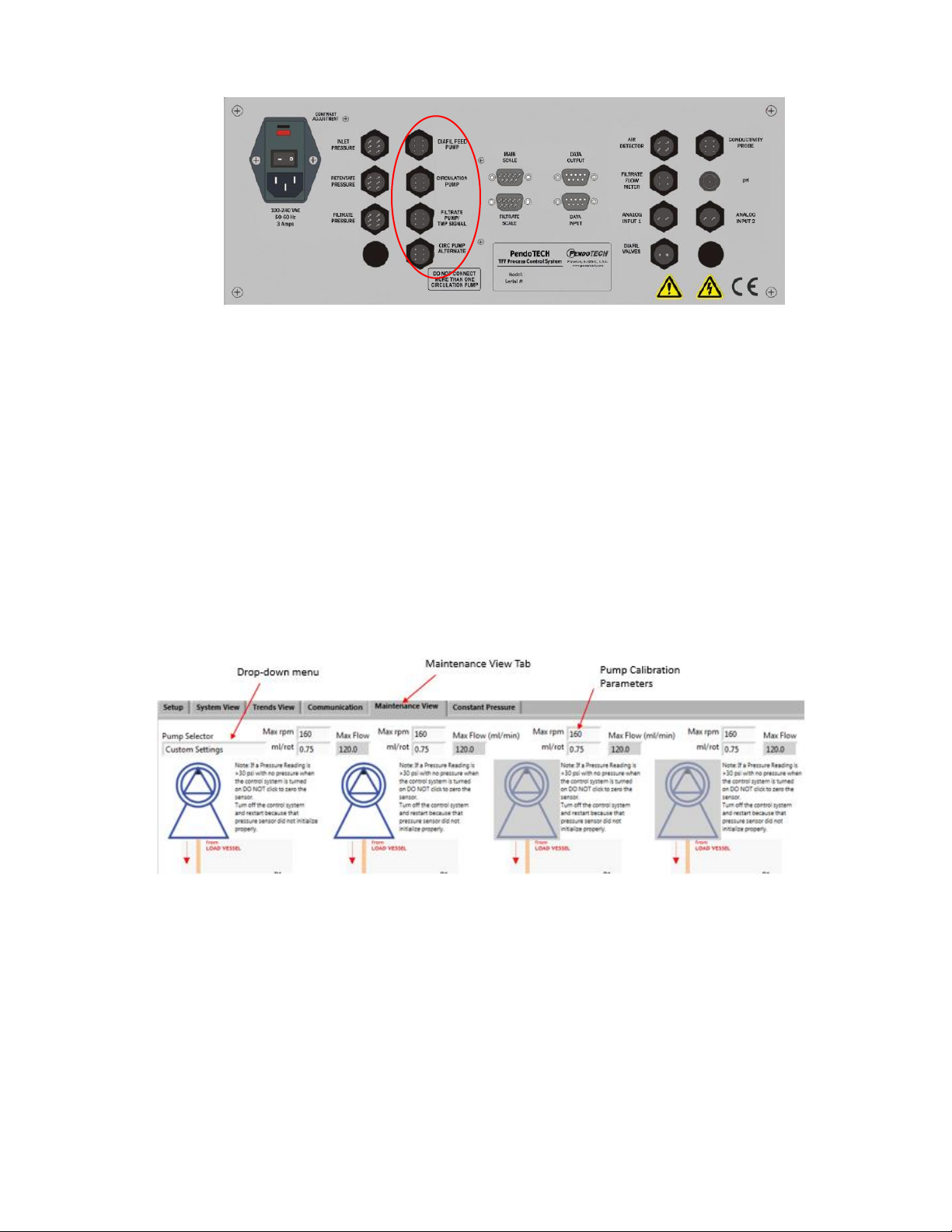
The following screenshot from the NFF control system software shows where the max RPM and mL/rot
values are entered. The control system has a drop-down menu that allows the user to select from a list of
standard pump offerings and will populate the nominal performance values for each pump across all four
trains. The user can also select “Custom Settings” if their pump is not listed or if they want to tweak the
nominal settings for more accurate flow control. Refer to section 4 for the process of verifying the
calibration of each pump.
Figure 3.1 NFF GUI "Maintenance View" Tab
Calibrating pumps on the TFF Process Control System software is done in a similar manner. The
calibration parameters are entered on the “Maintenance View” tab however, there is no drop-down pump
selector. Users normally connect different models of pumps to serve as the circulation pump and
diafiltration feed pump in order to achieve optimal flows. Therefore, each pump calibration must be input
separately into the fields noted below. Selection guides available from PendoTECH for popular peristaltic
pump models that provide this information based on tube size.
Page 3

Technical Note
Technical Note: PendoTECH Process Control Systems: Pump Calibration
Revision 0
Page 3 of 5
Figure 3.2 TFF GUI "Maintenance View" Tab
Note: The input fields for the “Filtrate Pump” will only appear if “Yes” is selected from the dropdown menu located below the text reading “Enable filtrate Pump”.
The following table lists some of the most popular nominal pump calibration paramters for PendoTECH’s
standard offering of pumps used with either the NFF or TFF control system. As shown below, the mL/rot
parameter for peristaltic pumps is dependent on tubing size while it is constant for diaphragm pumps
irregardless of the size of tubing connected to the inlet/outlet. The nominal values listed below are taken
directly from manufacturer documentation.
Manufacturer
Model
Max
RPM
ml/rot
(Size 14)
ml/rot
(Size 16)
ml/rot
(Size 17)
ml/rot
(Size 24)
ml/rot
(Size 36)
Quattroflow
Q150
3000
1
Quattroflow
Q1200
1200
17
Quattroflow
Q4400
583
99
Masterflex
L/S
600
0.22
0.8
2.8
2.8
4.8
Watson-Marlow
120U
200
0.14
0.47
N/A
N/A
N/A
Please refer to vendor documentation provided on PendoTECH.com or contact PendoTECH customer
service if you do not see your pump or tubing size listed above. In most cases, the mL/rot is the maximum
flow in mL/min divided by the maximum RPMs.
4. Flow Verification
This section will illustrate how to further calibrate
pumps if the nominal settings described in section 3
are insufficient. The PendoTECH NFF and TFF
systems control pumps, set to remote control, by
sending analog signals, generally 4-20 mA, that are
proportional to the flowrate entered by the user. The
user enters the unique calibration values for the
pump they are using as described in section 3. The
system then scales the ouput linearly from the
minimum flow value (0 LPM) to the calculated
maximum flowrate which is simply equal to MAX
RPM * mL/rotation. The following graph shows the
control logic for a Masterflex L/S pump with size 16
tubing installed.
Page 4

Technical Note
Technical Note: PendoTECH Process Control Systems: Pump Calibration
Revision 0
Page 4 of 5
Using an output that is scaled linearly assumes an ideal relationship between pump revolution and
displacement at all speeds. This is a fairly safe assumption at lower flowrates, due to limited back pressure
acting on the pump, and will generally yield stable results within 3-5% of the user entered flowrate.
However, with larger systems and higher flowrates, backpressure increases and inefficiences in the
pumping mechanisms are exascerbated leading to a non-linear flowcurve. A more realistic flowcurve is
shown in the graph below. At low-moderate drive speeds the Quattroflow Q150 flowcurve is still largely
linear but as the motor speed and backpressure increase the curve begins to flatten out as the pump is no
longer operating as efficiently.
In order to compensate for the inefficiencies desribed above PendoTECH recommends conducting a flow
verification during a conditioning or flushing step. An off-line bucket check can be performed to determine
the exact flowrate being output by the system. If a retentate flow meter is in line, the permeate can be
closed and the flow meter can be used to monitor pump outptut flow. The following data demonstrates an
extreme case of non-linearity. Data provided by Triangle Process Equipment during testing of Quattroflow
Q4400 with PendoTECH TFF Process Control System.
Shaft Speed RPM
HMI set point (LPM)
Actual (LPM)
Variance
215
21.66
20.7
- 4.5%
297
31
28.2
- 9%
400
40.7
37.88
- 7%
If an error of 5-10% is unacceptable by process standards than a one-point calibration can be performed to
dial in the required flowrate. This can be done by tweaking the ml/rot factor on the maintenace view sceen
as described in section 3. For example, if a 31 LPM flowrate was required, the data above shows that the
system was producing a flowrate that was 9% less than the expected value. To address this, the user could
simply decrease the ml/rot value for the circulation pump by 9% which would lead to the system delivering
exactly the required flowrate. A flowchart can be found in the appendix of this document which details how
to properly execute this procedure.
It is important to note that only the ml/rot value should be changed and not the Max RPM. If necessary this
routine can be performed for each pump operating as part of the system. In the case of the NFF, different
ml/rot values can be entered for each pump by selecting custom settings then tweaking the parameter
accordingly.
This calibration procedure is not unique to PendoTECH control system. For example, the flowrate
displayed on a Masterflex L/S during manual use is simply the pump assuming a linear flowcurve and
using the nominal values listed in section 3. The pump can then be further calibrated by the end user in
order to increase the accuracy of the system The deafult pump calibration procedure is essentially
changing the pump’s nominal mL/rotation parameter. For pumps that have an RPM display only, the user
0
0.5
1
1.5
2
2.5
3
3.5
0 500 1000 1500 2000 2500 3000
Flowrate (L/min)
Pump Speed (RPM)
Quattroflow Q150 Flow Curve
0 Bar
2 Bar
4 Bar
6 Bar
Page 5

Technical Note
Technical Note: PendoTECH Process Control Systems: Pump Calibration
Revision 0
Page 5 of 5
must develop a single or multi-point calibration to define the relationship between RPMs and flow which is
defined by mL/rotation factor.
Please visit PendoTECH.com or contact PendoTECH customer service if any further information is
required.
5. Appendix
Flow veritication Flowchart
 Loading...