

Pella V983492 User Manual

Vinyl Windows and Doors
V983492
Part Number: V983492
© 2010 Pella Corporation
INSTALLATION INSTRUCTION - INSTRUCCIONES DE INSTALACION
350 SERIES O,OX/XO SLIDING PATIO DOOR
WITH FIXED PANEL INSTALLED
Lea las instrucciones en español en el reverso.
Table Of Contents
Installation Instruction Information ...........................................................................................Page-1
Exploded View of Installation and Parts List ............................................................................Page-2
Step 1: Rough Opening Preparation ........................................................................................Page-3
Step 3: Setting and Fastening the Door ..................................................................................Page-4
Step 2: Prepare the Door for Installation .................................................................................Page-4
Step 4: Reinstall the Sliding Panel ............................................................................................Page-7
Step 5: Integrating the Door to the Water Resistive Barrier .................................................Page-8
Step 6: Interior Seal ....................................................................................................................Page-8
Step 7: Sealing the Door to the Exterior Wall Cladding .......................................................Page-9
Step 8: Flush Flange Opening Preparation .......................................................................... Page-11
Step 9: Setting and Fastening the Door in Flush Flange Applications ............................. Page-13
Step 10: Optional Sill Pan Fabrication and Installation ....................................................... Page-15
Cleaning Instructions and Important Notice Preparation ................................................... Page-16
Installation Instructions for Typical Wood Frame Construction and Concrete Block
Constructions.
These instructions were developed and tested for use with typical wood frame wall and concrete
block constructions in a wall system designed to manage water. Installation details specific to
replacement of Aluminum Sliding Doors in Hard Coat Stucco applications can be found at the end
of this instruction. These instructions are not to be used with any other construction method.
Installation instructions for use with other construction methods or multiple units may be obtained
from Pella Corporation or local Pella retailer. Building designs, construction methods, building
materials, and site conditions unique to your project may require an installation method different
from these instructions and additional care. Determining the appropriate installation method is the
responsibility of you, your architect, or construction professional.
The performance of any building is dependent upon the design, installation, and
workmanship of the entire building system. Pella Corporation strongly recommends consulting
an experienced architect, contractor, or structural engineer prior to installation of Pella products.
The individual (building owner, architect, contractor, installer and/or consumer) responsible for the
project must take into account local conditions, building codes, inherent component limitations,
the effects of aging and weathering on building components, and other design issues relevant
to each project. The determination of the suitability of all building components for each project,
as well as the design and installation of flashing and sealing systems, are the responsibility of the
building owner, architect, contractor, installer and/or consumer
Handling and Storage: Provide full support under the framework while storing, moving and
installing the product. DO NOT lift the product by the head member only. Remove the plastic
shipping material prior to storing or installing the product. DO NOT store in direct sunlight. Allow
sufficient spacing between products for ventilation
Page-1

REMEMBER TO USE APPROPRIATE PERSONAL PROTECTIVE EQUIPMENT.
Nailing Fin
Head
Corner
Flashing
Tape
Side
Flashing
Tape
Wood Blocking
Top
Flashing
Tape
Corner
Flashing
Tape
Side Flashing Tape
Sill
Water
Resistive
Barrier
Sheathing
Framing
Sill Flashing Tape #1
Sill Flashing Tape #2
Wood Blocking
Head
Sill
Sill Flashing Tape #1
Sill Flashing Tape #2
Concrete
block
Always read the Vinyl Window and Door Limited Warranty before purchasing
or installing Vinyl Windows and Doors manufactured by Pella Corporation. By
installing this product, you are acknowledging that this Limited Warranty is part of the terms of the
sale. Failure to comply with all Pella installation and maintenance instructions may void your Pella
product warranty. See Limited Warranty for complete details at http://warranty.pella.com.
YOU WILL NEED TO SUPPLY: TOOLS REQUIRED:
• Cedar/impervious shims/spacers (24 to 40)
• 2" galvanized roofing nails (Nail-fin only) (1/4 lb.)
• 1/4" x 2" masonry screws for concrete application
• Closed cell foam backer rod/sealant backer (20 to 30 ft.)
• Pella® SmartFlash™ foil backed butyl window and
door flashing tape or equivalent
• High quality exterior grade polyurethane or
silicone sealant (2 to 3 tubes per door)
SEALANT
SEALANT
• Great Stuff™ Window and Door Insulating Foam Sealant by the
• Dow Chemical Company or equivalent low pressure polyurethane
window and door foam - DO NOT use high pressure or latex foams.
• Pella aluminum sill support or 2 x 4 wood blocking
• Pella sill pan or equivalent
• Interior trim and/or jamb extensions (20 to 30 ft.)
Installation will require two or more
persons for safety reasons.
•Tape measure
•Level
•Square
•Hammer
•Stapler
•Sealant gun
•Scissors or utility knife
•Screwdrivers (#2 Phillips)
•3"-5" Wide putty knife
•Drill
•#2 Phillips bit
•Square (Robertson)
drill bit
Page-2
ROUGH OPENING PREPARATION
1
If replacing an Aluminum sliding door in hardcoat stucco, see Step 8 Flush Flange
Opening Preparation on page 11.
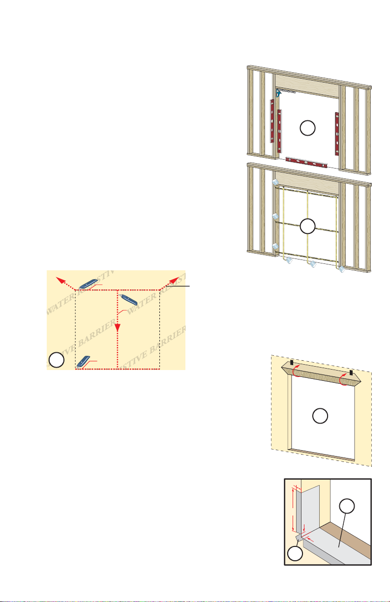
A. Confirm the opening is plumb and level. Ensure
the bottom of the rough opening does not slope
toward the interior.
Note: For peak water performance it is critical the
bottom be level within +/- 1/16".
B. Confirm the door will fit the opening. Measure all
four sides of the opening to make sure it is 1/2" larger
than the door in width and height. Measure the width
at the top, bottom, and center. Measure the height at
the far left side, the far right side, and in the center.
Note: 1-1/2" or more of solid wood blocking is
required around the perimeter of the opening.
Fix any problems with the rough opening
before proceeding.
C. Nail-fin only: Cut the water resistive barrier (1C).
Water Resistive Barrier
1C
1st cut
2nd
cut
3rd cut
4th cut:
Make a 6" cut up from
each top corner at a 45°
angle to allow the water
resistive barrier to be
lapped over the fin at
the head of the door.
Interior
1A
Interior
1B
Exterior
D. Nail-fin Only: Fold the water resistive barrier (1D). Fold
side flaps into the opening and staple to inside wall. Fold
top flap up and temporarily fasten with flashing tape.
E. Apply sill flashing tape #1. Cut a piece of flashing tape 12"
longer than the opening width. Apply at the bottom of the
opening as shown (1E) so it overhangs 1" to the exterior.
Note: The tape is cut 12" longer than the width of the
opening so that it will extend up each side approximately 6".
F. Tab the sill flashing tape and fold. Cut 1" wide tabs at
each corner (1/2" from each side of corner) (1F). Fold tape
to the exterior and press firmly to adhere it to the water
resistive barrier.
Page-3
1D
1"
6"
1/2"
1/2"
1E
1F
ROUGH OPENING PREPARATION (CONTINUED)
1
1"
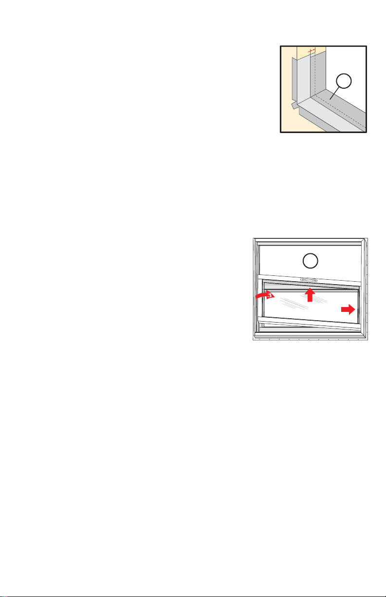
G. Apply sill flashing tape #2. Cut a piece of flashing tape
12" longer than the opening width. Apply at the bottom,
overlapping tape #1 by at least 1". DO NOT allow the tape to
extend past the interior face of the framing (1G).
Note: The flashing tape does not need to extend all the way
to the interior of the framing.
If using optional sill pan, see Step 10 Sill Pan Fabrication and Installation on page 15.
PREPARE THE DOOR FOR INSTALLATION
2
TWO OR MORE PEOPLE WILL BE REQUIRED TO HANDLE THE PANEL SAFELY
A. Remove the packaging from the door. Inspect
the frame and panels for damage. DO NOT install
damaged units.
Note: If screens or hardware are removed from
the door at this time, label them and store them in
a protected area.
B. Locate the kitted parts bag. Remove from unit and
place in a safe location that is accessible during the
door installation.
C. Remove the vent panel. With the jamb side of the
door down, slide the panel all the way to one direction,
while lifting the panel out of the bottom frame pocket.
Swing the panel out of the frame.
D. Transom/Sidelight only: Remove the sill track and
pocket covers by pulling on the paper ring. DO NOT
damage these items as they will be re-installed once
the frame is fastened to the opening.
2B
2
Interior View
1G
1
SETTING AND FASTENING THE DOOR
3
TWO OR MORE PEOPLE WILL BE REQUIRED TO HANDLE THE PANEL SAFELY
If installing in a block replacement or a concrete floor, go to Step 3A to remove the bottom
fin. If NOT removing the bottom fin go to Step B.
A. To remove the bottom fin, lay the door down with the interior facing up. With a utility
knife, carefully score the entire length of the fin three times where it meets the sill. Bend the
fin back and forth a few times, then peel the fin off.
Note: Keep the body of the knife against the frame to prevent gouging the sill.
Page-4
SETTING AND FASTENING THE DOOR (CONTINUED)
3
B. Dry fit the door. Make sure the door is plumb, square
and level. Drill anchor locations with 1/8" masonry bit.
Mark the interior of the door frame at the sill to show a
boundary for sealant placement. Carefully remove and
set the door aside.
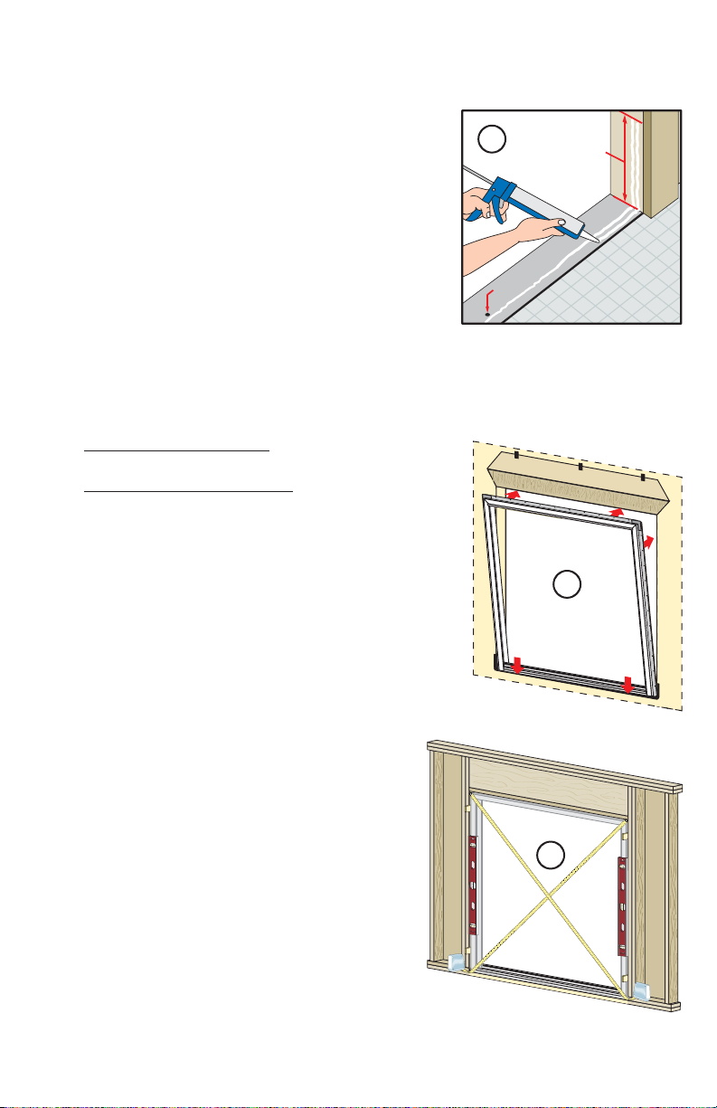
C. Apply two continuous 1/4" to 3/8" diameter beads
of sealant across the sill of the opening and 12" up the
jambs, towards the interior side of the door (between
the anchor holes and interior edge of door). DO
NOT apply sealant between the anchor holes and the
exterior side of the sill plate or floor.
Note: Failure to properly seal the sill attachment
screws and sill plate may allow water to penetrate
the interior of the home.
D. Insert the door from the exterior of the building. Place the bottom of the door at the
bottom of the opening, then tilt the top into position. Center the door between the sides
to allow equal clearance for shimming. Make sure the door is plumb, level and square.
Door Frames with Nail Fin: Insert one 2" galvanized
roofing nail into the top of each jamb nailing fin.
Door Frames without Nail Fin: Insert one screw in the
top hole of each jamb.
Note: When installing doors without a bottom fin, DO
NOT slide the bottom of the door into the opening, as
sliding will damage the sealant lines. Insert sill anchor
screws prior to shimming.
3C
anchor
hole
Interior View
Exterior
3D
12"
E. Plumb and square the door. Insert shims at
the jambs between the door and the sides of
the rough opening. Place shims behind each of
the pre-drilled installation holes. DO NOT place
shims at the sill. DO NOT place shims at the
head until Step 4I.
Page-5
Interior
3E
 Loading...