

Page 1

Owner’s Manual
Pelican WF4/WF8 Premium Whole House
Iron and Manganese Filtration System
Page 2

Pelican WF4/WF8 Premium Whole House Iron and Manganese
Filtration System
Rev R
Page 2
© Copyright 2013 Enviro Water Solutions Inc. All rights reserved.
All information contained herein is the property of Pelican Water Systems. Pelican Water Systems makes
no warranty of any kind with regard to this material, including, but not limited to, the implied warr anties of
merchantability and fitness for a particular purpose. Pelican Water Systems shall not be liable for technical
or editorial errors or omissions contained herein or for incidental or consequential damages in connection
with the furnishing, performance, or use of this material. The information is provided “as is” without
warranty of any kind and is subject to change without notice. This document contains proprietary
information which is protected by copyright. No part of this document may be photocopied, reproduced, or
translated into another language without the prior written consent of Pelican Water Systems. Pelican Water
Systems is an Enviro Water Solutions, Inc. company.
© 2013 Enviro Water Solutions, Inc.
3060 Performance Circle, Suite 2, DeLand, FL 32 72 4
www.pelicanwater.com
(877) 842-1635
Page 3

Pelican WF4/WF8 Premium Whole House Iron and Manganese
Filtration System
Rev R
Page 3
Table of Contents
Table of Contents . . . . . . . . . . . . . . . . . . . . . . . . . . . . . . . . . . . . . . . . . . . . . . . . . . . . . . 3
Product Operation and Specifications . . . . . . . . . . . . . . . . . . . . . . . . . . . . . . . . . . . . . 4
Important Information . . . . . . . . . . . . . . . . . . . . . . . . . . . . . . . . . . . . . . . . . . . . . . . . . 4
Complete Parts List . . . . . . . . . . . . . . . . . . . . . . . . . . . . . . . . . . . . . . . . . . . . . . . . . . . . 5
Installation Overview . . . . . . . . . . . . . . . . . . . . . . . . . . . . . . . . . . . . . . . . . . . . . . . . . . 7
Pre-Installation . . . . . . . . . . . . . . . . . . . . . . . . . . . . . . . . . . . . . . . . . . . . . . . . . . . . . . . 7
Bypass Valve Installation . . . . . . . . . . . . . . . . . . . . . . . . . . . . . . . . . . . . . . . . . . . . . . . . 7
Carbon Tank Soak . . . . . . . . . . . . . . . . . . . . . . . . . . . . . . . . . . . . . . . . . . . . . . . . . . . . 9
Carbon Tank Wash . . . . . . . . . . . . . . . . . . . . . . . . . . . . . . . . . . . . . . . . . . . . . . . . . . . 10
Installation . . . . . . . . . . . . . . . . . . . . . . . . . . . . . . . . . . . . . . . . . . . . . . . . . . . . . . . . . . 11
Pre-Filter Assembly . . . . . . . . . . . . . . . . . . . . . . . . . . . . . . . . . . . . . . . . . . . . . . . . . . . 11
Pre-Filter Installation . . . . . . . . . . . . . . . . . . . . . . . . . . . . . . . . . . . . . . . . . . . . . . . . . 11
Chemical Injector Pump and Solution Tank Installation . . . . . . . . . . . . . . . . . . . . . . . . . 12
Chemical Injector Pump Installation . . . . . . . . . . . . . . . . . . . . . . . . . . . . . . . . . . . . . 12
Solution Tank Installation . . . . . . . . . . . . . . . . . . . . . . . . . . . . . . . . . . . . . . . . . . . . 12
Iron and Manganese Tank Installation . . . . . . . . . . . . . . . . . . . . . . . . . . . . . . . . . . . . . 13
Whole House Water Filter Tank Installation . . . . . . . . . . . . . . . . . . . . . . . . . . . . . . . . . . 14
Complete the Installation . . . . . . . . . . . . . . . . . . . . . . . . . . . . . . . . . . . . . . . . . . . . . . 16
Programming the Electronic Head . . . . . . . . . . . . . . . . . . . . . . . . . . . . . . . . . . . . . . . . 16
Step 1: Setting the Valve . . . . . . . . . . . . . . . . . . . . . . . . . . . . . . . . . . . . . . . . . . . . 16
Step 2: Setting the Time . . . . . . . . . . . . . . . . . . . . . . . . . . . . . . . . . . . . . . . . . . . . . 17
Iron and Manganese Tank Regen . . . . . . . . . . . . . . . . . . . . . . . . . . . . . . . . . . . . . . . . . 17
Testing Chlorine Levels in Water . . . . . . . . . . . . . . . . . . . . . . . . . . . . . . . . . . . . . . . . . 17
Care and Cleaning . . . . . . . . . . . . . . . . . . . . . . . . . . . . . . . . . . . . . . . . . . . . . . . . . . . . 19
Sediment Filter . . . . . . . . . . . . . . . . . . . . . . . . . . . . . . . . . . . . . . . . . . . . . . . . . . . . . 19
Replacing the Sediment Filter . . . . . . . . . . . . . . . . . . . . . . . . . . . . . . . . . . . . . . . . . . . 19
Chemical Injector Pump: . . . . . . . . . . . . . . . . . . . . . . . . . . . . . . . . . . . . . . . . . . . . . . . 19
Solution Tank Refill — Chlorine . . . . . . . . . . . . . . . . . . . . . . . . . . . . . . . . . . . . . . . . . . 19
Troubleshooting . . . . . . . . . . . . . . . . . . . . . . . . . . . . . . . . . . . . . . . . . . . . . . . . . . . . . . 20
Warranty . . . . . . . . . . . . . . . . . . . . . . . . . . . . . . . . . . . . . . . . . . . . . . . . . . . . . . . . . . . 21
Warranty Registration Form . . . . . . . . . . . . . . . . . . . . . . . . . . . . . . . . . . . . . . . . . . . . . 23
Product Certifications . . . . . . . . . . . . . . . . . . . . . . . . . . . . . . . . . . . . . . . . . . . . . . . . . 24
© 2013 Enviro Water Solutions, Inc.
3060 Performance Circle, Suite 2, DeLand, FL 32 72 4
www.pelicanwater.com
(877) 842-1635
Page 4

Pelican WF4/WF8 Premium Whole House Iron and Manganese
CAUTION:
Filtration System
Product Operation and Specifications
Specification Description WF4 WF8
Max Flow Rate* 10 GPM 15 GPM
Minimum Working Pressure 25 PSI
Maximum Working Pressure 80 PSI
Maximum Vacuum 5 inch/127 mm Hg
Operating Temperatures 36°F – 120°F
pH Range 7 - 11
*Minimum Rated Service Flow must be at least 6 GPM.
Important Information
Read these instructions carefully and determine the location of all system components before
beginning installation.
Check all applicable plumbing, building, and electrical codes for installation compliance.
Install the system on the main water supply.
Systems that contain electronic components cannot be installed outside in uncovered areas.
Rev R
Page 4
WARNING:
If this or any other system is installed in a metal (co nductive) plumbing system, i.e. copper or
galvanized metal, the plastic components of the system will interrupt the continuity of the
plumbing system. As a result any errant electricity from improperly grounded appliances
downstream or potential galvanic activity in the plumbing system can no longer ground
through contiguous metal plumbing. Some homes may have been built in accordance with
building codes, which actually encouraged the grounding of electrical appliances through the
plumbing system. Consequently, the installation of a bypass consisting of the same material
as the existing plumbing, or a grounded "jumper wire" bridging the equipment and reestablishing the contiguous conductive nature of the plumbing system must be installed prior
to your systems use.
When adding a filtration/softening system to homes/buildings supplied by well water, the syst em should be
installed following the pressure tank. DO NOT USE this system for pneumatic or hydro pneumatic
applications. If you are using a booster pump, then install this system following the booster
pump. If you have questions, please call customer service.
© 2013 Enviro Water Solutions, Inc.
3060 Performance Circle, Suite 2, DeLand, FL 32 72 4
www.pelicanwater.com
(877) 842-1635
Page 5
Pelican WF4/WF8 Premium Whole House Iron and Manganese
WAX
Filtration System
Rev R
Page 5
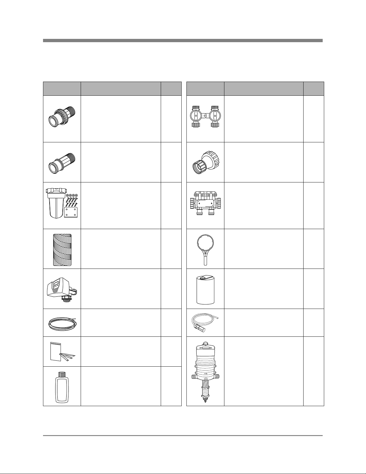
Complete Parts List
Note: Pelican supplies the parts below to accommodate a variety of water supply lines.
Table 1: Parts List
Part Description Qty. Part Description Qty.
1" Plastic Male NPT
Assembly:
V3007-04 WS1 Fitting 1"
1 Bypass Valve:
In/Out Bypass Valve with Red
Arrow Handles
1
Plastic Male NPT Assembly
(2): O-Rings (2), Split Rings
(2), and Connectors (2)
1" PVC Tail Adaptor for
2 Hose Bib Assembly 1
Electronic Head Bypass
Pre-Filter System:
PP5 Big Blue Pre-Filter
1 Bypass Valve for
Electronic Head
1
Housing, Mounting Bracket,
Phillips Head Screws (4), Bolt
Head Screws (4), and Washers
(4)
Sediment Filter:
1 Pre-Filter Wrench 1
PC40-1 5 Micron Poly-Spun
Sediment Filter
Electronic Head 1 Solution Tank 1
PVC Tubing Drain Line
1 Chemical Injector Pump
(50 ft.)
Chlorine Test Strips 1 Chemical Injector Pump 1
Non-Abrasive Auto Wax
1
4 oz. Bottle
© 2013 Enviro Water Solutions, Inc.
3060 Performance Circle, Suite 2, DeLand, FL 32 72 4
1
Tubing
www.pelicanwater.com
(877) 842-1635
Page 6
Pelican WF4/WF8 Premium Whole House Iron and Manganese
Filtration System
Part Description Qty. Part Description Qty.
Rev R
Page 6
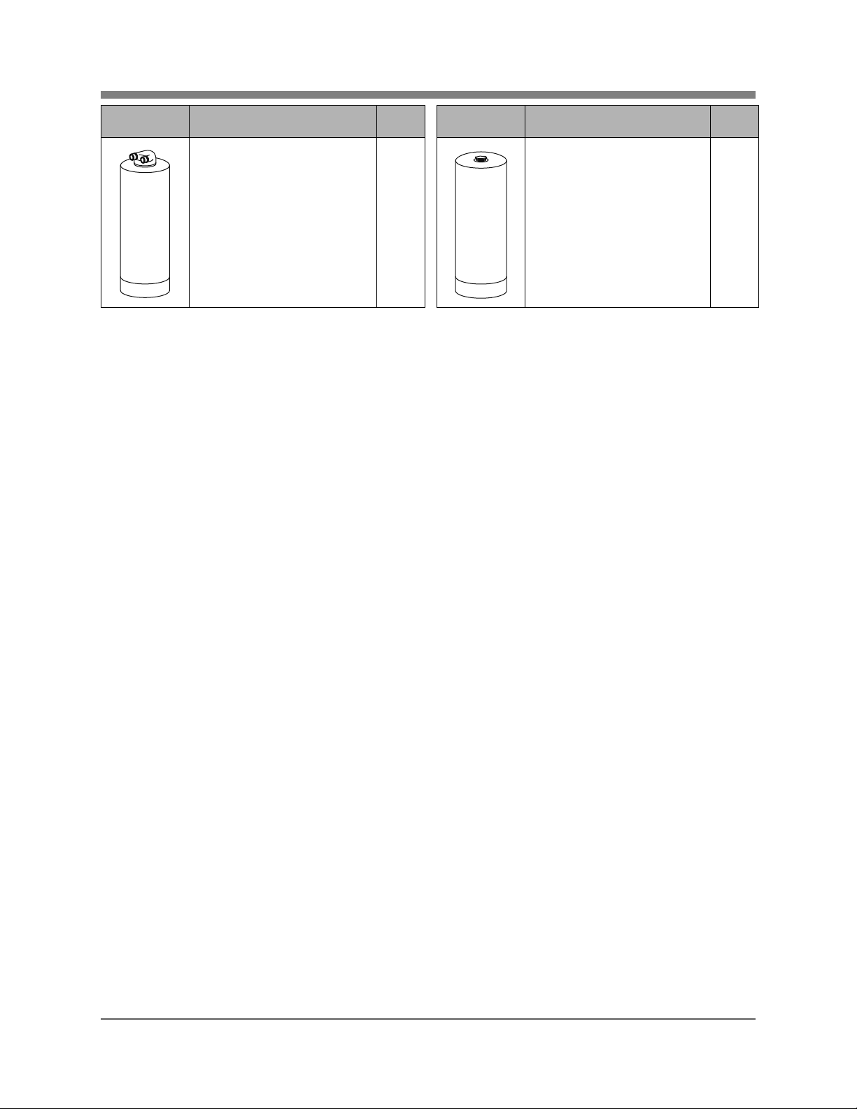
Pelican Whole House
Water Filter
1 Pelican Whole House Iron
Note: Drawings are not to scale.
Additional fittings will be needed to adapt to your plumbing.
1
& Manganese Filter
© 2013 Enviro Water Solutions, Inc.
3060 Performance Circle, Suite 2, DeLand, FL 32 72 4
www.pelicanwater.com
(877) 842-1635
Page 7
Pelican WF4/WF8 Premium Whole House Iron and Manganese
UPFLOW
INLET
DOWNFLOW
INLET
Quick
Connect Nut
Red Arrow
Water Filter
Head
Whole House
Iron & Manganese Filter
Whole House
Water Filter
Electronic
Head
Bypass
Valve
Red
Clip
Front View
Filtration System
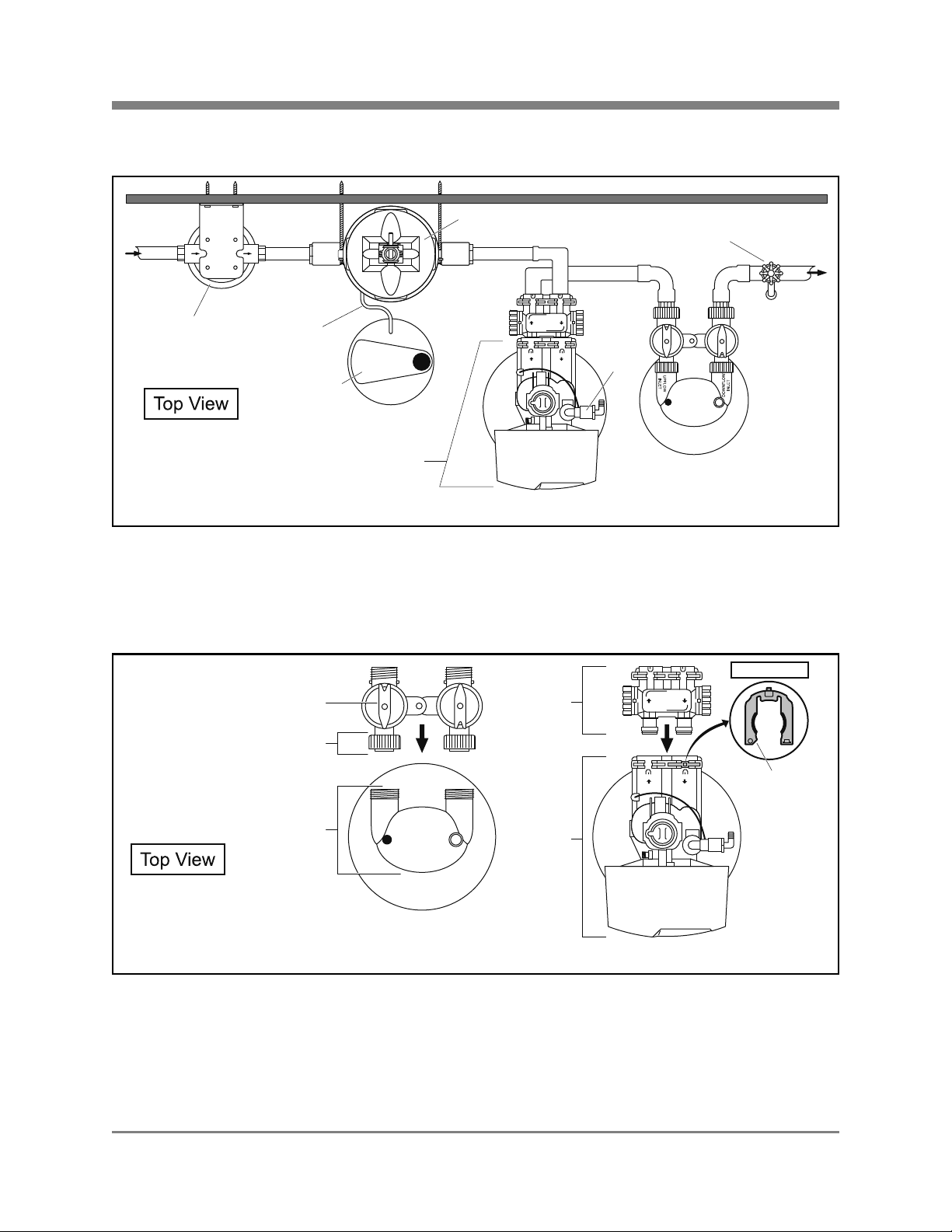
Installation Ov erview
Wall Wall
Rev R
Page 7
IN
Incoming
Water
Supply
Pre-Filter
OUT
Chemical
Injector
Pump Tubing
Solution Tank
Figure 1
Pre-Installation
Bypass Valve Installation
Electronic
Head
Chemical Injector
Pump
Whole House
Iron & Manganese Filter
Spigot
(optional)
Outgoing
Water to
House
Discharge
Line
Whole House
Water Filter
Figure 2
Whole House Water Filter - The Bypass Valve comes pre-assembled and ready to install with the
O-Rings, Split Rings, and Quick Connect Nuts. Push the Bypass Valve into the head of the Pelican Whole
House Water Filter with the unthreaded ends orientated towards the tank and hand-tighten the Quick
Connect Nuts.
© 2013 Enviro Water Solutions, Inc.
3060 Performance Circle, Suite 2, DeLand, FL 32 72 4
www.pelicanwater.com
(877) 842-1635
Page 8

Pelican WF4/WF8 Premium Whole House Iron and Manganese
Notice:
Filtration System
Whole House Iron & Manganese Filter - If the Red Clips are in the slots (female opening of Electronic
Head) remove them. Push the male O-Ring side of the Bypass Valve into the female opening of the
Electronic Head. Push the Red Clips back into the slots to tighten.
The Bypass Valve on the Electr onic Head can be set to Bypass or Service by turning the knobs on the side
of the valve. If the holes are up and down then the tank is in the Bypass Mode. If the holes are side to side
then the tank is in the Service Mode. Do not remove the red clips from the Bypass Valve after connecting
to main water supply.
Note: The Whole House W ater Filter flows in a differ ent direction than the Iron Manganese Filter. The Red
Arrows on the Whole House FilterBypass may be pointing in a diff erent direction then shown in Figure 2. If
this is the case, remove the Red Arrows by pulling them straight up. Turn them around and reposition
correctly onto the Bypass Valve so they are positioned as shown in Figure 2.
Rev R
Page 8
© 2013 Enviro Water Solutions, Inc.
3060 Performance Circle, Suite 2, DeLand, FL 32 72 4
www.pelicanwater.com
(877) 842-1635
Page 9

Pelican WF4/WF8 Premium Whole House Iron and Manganese
!IMPORTANT!
Notice:
Garden
Hose
Hose Bib
Assembly
UPFLOW
INLET
DOWNFLOW
INLET
Water
Bypass Valve
Whole House Water Filter
Filtration System
Rev R
Page 9
Carbon Tank Soak
Your system will not be ready for use for a minimum of 48 hours while the Carbon Soak process takes
place. Please plan your installation accordingly.
Water will flow out of the downflow inlet side of the Bypass Valve during this process. Be sure you perform
this series of steps in a location suitable for water flow.
Figure 3
1. Attach a garden hose to the Hose Bib Assembly
2. Connect the Hose Bib Assembly to the upflow inlet side of the Bypass Valve and hand tighten
3. Fill the Pelican Whole House WaterFilter Tank full until water comes out of downflow inlet side of
the Bypass Valve
4. Turn the water off.
5. Remove the garden hose from the Ho se Bib Assembly. Do not remove the fitting.
6. Allow the carbon tank to soak for at least 48 hours prior to tank installation.
© 2013 Enviro Water Solutions, Inc.
3060 Performance Circle, Suite 2, DeLand, FL 32 72 4
www.pelicanwater.com
(877) 842-1635
Page 10

Pelican WF4/WF8 Premium Whole House Iron and Manganese
!IMPORTANT!
Notice:
UPFLOW
INLET
DOWNFLOW
INLET
Water
Bypass Valve
Whole House Water Filter
Garden
Hose
Hose Bib
Assembly
Filtration System
Rev R
Page 10
Carbon Tank Wash
Do not perform the Carbon Tank Wash until the Carbon Tank Soak process is complete.
Water will flow out of the downflow inlet side of the Bypass Valve during this process. Be sure you perform
this series of steps in a location suitable for water flow.
Figure 4
1. Reattach the garden hose to the Hose Bib Assembly.
2. Slowly turn on the water 1/4 turn for this entire process.
3. Run water through the upflow inlet side of the Bypass Valve for 15-30 minutes or until the water
discharging from the downflow inlet side of the Bypass Valve runs clear.
4. Turn off the water.
5. Remove the Hose Bib Assembly from the upflow inlet side and attach it to the downflow inlet side
of the Bypass Valve.
6. Run the water through the downflow inlet side for 1 minute or until water runs clear.
7. Turn off the water.
8. Remove the Hose Bib Assembly from the Bypass Valve and disconnect the garden hose.
Note: Please save the Hose Bib Assembly as this will be used in the future for the carbon
exchange.
© 2013 Enviro Water Solutions, Inc.
3060 Performance Circle, Suite 2, DeLand, FL 32 72 4
www.pelicanwater.com
(877) 842-1635
Page 11

Pelican WF4/WF8 Premium Whole House Iron and Manganese
Notice:
Pre-Filter Cover
Sediment Filter
O-Ring
Stand Pipe
Blue Pre-Filter Housing
Top View Pre-Filter
Blue Pre-Filter Housing
Inlet Water
Supply
Mounting
Bracket
Filtration System
Installation
Pre-Filter Assembly
Figure 5
1. Unscrew the cover from the Blue Pre-Filter Housing.
2. Remove the plastic covering from the Sediment Filter.
3. Place the Sediment Filter onto the Stand Pipe in the Blue Pre-Filter Housing.
Rev R
Page 11
4. Screw the cover onto the Blue Pre-Filter Housing until hand-tight.
Pre-Filter Installation
Figure 6
1. Shut off the water.
2. Attach the Mounting Bracket to the wall using the supplied Phillips Head Screws and Washers.
3. Attach the Pre-Filter System to the Mounting Bracket using the supplied Bolt Head Screws.
4. Lube the o-ring with clean silicone grease before attaching the cover onto the housing.
5. Tighten the Blue Pre-Filter Housing using the supplied Pre-Filter Wrench (counter clockwise).
6. Determine the size of your inlet water supply line. PVC Reducers may be needed to fit the 1” PreFilter System.
The Pre-Filter Housing comes with a 1” threaded female inlet/outlet and will require additional fittings to
adapt to your plumbing. A shut-off valve is recommended prior to the Pre-Filter System.
© 2013 Enviro Water Solutions, Inc.
3060 Performance Circle, Suite 2, DeLand, FL 32 72 4
www.pelicanwater.com
(877) 842-1635
Page 12

Pelican WF4/WF8 Premium Whole House Iron and Manganese
!IMPORTANT!
!IMPORTANT!
!IMPORTANT!
Incoming
Water
Supply
Outgoing Water
to House
35 Gallon
Solution Tank
Pump Foot
Valve
Chemical Injector
Pump Tubing
Chemical Injector
Pump
Nut
Pre-Filter
Spigot
(optional)
Filtration System
Chemical Injector Pump and Solution Tank Installation
Figure 7
Chemical Injector Pump Installation
Rev R
Page 12
Install the Chemical Injector Pump into the water supply after the Pre-Filter and before any other filtration
or softening system.
1. Determine the size and material of your incoming water supply line from the Pre-Filter System.
2. Mount the Chemical Injector Pump to the wall using the provided brack ets. Line up the inflow and
outflow connections with the current water line.
3. Plumb the Chemical Injector Pump into your water line. The arrow on the body of the Chemical
Injector Pump shows the correct water flow direction. The water should enter and exit the pump
following the direction of the arrow.
Solution Tank Installation
1. Remove the black cap from the opening on the Solution Tank.
2. Drill one 3/8” hole into the top of the Solution Tank.
3. Insert the end of the Chemical Injector Pump Tubing with the pump foot valv e connected, into the
hole which was covered by the black cap on the top of the Solution Tank.
4. Feed and pull the other end of the tubing through the drilled opening on the top of the Solution
Tank.
5. Fill the Solution Tank with 9 cups household bleach and 35 gallons of fresh bottled water. Replace
the cap.
6. Determine the length of Chemical Injector Pump Tubing required to reach the bottom connection
point of the Chemical Injector Pump and then cut the Chemical Injector Pump Tubing to the
appropriate length.
7. Connect the Chemical Injector Pump Tubing to the suction valve on the Chemical Injector Pump.
Ensure the Chemical Injector Pump Tubing is free of kinks.
Ensure Solution Tank is not sitting directly on a concrete floor.
© 2013 Enviro Water Solutions, Inc.
3060 Performance Circle, Suite 2, DeLand, FL 32 72 4
www.pelicanwater.com
(877) 842-1635
Page 13

Pelican WF4/WF8 Premium Whole House Iron and Manganese
Notice:
Notice:
CAUTION:
Discharge
Line
Whole House
Water Filter
Outgoing
Water to
House
Whole House
Iron & Manganese Filter
IN
OUT
Pre-Filter
Incoming
Water
Supply
Wall Wall
Solution Tank
Electronic
Head
Chemical
Injector
Pump Tubing
Chemical Injector
Pump
Spigot
(optional)
Filtration System
Iron and Manganese Tank Installation
Rev R
Page 13
Figure 8
Follow the raised black arrows on the head of the Whole House Iron & Manganese tank.
1. Level the Pelican Whole House Iron & Manganese Filter.
If the tank is not level, lift the tank straight up 6 inches and tap it on the ground until the tank stands
vertical. The bottom of the tank is round and the boot allows the tank to stand upright.
2. Determine the size and material of your incoming w ater supply line fr om the In-Line Injection P ort
and choose the appropriate fittings required to connect it to the Bypass Valve.
Do not over-tighten any of the fittings during installation.
Table 2: Bypass Valve Fittings
Part Description Qty.
Note: The fitting above is designed with a ¼" give to allow f or pr oper pipe alignment. It will not leak and
is intended to have some flexibility.
3. Remove the gray cap from the top of the Whole House Iron & Manganese tank.
1" PVC Tail Adaptor for
Electronic Head Bypass
2
4. Screw the Electronic Head onto the tank hand-tight.
© 2013 Enviro Water Solutions, Inc.
3060 Performance Circle, Suite 2, DeLand, FL 32 72 4
www.pelicanwater.com
(877) 842-1635
Page 14

Pelican WF4/WF8 Premium Whole House Iron and Manganese
Notice:
CAUTION:
Discharge
Line
Whole House
Water Filter
Outgoing
Water to
House
Whole House
Iron & Manganese Filter
IN
OUT
Pre-Filter
Incoming
Water
Supply
Wall Wall
Solution Tank
Electronic
Head
Chemical
Injector
Pump Tubing
Chemical Injector
Pump
Spigot
(optional)
Filtration System
Rev R
Page 14
5. Install the fittings onto the in let and outlet, following the arrows on the Bypass Valve and head.
6. Connect the incoming water supply to the fitting on the inlet side of the Bypass Valve.
7. Connect the outgoing water supply to the outlet side of the Bypass Valve.
8. Firmly press one end of the discharge PVC Tubing Drain Line onto the barbed nose, and secure the
other end of the line to a drain.
Whole House Water Filter Tank Installation
1. Level the Pelican Whole House Wa ter Filter.
If the tank is not level, lift the tank straight up 6 inches and tap it on the ground until the tank stands
vertical. The bottom of the tank is round and the boot allows the tank to stand upright.
Figure 9
2. Determine the size and material of your incoming water supply line from the Whole House Iron &
Manganese Filter and choose the appropriate plumbing required to adapt to the 1” Male NPT
Assembly.
Do not over-tighten any of the fittings during installation.
Table 3: Bypass Valve Fittings
Note: The fitting below is designed with a ¼
is intended to have some flexibility.
Part Description Qty.
© 2013 Enviro Water Solutions, Inc.
3060 Performance Circle, Suite 2, DeLand, FL 32 72 4
1" Plastic Male NPT Assembly:
V3007-04 WS1 Fitting 1" Plastic Ma le NPT
Assembly (2): O-Rings (2), Split Rings
(2), and Connectors (2)
" give to allow for proper pipe alignment. It will not leak and
1
bag
www.pelicanwater.com
(877) 842-1635
Page 15

Pelican WF4/WF8 Premium Whole House Iron and Manganese
Filtration System
3. Install the fitting onto the upflow and downflow inlet sides of the Bypass Valve. Follow the diagram
supplied with the fitting.
4. Connect the incoming water supply from the Pelican Whole House Iron & Manganese Filter to the
fitting on the upflow inlet side of the Bypass Valve.
5. Connect the outgoing water supply to the downflow inlet side of the Bypass Valve.
Rev R
Page 15
© 2013 Enviro Water Solutions, Inc.
3060 Performance Circle, Suite 2, DeLand, FL 32 72 4
www.pelicanwater.com
(877) 842-1635
Page 16

Pelican WF4/WF8 Premium Whole House Iron and Manganese
Extra Cycle
Button
Up
Button
Down
Button
Filtration System
Complete the Installation
1. Turn on the main water supply.
2. Check for leaks.
3. Peel off the protective plastic wrap from the stainless steel tank jackets.
4. Add the Pelican logo sticker in the desired location on the tank.
Rev R
Page 16
5. Wax stainless steel tank jacket(s) with wax provided or any other non-abrasive auto wax a
minimum of 1-2 times per year or as needed based on the installed environment.
Programming the Electronic Head
Note: Power Source - For safety reasons the outlet must be protected by a Ground Fault Circuit
Interrupter (GFCI).
Note: These settings are specific to this system. Do not make changes to the settings unless instructed by
customer service. All settings have to be set by first setting the clock to 12:01 PM. T o r estart programming,
you must start over at step 1. Do not go to a previous step, you must start over at step 1.
Figure 10
Step 1: Setting the Valve
1. Press and hold the UP or DOWN button to change the clock to 12:01 PM.
2. Press the EXTRA CYCLE button once.
3. Press and hold the UP and DOWN buttons together, until DF is displayed in the left corner. Scroll
using the UP and DOWN arrows until "GAL" is selected. Press EXTRA CYCLE.
© 2013 Enviro Water Solutions, Inc.
3060 Performance Circle, Suite 2, DeLand, FL 32 72 4
www.pelicanwater.com
(877) 842-1635
Page 17

Pelican WF4/WF8 Premium Whole House Iron and Manganese
!IMPORTANT!
Filtration System
4. Follow the steps in the table below to finish sett ing the valve. When each setting is displayed, use
the UP and DOWN buttons to scroll to the appropriate data setting displayed in the table. Press
EXTRA CYCLE to select the data setting and go to the next setting.
Table 4: Setting the Valve
Parameter Display (Left Corner) Data Display Set To
VT (Valve Type) Fltr
CT (Control Type) tc
DO (Day Override) 3
RT (Regeneration Time) 2:00
BW (Backwash) 10
RR (Rapid Rinse) 10
Step 2: Setting the Time
1. Press and hold down the UP button to change the clock.
2. Press the EXTRA CYCLE button when the time is set. The water valve displayed will stop flashing
when the time is set.
Rev R
Page 17
Iron and Manganese Tank Regen
You will not be able to use water in the house for approximately 25 minutes during the Regen process.
1. Press and hold the EXTRA CYCLE button for 3 seconds.
Note: Gears will make noise and water will start to flow.
2. Allow the system to EXTRA CYCLE for 25 minutes.
Your manual re gen cycle is complete and the tank is ready for use.
Note: The days between regen may vary based on flow and Iron content. If you are unsure about the
days between regen please contact your Pelican dealer for further help.
Testing Chlorine Levels in Water
1. Put the carbon tank in bypass.
2. Turn on the nearest cold water faucet to the system.
3. Listen and watch the pump to make sure it is pumping. The pump should pulse and not run
continuously. If the water is off, the pump will stop.
4. Let the water run for 10 minutes.
5. After 10 minutes, use the chlorine test strip at the running cold water faucet to check the chlorine
level.
6. The optimum chlorine level reading is 3ppm on the test strip.
a. If the level is lower than 3ppm chlorine, remove the black clip from the ratio adjustment
slide. T urn the ratio adjustment slide 2 full revolutions in the positive direction. Replace the
black clip.
b. If it is higher than 3ppm, remove the black clip from the ratio adjustment slide. Turn the
ratio adjustment slide 2 full revolutions in the negative direction. Replace the black clip.
© 2013 Enviro Water Solutions, Inc.
3060 Performance Circle, Suite 2, DeLand, FL 32 72 4
www.pelicanwater.com
(877) 842-1635
Page 18

Pelican WF4/WF8 Premium Whole House Iron and Manganese
CAUTION:
CAUTION:
Chemical Injector
Pump Tubing
Black Clip
Adjustment Ratio Slide
Filtration System
Rev R
Page 18
Do not remove the silver clip from the ratio adjustment slide when the system is under pressure.
7. Continue with these steps until the system achieves a 3ppm reading on the chlorine test strip.
Figure 11
Avoid high flow rates such as bathtub, utility sinks, hose bibs, multi-headed showers, body sprayers, or
anything that is considered high flow for the first 72 hours to avoid flow restrictions caused by carbon
blockage of the top basket inside the carbon tank.
Carbon dust may be released into the water lines of the house/building during the first few days of water
use after carbon tank installation. The carbon dust is harmless, but may give the water a gray appearance
that should diminish within a week or 10 days depending on water use.
© 2013 Enviro Water Solutions, Inc.
3060 Performance Circle, Suite 2, DeLand, FL 32 72 4
www.pelicanwater.com
(877) 842-1635
Page 19

Pelican WF4/WF8 Premium Whole House Iron and Manganese
Pre-Filter Cover
Sediment Filter
O-Ring
Stand Pipe
Blue Pre-Filter Housing
Filtration System
Rev R
Page 19
Care and Cleaning
Sediment Filter
It is recommended that the Sediment Filter be replaced every 6-9 months depending on the amount of
sediment present in the water supply. If the system has been working properly and the pressure is
slowing, it may be time to change the Sediment Filter. Check the Sediment Filter and replace if necessary.
Replacing the Sediment Filter
1. Turn off the main water supply to the Pre-Filter System and bypass all tanks.
2. Run a faucet (cold water) inside the house to relieve the pressure.
3. Unscrew the Blue Pre-Filter Housing clockwise using the supplied Pre-Filter Wrench.
4. Remove the existing Sediment Filter and discard.
5. Remove the O-Ring and wipe the groove and O-Ring clean. Lubricate the O-Ring with a coating of
clean silicone grease. Replace O-Ring and press the O-Ring down into the groove with two fingers.
Note: This step is important to ensure the proper filter seal. Make sure the O-Ring is seated level
in the groove. If the O-Ring appears damaged, stretched, or crimped it should be replaced at this
time.
6. Place a new Sediment Filter onto the Stand Pipe in the Blue Pre-Filter Housing.
7. Screw the Blue Pre-Filter Housing onto the Pre-Filter Cover.
8. Turn on main water supply slowly to allow the Pre-Filter System to fill with water and put tanks
back in service, out of bypass.
9. Check for leaks.
Chemical Injector Pump:
1. Change every six months (Kit A - part number P-SDP-A) - 2 o-rings and dosage piston. One extra
Kit A is included with your original purchase.
2. Change every year (Kit C- part number P-SDP-C) - 2 o-rings, dosage piston, and shaft.
Note: Spare kits for replacement purposes can be obtained by calling your customer service
representative at Pelican Water.
Solution Tank Refill — Chlorine
1. Check the level of the Solution Tank once per month. Do not let the liquid in the tank fall below
¼full.
2. Fill the tank with 9 cups of household bleach and 35 gallons of treated water (water that has gone
through your filtration system). Replace the cap.
© 2013 Enviro Water Solutions, Inc.
3060 Performance Circle, Suite 2, DeLand, FL 32 72 4
www.pelicanwater.com
(877) 842-1635
Page 20

Pelican WF4/WF8 Premium Whole House Iron and Manganese
Unlevel
Tank
Boot
Unlevel
Tank
Boot
Level
Ta nk
Unlevel
Boot
Filtration System
Rev R
Page 20
Troubleshooting
Problem Solution
Water leaking at the top of the tank around the head. You may need to turn the head to tighten it. The tank
head is pre-installed hand-tight, do not overtighten the
head (just turn it snug).
The tank leans to one side or is not level. If the tank is not level, lift the tank straight up 6 inches
and tap it on the ground until the tank stands vertical.
The bottom of the tank is round and the boot allows the
tank to stand upright.
Water pressure is slowing. It is recommended that the Sediment Filter be replaced
every 6-9 months depending on the amount of
sediment present in the water supply. If the system has
been working properly and the pressure is slowing, it
may be time to change the Sediment Filter. Check the
Sediment Filter and replace if necessary.
Iron appears in the water. Adjust settings on Chemical Injector Pump by removing
black clip on the adjustment ratio slide and turning the
adjustment ratio slide 2 full revolutions in the positive
direction. See graphic on page 18 to locate adjustment
ratio slide. If problem persists, increase backwash
frequency by one day.
Water appears grey or cloudy. Water may appear grey or cloudy for the first seven to
ten days after installation due to extra carbon dust.
Water pressure is slowing immediately after installation. High flow rates such as bathtubs, utility sinks, hose
bibs, multi-headed showers, body sprayers, or anything
that is considered high flow for the first 72 hours should
be avoided. If you suspect a carbon blockage of the top
basket due to a high-flow situation within the first 72
hours of installation, turn off any running water for at
least 10 minutes. This will clear the blockage and you
can resume using water at low or normal flow rates.
© 2013 Enviro Water Solutions, Inc.
3060 Performance Circle, Suite 2, DeLand, FL 32 72 4
www.pelicanwater.com
(877) 842-1635
Page 21

Pelican WF4/WF8 Premium Whole House Iron and Manganese
Filtration System
Rev R
Page 21
Warranty
Pelicans Limited Lifetime Warranty
Pelican Water ("Pelican") warrants to the end user ("customer") that its tanks (13" & smaller), valves, in/
out heads, bypass's, fittings, Natursoft media and housings ("Covered Items") will be free from defects in
material and workmanship under normal use and service for the life of the system. No warranty is made
with respect to defects or damaged due to neglect, misuse, alterations, accident, misapplication, physical
damage, installation on water quality outside guidelines for system or damaged caused by fire, acts of
God, or freezing.**
Pelican Superdos Professional Chemical Injector Pump Warranty
Pelican Water ("Pelican") warrants to the end user ("customer") that its Superdos Professional Chemical
Injector Pump Motor (upper half of unit) will be free from defects in material and workmanship under
normal use and service for a period of 1 year. The Superdos Professional Chemical Injector Pump
Adjustment Ratio Side (lower half of unit) will be free from defects in material and workmanship under
normal use and service for a period of 90 days. The Chemical Injector Pump tubing is not covered as part
of this warranty.
Limitations and Responsibilities
Pelican's obligation to the customer under these warranties shall be limited, at its option, to replacement
or repair of Covered Items by these warranties, labor is not covered. Prior to return or repair of Covered
Items, the customer must obtain a return goods authorization number fr om Pelican and at P elicans option,
return the Covered Items freight prepaid. Any Covered Item repaired or replaced under these warranties
will be returned prepaid standard freight to the original point of shipment. Expedited freight options are
available at customer expense.
No warranty is made with respect to defects or damaged due to neglect, misuse, alterations, accident,
misapplication, physical damage, or damaged caused by fire, acts of God, or freezing. These warranties
apply only to the original registered owner so long as the owner owns the home in which the unit was
originally installed. Customer must register their system with Pelican within 90 days of purchase* in order
to obtain a warranty. Warranty will discontinue after the unit is removed from the location where it was
originally installed. Warranty begins on the date of delivery of product to the customer. Improper
maintenance of system (i.e. not replacing filters or media) on time will be considered "neglect".
Installation of any system on water conditions outside of or beyond the recommended specs of any system
voids any wa r ra nty.
Pelican gives this warranty to the customer in lieu of all other warranties, express or implied, including
without limitation any implied warranties of merchantability or fitness for a particular purpose or treatment
of certain water and hereby expressly disclaims all other such warranties. Pelican's liability her eunder shall
not exceed the cost of the product. Under no circumstances will Pelican be liable for any incidental or
consequential damages or for any other loss, damage or expense of any kind, including loss of use, arising
in connection with the installation or use or inability to use the Covered Items or any water treatment
system the Covered Items are incorporated into. These warranties are go verned by the laws of the state of
Florida and may change at any time without notice.
*Failure by California and Quebec residents to complete the product registration form does not diminish
their warranty rights.
**For all orders placed on or after June 3rd, 2011.
Manufacturer’s Performance Guarantee
The Pelican PC600 Premium Whole House W ater Filter is guar anteed to perform f or 600,000 gallons or (5)
years whichever comes first. The Pelican PC1000 Premium Whole House Water Filter is guaranteed to
perform for 1,000,000 gallons or (5) years whichever comes first. The authorized dealers shall be
© 2013 Enviro Water Solutions, Inc.
3060 Performance Circle, Suite 2, DeLand, FL 32 72 4
www.pelicanwater.com
(877) 842-1635
Page 22

Pelican WF4/WF8 Premium Whole House Iron and Manganese
Filtration System
responsible for the repair or replacement of defective media only, labor to replace the media is the
responsibility of the purchaser.
Rev R
Page 22
© 2013 Enviro Water Solutions, Inc.
3060 Performance Circle, Suite 2, DeLand, FL 32 72 4
www.pelicanwater.com
(877) 842-1635
Page 23

Pelican WF4/WF8 Premium Whole House Iron and Manganese
Date Item(s) were Received: Order ID#: Model:
Dealer Purchased From:
Name:
Address:
City: State: Zip:
Model/Serial Number:
Filtration System
Warranty Registration Form
Send in this Warranty Registration Form to validate your warranty or visit
www.PelicanWater.com
Pelican Warranty Registration Form
to complete warranty registration form online.
Rev R
Page 23
Send To:
Pelican Water Sys tems
3060 Performance Circle, Suite 2
DeLand, FL 32724
Phone: 1-(877) 842-1635
Plumber’s Information (optional)
We like to recommend good plumbers thr oughout the USA and if you were happy with your inst aller please
give us their information so we can pass it on as a courtesy. Thank you for your time.
Name of Plumbing Company used to install system: _____________________________________
Phone #: (_____)-__________________ of the Plumbing installer
© 2013 Enviro Water Solutions, Inc.
3060 Performance Circle, Suite 2, DeLand, FL 32 72 4
www.pelicanwater.com
(877) 842-1635
Page 24

Pelican WF4/WF8 Premium Whole House Iron and Manganese
!IMPORTANT!
Filtration System
Do not use where water is microbiologically unsafe or with water of unknown quality without proper
disinfection before or after the filter/softener system.
Page 24
Product Certifications
Pelican NaturSoft-NS3/NS6 – WQA Gold Seal tested and certified under NSF/
ANSI61 for material safety and tested according to NSF/ANSI 42 for structural integrity
only
Clack V3007-xx Bypass Fittings – WWQA Gold Seal Certified to NSF/ANSI Standard
44 for material safety and structural integrity only
U.S. Green Building Council
Rev R
© 2013 Enviro Water Solutions, Inc.
3060 Performance Circle, Suite 2, DeLand, FL 32 72 4
www.pelicanwater.com
(877) 842-1635
 Loading...