

Pelican WF10 User Manual
Owner’s Manual
Pelican Water Systems
Pelican WF6/WF10 Iron/Manganese
Filter & Salt Free Softener
WF6/WF10 Rev K —
Pelican Water Systems
Pelican WF6/WF10 Iron/Manganese Filter and Salt Free Softener
Page 2
© Copyright 2011 Enviro Water Solutions Inc. All rights reserved.
All information contained herein is the property of Pelican Water Systems. Pelican Water Systems makes
no warranty of any kind with regard to this material, including, but not limited to, the implied warranties of
merchantability and fitness for a particular purpose. Pelican Water Systems shall not be liable for technical
or editorial errors or omissions contained herein or for incidental or consequential damages in connection
with the furnishing, performance, or use of this material. The information is provided “as is” without
warranty of any kind and is subject to change without notice. This document contains proprietary
information which is protected by copyright. No part of this document may be photocopied, reproduced, or
translated into another language without the prior written consent of Pelican Water Systems. Pelican Water
Systems is an Enviro Water Solutions, Inc. company.
© 2011 Enviro Water Solutions, Inc.
3060 Performance Circle, Suite 2, DeLand, FL 32 72 4
www.pelicanwater.com
(877) 842-1635

WF6/WF10 Rev K —
Pelican Water Systems
Pelican WF6/WF10 Iron/Manganese Filter and Salt Free Softener
Page 3
Table of Contents
Table of Contents . . . . . . . . . . . . . . . . . . . . . . . . . . . . . . . . . . . . . . . . . . . . . . . . . . . . . . 3
Product Operation and Specifications . . . . . . . . . . . . . . . . . . . . . . . . . . . . . . . . . . . . . 4
Important Information . . . . . . . . . . . . . . . . . . . . . . . . . . . . . . . . . . . . . . . . . . . . . . . . . 4
Water Conditions for Operation . . . . . . . . . . . . . . . . . . . . . . . . . . . . . . . . . . . . . . . . . . . 4
Complete Parts List . . . . . . . . . . . . . . . . . . . . . . . . . . . . . . . . . . . . . . . . . . . . . . . . . . . . 5
Installation Overview . . . . . . . . . . . . . . . . . . . . . . . . . . . . . . . . . . . . . . . . . . . . . . . . . . 7
Pre-Installation . . . . . . . . . . . . . . . . . . . . . . . . . . . . . . . . . . . . . . . . . . . . . . . . . . . . . . . 7
Bypass Valve Installation . . . . . . . . . . . . . . . . . . . . . . . . . . . . . . . . . . . . . . . . . . . . . . . . 7
Carbon Tank Soak . . . . . . . . . . . . . . . . . . . . . . . . . . . . . . . . . . . . . . . . . . . . . . . . . . . . 9
Carbon Tank Wash . . . . . . . . . . . . . . . . . . . . . . . . . . . . . . . . . . . . . . . . . . . . . . . . . . . 10
Installation . . . . . . . . . . . . . . . . . . . . . . . . . . . . . . . . . . . . . . . . . . . . . . . . . . . . . . . . . . 11
Pre-Filter Assembly . . . . . . . . . . . . . . . . . . . . . . . . . . . . . . . . . . . . . . . . . . . . . . . . . . . 11
Pre-Filter Installation . . . . . . . . . . . . . . . . . . . . . . . . . . . . . . . . . . . . . . . . . . . . . . . . . 11
Chemical Injector Pump and Solution Tank Installation . . . . . . . . . . . . . . . . . . . . . . . . . 12
Chemical Injector Pump Installation . . . . . . . . . . . . . . . . . . . . . . . . . . . . . . . . . . . . . 12
Solution Tank Installation . . . . . . . . . . . . . . . . . . . . . . . . . . . . . . . . . . . . . . . . . . . . 12
Iron and Manganese Tank Installation . . . . . . . . . . . . . . . . . . . . . . . . . . . . . . . . . . . . . 13
Whole House Water Filter Tank Installation . . . . . . . . . . . . . . . . . . . . . . . . . . . . . . . . . . 14
Whole House Salt Free Water Softener/Conditioner Tank Installation . . . . . . . . . . . . . . . . 16
Media Soak . . . . . . . . . . . . . . . . . . . . . . . . . . . . . . . . . . . . . . . . . . . . . . . . . . . . . . . . 17
Media Flush/Condition . . . . . . . . . . . . . . . . . . . . . . . . . . . . . . . . . . . . . . . . . . . . . . . . 17
Complete the Installation . . . . . . . . . . . . . . . . . . . . . . . . . . . . . . . . . . . . . . . . . . . . . . 18
Programming the Electronic Head . . . . . . . . . . . . . . . . . . . . . . . . . . . . . . . . . . . . . . . . 18
Step 1: Setting the Valve . . . . . . . . . . . . . . . . . . . . . . . . . . . . . . . . . . . . . . . . . . . . 18
Step 2: Set Time . . . . . . . . . . . . . . . . . . . . . . . . . . . . . . . . . . . . . . . . . . . . . . . . . . 18
Iron and Manganese Tank Regen . . . . . . . . . . . . . . . . . . . . . . . . . . . . . . . . . . . . . . . . . 19
Testing Chlorine Levels in Water . . . . . . . . . . . . . . . . . . . . . . . . . . . . . . . . . . . . . . . . . 19
Clean your Hot Water Heater (optional) . . . . . . . . . . . . . . . . . . . . . . . . . . . . . . . . . . . . 20
What to Expect with your New Salt Free Water Softener/Conditioner . . . . . . . . . . . . . . . 21
Adding the Pelican Logo Sticker: . . . . . . . . . . . . . . . . . . . . . . . . . . . . . . . . . . . . . . . . . 22
Care and Cleaning . . . . . . . . . . . . . . . . . . . . . . . . . . . . . . . . . . . . . . . . . . . . . . . . . . . . 23
Sediment Filter . . . . . . . . . . . . . . . . . . . . . . . . . . . . . . . . . . . . . . . . . . . . . . . . . . . . . 23
Replacing the Sediment Filter . . . . . . . . . . . . . . . . . . . . . . . . . . . . . . . . . . . . . . . . . . . 23
Chemical Injector Pump: . . . . . . . . . . . . . . . . . . . . . . . . . . . . . . . . . . . . . . . . . . . . . . . 23
Solution Tank Refill — Chlorine . . . . . . . . . . . . . . . . . . . . . . . . . . . . . . . . . . . . . . . . . . 24
Troubleshooting . . . . . . . . . . . . . . . . . . . . . . . . . . . . . . . . . . . . . . . . . . . . . . . . . . . . . . 25
Warranty . . . . . . . . . . . . . . . . . . . . . . . . . . . . . . . . . . . . . . . . . . . . . . . . . . . . . . . . . . . 26
Warranty Registration Form . . . . . . . . . . . . . . . . . . . . . . . . . . . . . . . . . . . . . . . . . . . . . 27
Product Certifications . . . . . . . . . . . . . . . . . . . . . . . . . . . . . . . . . . . . . . . . . . . . . . . . . 28
© 2011 Enviro Water Solutions, Inc.
3060 Performance Circle, Suite 2, DeLand, FL 32 72 4
www.pelicanwater.com
(877) 842-1635
WF6/WF10 Rev K —
CAUTION:
Pelican Water Systems
Pelican WF6/WF10 Iron/Manganese Filter and Sa lt Free Soften er
Product Operation and Specifications
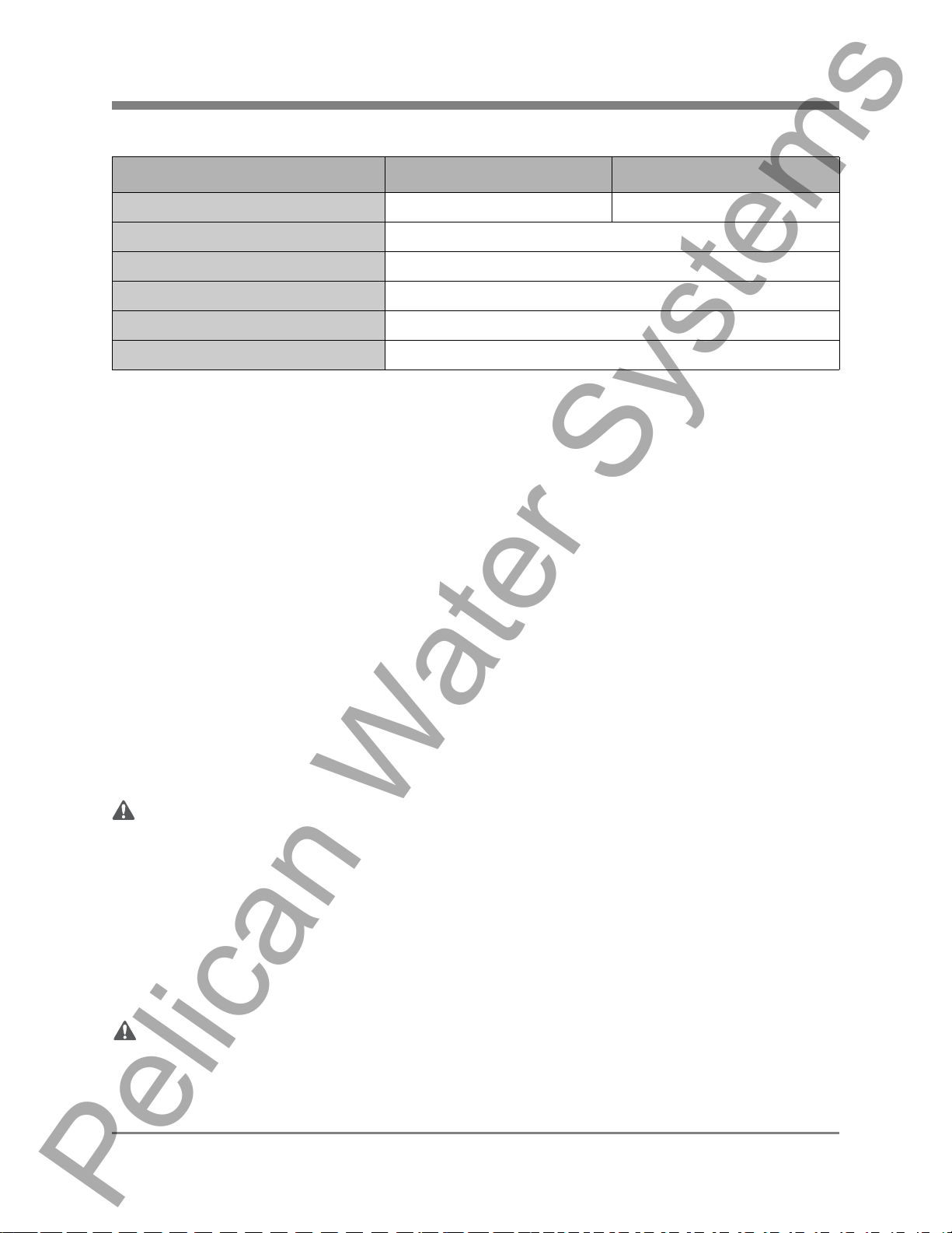
Specification Description WF6 WF10
Max Flow Rate* 10 GPM 15 GPM
Minimum Working Pressure 25 PSI
Maximum Working Pressure 80 PSI
Maximum Vacuum 5 inch/127 mm Hg
Operating Temperatures 36°F – 120°F
pH Range 7 - 11
*Minimum Rated Service Flow must be at least 6 GPM.
Important Information
Read these instructions carefully and determine the location of all system components before
beginning installation.
Check all applicable plumbing, building, and electrical codes for installation compliance.
Install the system on the main water supply.
Systems that contain electronic components cannot be installed outside in uncovered areas.
Page 4
Water Conditions for Operation
The water should be free of hydrogen sulfide, a dissolved gas with a characteristic smell of rotten
eggs. If present, it can coat the catalytic surface of the media and interfere with the process. The gas
should be removed through adequate pre-treatment.
The water should be free of hydrocarbons, oils, and lubricants. If present, they can coat the catalytic
surface of the media and interfere with the process. Remove through adequate pre-treatment.
The water should contain less than 1 mg/l of phosphates. Phosphates sequester dissolved hardness
molecules preventing them from forming crystals and may coat the catalytic media surface and
interfere with the process.
The copper level in the water supply should be below the MCL of 1.3mg/L. If copper is present above
this level, it can attach to the surface of the catalytic media and interfere with the process.
WARNING:
If this or any other system is installed in a metal (co nductive) plumbing system, i.e. copper or
galvanized metal, the plastic components of the system will interrupt the continuity of the
plumbing system. As a result any errant electricity from improperly grounded appliances
downstream or potential galvanic activity in the plumbing system can no longer ground
through contiguous metal plumbing. Older homes may have been built in accordance with
building codes from decades ago, some of which actually encouraged the grounding of
electrical appliances through the plumbing system. Consequently, the installation of a bypass
consisting of the same material as the existing plumbing, or a grounded "jumper wire"
bridging the equipment and re-establishing the contiguous conductive nature of the
plumbing system must be installed prior to your systems use.
When adding a filtration/softening system to homes/buildings supplied by well water, the system should be
installed following the pressure tank. DO NOT USE this system for pneumatic or hydro pneumatic
applications. If you are using a booster pump, then install this system following the booster
pump. If you have questions, please call customer service.
© 2011 Enviro Water Solutions, Inc.
3060 Performance Circle, Suite 2, DeLand, FL 32 72 4
www.pelicanwater.com
(877) 842-1635
WF6/WF10 Rev K —
Pelican Water Systems
Pelican WF6/WF10 Iron/Manganese Filter and Sa lt Free Soften er
Page 5
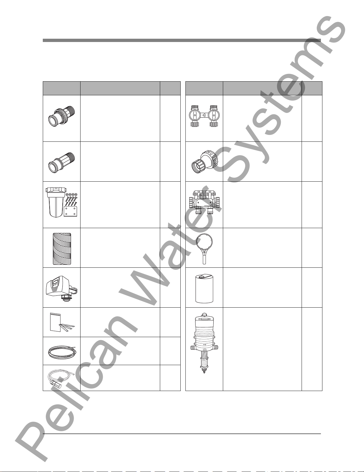
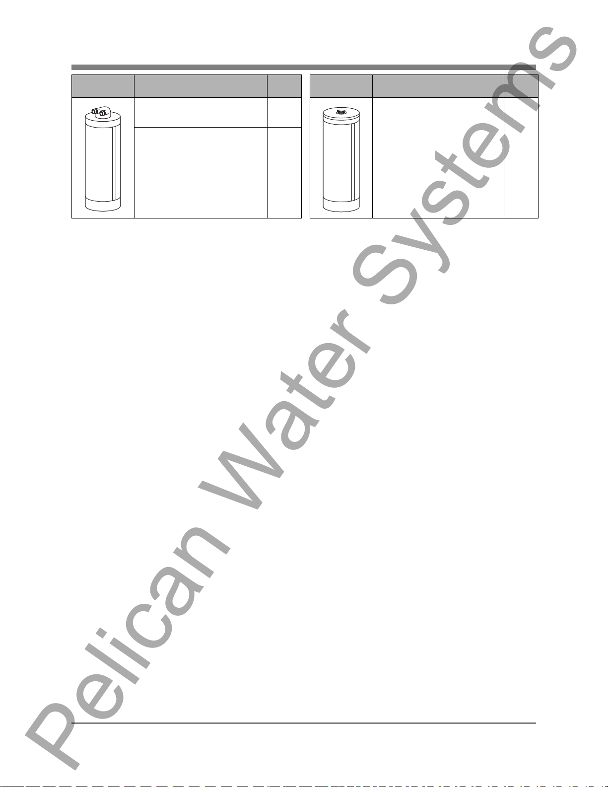
Complete Parts List
Note: Pelican supplies the parts below to accommodate a variety of water supply lines.
Table 1: Parts List
Part Description Qty. Part Description Qty.
1" Plastic Male NPT
Assembly:
V3007-04 WS1 Fitting 1"
Plastic Male NPT Assembly
(2): O-Rings (2), Split Rings
(2), and Connectors (2)
1" PVC Tail Adaptor for
Electronic Head Bypass
Pre-Filter System:
PP5 Big Blue Pre-Filter
Housing, Mounting Bracket,
Phillips Head Screws (4), Bolt
Head Screws (4), and Washers
(4)
Sediment Filter:
PC40-1 5 Micron Poly-Spun
Sediment Filter
Electronic Head 1 Solution Tank 1
2 Bypass Valve:
In/Out Bypass Valve with Red
Arrow Handles
2 Hose Bib Assembly 1
1 Bypass Valve for
Electronic Head
1 Pre-Filter Wrench 1
2
1
Chlorine Test Strips 1 Chemical Injector Pump 1
PVC Tubing Drain Line
(50 ft.)
Chemical Injector Pump
Tubing
© 2011 Enviro Water Solutions, Inc.
3060 Performance Circle, Suite 2, DeLand, FL 32 72 4
1
1
www.pelicanwater.com
(877) 842-1635
WF6/WF10 Rev K —
Pelican Water Systems
Pelican WF6/WF10 Iron/Manganese Filter and Sa lt Free Soften er
Part Description Qty. Part Description Qty.
Page 6
Pelican Whole House
Water Filter
Pelican Salt Free Water
Softener/Conditioner
Note: Drawings are not to scale.
Additional fittings will be needed to adapt to your plumbing.
1 Pelican Whole House Iron
1
1
& Manganese Filter
© 2011 Enviro Water Solutions, Inc.
3060 Performance Circle, Suite 2, DeLand, FL 32 72 4
www.pelicanwater.com
(877) 842-1635
WF6/WF10 Rev K —
Salt Free Water
Softener/Conditioner
Discharge
Line
Whole House
Water Filter
Outgoing
Water to
House
Whole House
Iron & Manganese Filter
IN
OUT
Pre-Filter
Incoming
Water
Supply
Wall Wall
Solution Tank
Electronic
Head
Chemical
Injector
Pump Tubing
Chemical Injector
Pump
Pelican Water Systems
Pelican WF6/WF10 Iron/Manganese Filter and Sa lt Free Soften er
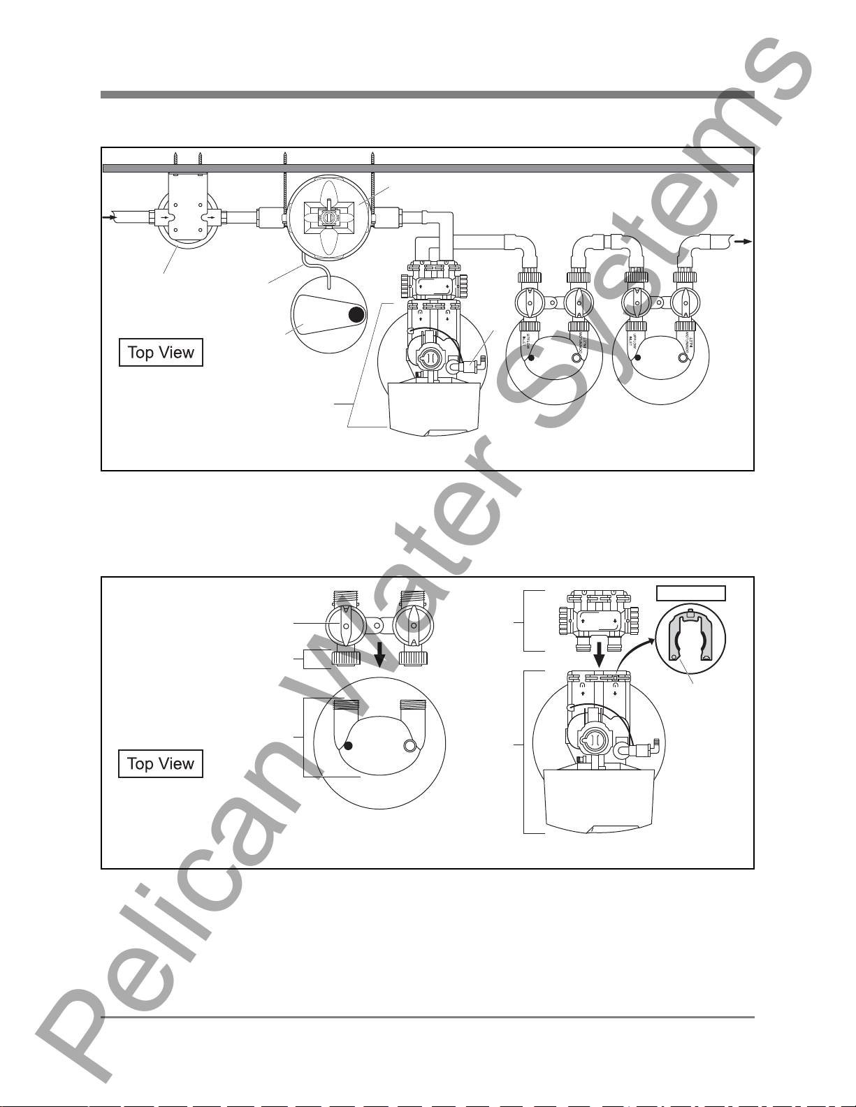
Installation Overview
Page 7
Figure 1
Pre-Installation
Bypass Valve Installation
Red Arrow
Quick
Connect Nut
UPFLOW
INLET
Water Filter
Head
Whole House Water Filter &
Salt Free Water Softener/Conditioner
Figure 2
Whole House Water Filter & Salt Free Water Softener/Conditioner - The Bypass Valve comes pre-
assembled and ready to install with the O-Rings, Split Rings, and Quick Connect Nuts. Push the Bypass
Valve into the head of the Pelican Whole House Water Filter or Salt Free Water Softener/Conditioner with
the unthreaded ends orientated towards the tank and hand-tighten the Quick Connect Nuts.
INLET
DOWNFLOW
Bypass
Valve
Electronic
Head
Iron & Manganese Filter
Front View
Red
Clip
Whole House
© 2011 Enviro Water Solutions, Inc.
3060 Performance Circle, Suite 2, DeLand, FL 32 72 4
www.pelicanwater.com
(877) 842-1635
WF6/WF10 Rev K —
Notice:
Pelican Water Systems
Pelican WF6/WF10 Iron/Manganese Filter and Sa lt Free Soften er
Whole House Iron & Manganese Filter - If the Red Clips are in the slots (female opening of Electronic
Head) remove them. Push the male O-Ring side of the Bypass Valve into the female opening of the
Electronic Head. Push the Red Clips back into the slots to tighten.
The Bypass Valve on the Electronic Head can be set to Bypass or Service by turning the knobs on the side
of the valve. If the holes are up and down then the tank is in the Bypass Mode. If the holes are side to side
then the tank is in the Service Mode. Do not remove the red clips from the Bypass Valve after connecting
to main water supply.
Note: The Whole House Water Filter and the Salt Free Softener/Conditioner flow in a different direction
than the Iron Manganese Filter. The Red Arrows on the Whole House Filter and Softener/Conditioner
Bypass may be pointing in a different direction then shown in Figure 2. If this is the case, remove the Red
Arrows by pulling them straight up. Turn them around and reposition correctly onto the Bypass Valve so
they are positioned as shown in Figure 2.
Page 8
© 2011 Enviro Water Solutions, Inc.
3060 Performance Circle, Suite 2, DeLand, FL 32 72 4
www.pelicanwater.com
(877) 842-1635
WF6/WF10 Rev K —
!IMPORTANT!
Notice:
Garden
Hose
Hose Bib
Assembly
UPFLOW
INLET
DOWNFLOW
INLET
Water
Bypass Valve
Whole House Water Filter
Pelican Water Systems
Pelican WF6/WF10 Iron/Manganese Filter and Sa lt Free Soften er
Page 9
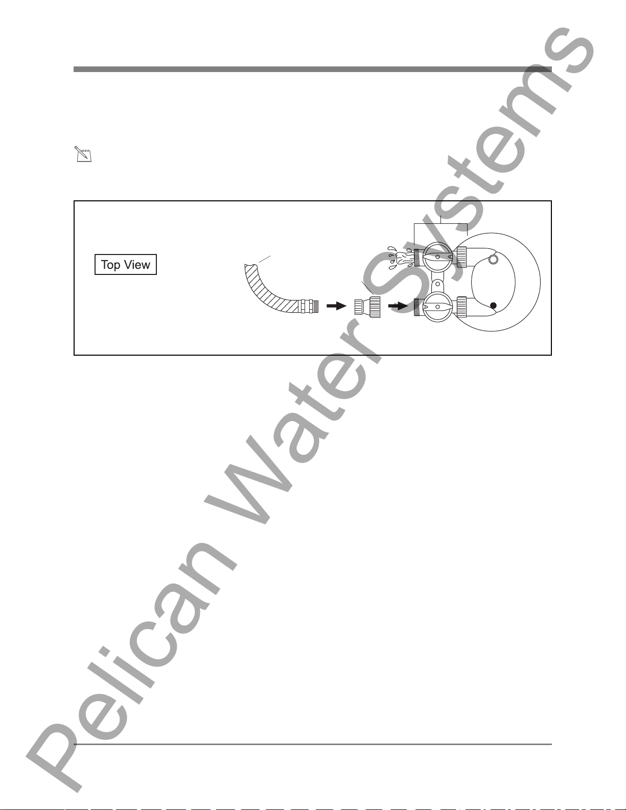
Carbon Tank Soak
Your system will not be ready for use for a minimum of 48 hours while the Carbon Soak process takes
place. Please plan your installation accordingly.
Water will flow out of the downflow inlet side of the Bypass Valve during this process. Be sure you perform
this series of steps in a location suitable for water flow.
Figure 3
1. Attach a garden hose to the Hose Bib Assembly.
2. Connect the Hose Bib Assembly to the upflow inlet side of the Bypass Valve and hand tighten.
3. Fill the Pelican Whole House Water Filter Tank full until water comes out of downflow inlet side of
the Bypass Valve.
4. Turn the water off.
5. Remove the garden hose from the Hose Bib Assembly. Do not remove the fitting.
6. Allow the carbon tank to soak for at least 48 hours prior to tank installation.
© 2011 Enviro Water Solutions, Inc.
3060 Performance Circle, Suite 2, DeLand, FL 32 72 4
www.pelicanwater.com
(877) 842-1635
 Loading...