

Pelican PLUS50 Installation Manual

Caution
Failure to follow these instructions can damage the product or cause a hazardous
condition. Disconnect power during the installation of this product. All wiring must
conform to local codes and ordinances. This product is designed for use with 24
VAC systems.
For additional assistance visit www.PelicanWireless.com to request support.
Introduction
The plus50 provides a hardware upgrade to add CO2 sensor capability to existing
Pelican thermostats including the TS200 and TS200H. Once installed, the
thermostat will provide continuous status of CO2 levels and can provide demand
ventilation in three ways:
1. Control of the Pelican Pearl Economizer Controller.
2. In coordination with Pelican's line of Zone Controllers with integrated
Economizer Control.
3. Simple fan operation when CO2 levels exceed the CO2 set point.
Prerequisites
Existing Pelican thermostats will not recognize the CO2 sensor unless they are
running at least firmware version 3.0. We recommend verifying the firmware version
before beginning installation. Contact Pelican Technical Support at
support@PelicanWireless.com or 888-512-0490 for assistance verify the firmware
version and if necessary to receive the free firmware upgrade.
Installation
The plus50 is provided as a replacement sub-base. The existing thermostat front
plate and internal Wiring Module (WM500 or WM700) will need to be installed into
the new sub-base. For installations where the Wiring Module has already been
relocated to a different location the new sub-base can replace the existing sub-base
without removing and re-installing the Wiring Module.
The installation steps are:
1. Turn off power to the thermostat.
2. Remove the existing front plate by pulling it straight away from the base.
3. Disconnect all control wiring.
4. Remove the existing Wiring Module as shown in the following section.
5. Remove the existing sub-base and install the new sub-base.
6. Re-install the Wiring Module into the new sub-base.
7. Reconnect control wiring. Re-install the thermostat front plate.
Installation Guide
PLUS50 integrated CO
2
Sensor
1
Wiring Module Removal and Installation
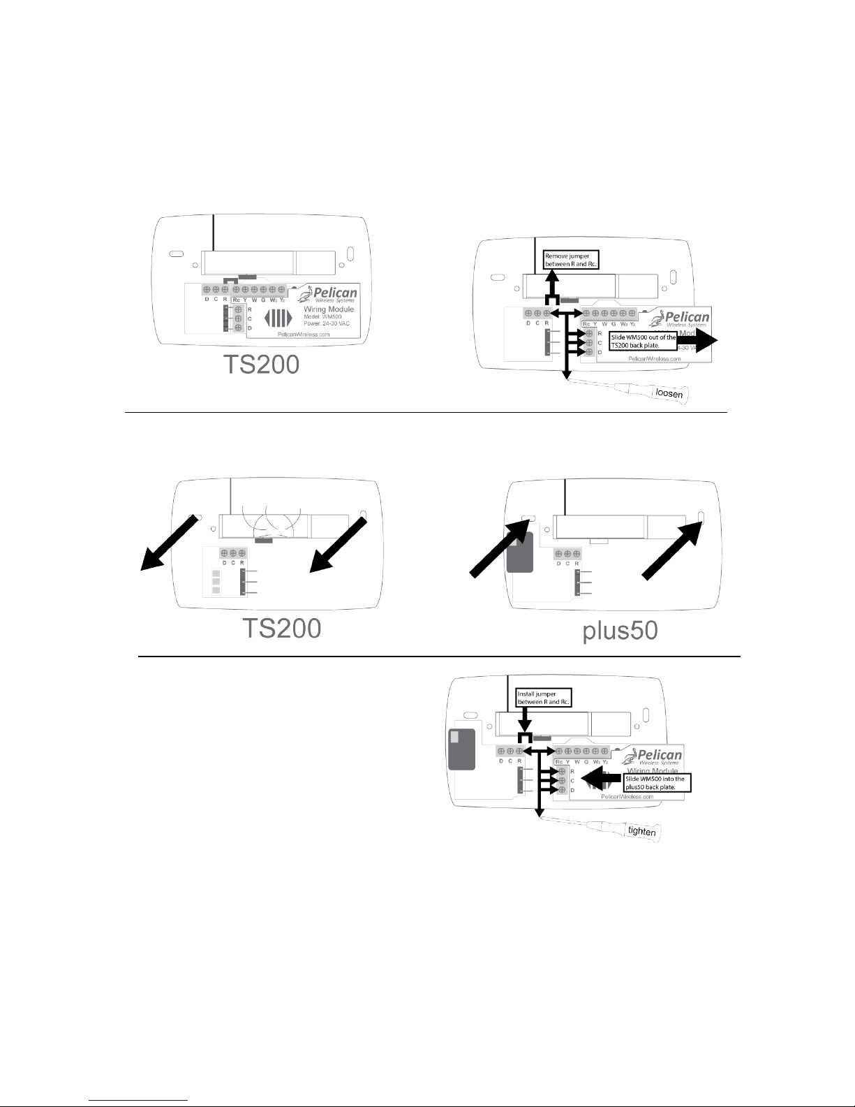
The following diagram shows how to remove the Wiring Module and then re-install
the Wiring Module into the new plus50 sub-base.
Integrated CO2 Sensor Operation
The integrated CO2 sensor never requires manual calibration. It has a built-in
automatic calibration which will adjust the CO2 accuracy after 48 hours of operation.
The thermostat will display CO2 levels on the Site Manager Web App after 3 minutes
of operation. Demand Ventilation parameters can be adjusted using the Site
Manager Thermostat Setup function.
Step 1: Pull front plate off
TS200 or TS200H.
Step 2: Loosen R and Rc terminals
and remove jumper. Loosen R, C, D
terminals on Wiring Module. Slide
Wiring Module to the right to
remove.
Step 3: Remove existing TS200
or TS200H sub-base from wall.
Step 4: Mount plus50 sub-base
onto wall.
Step 5: Install Wiring Module
into plus50 sub-base. Install
jumper between R and Rc.
Tighten R and Rc terminals.
Tighten R, D, C terminals on
Wiring Module.
2
 Loading...