

Pelican PEARL Installation Manual
PEARL Economizer Controller
Pelican
Wireless Systems
Installation Guide
Pelican Wireless Systems, 2655 Collier Canyon Rd. Livermore, CA 94551
Phone: 888.512.0490
Email: support@pelicanwireless.com Website: www.PelicanWireless.com

Caution
The PEARL is an add-on accessory to the Pelican thermostat
(TS200 or TS250). It provides inputs, outputs and logic that allow
for intelligent economization and demand ventilation control.
The PEARL is designed to control most 24VAC HVAC systems,
including: gas, electric, oil, heat pump, and forced air. It is also
designed to control 0-10VDC variable speed fans and modulating
economizer damper actuators.
Failure to follow these instructions or improper installation,
service, adjustments, maintenance, and/or use can result in
personal injury, damage to personal property, and/or cause a
hazardous and dangerous situation. Consult a qualified installer,
distributor, or Pelican Wireless Systems for assistance or support.
Follow all safety codes and regulations and all local and state
building codes. Read instructions thoroughly and follow any
warnings or notes.
Disconnect power during the installation of this product. All wiring
must conform to local and state codes and ordinances. The
PEARL is designed to communicate with Pelican products only.
This guide is designed to assist Pelican Certified Contractors on
installing the PEARL for economizer damper control and/or
demand control ventilation applications. For Certification
assistance or other support questions contact Pelican Support at
888.512.0490.
Compatibility
1

Table of Contents
2
Installation and Mounting
Wiring
Start Up
Status Lights
Actuator Calibration
Setup and Configuration
Troubleshooting
Sequence of Operations
3
6
15
16
17
18
20
21
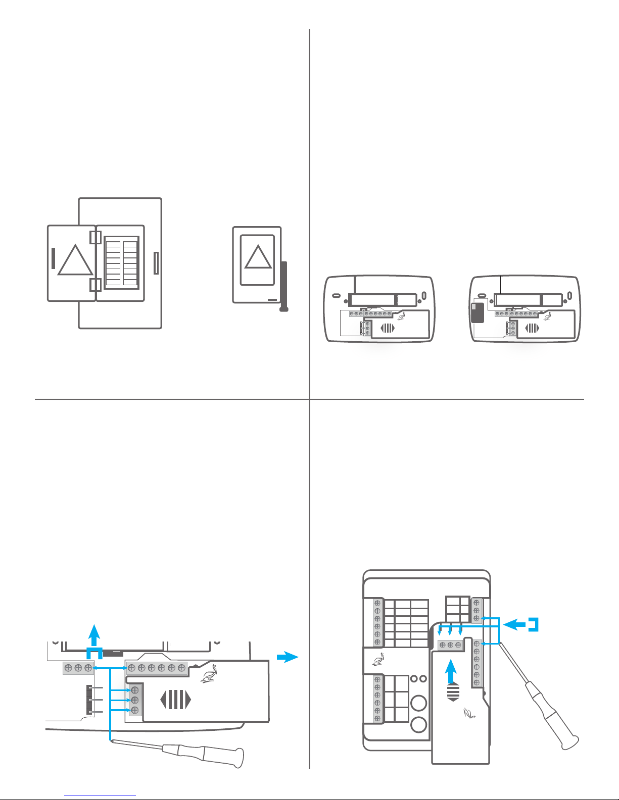
Begin by removing the cover of
your Pelican Thermostat
(TS200 or TS250). To remove
the cover, gently pull the
thermostat faceplate away from
the back plate.
Rc
CD R
R
C
D
Y W G W Y2 2
TS200
or
Pelican
Wireless Systems
Wiring Module
Model: WM500
Power: 24-30 VAC
PelicanWireless.com
Rc
CD R
R
C
D
Y W G W Y
2 2
TS250
Pelican
Wireless Systems
Wiring Module
Model: WM500
Power: 24-30 VAC
PelicanWireless.com
Electrical Panel Electrical Switch
or
This will protect you, the HVAC
equipment, and prevent
electrical faults. This step is
required for safety.
1. Switch off power
on
off
Loosen the R and Rc terminals
to remove the jumper (save
jumper). Loosen R, C, D
terminals on WM500. Gently
slide WM500 to the right to
remove.
3. Remove the wire
module (WM500) from
the thermostat base
CD R
Rc
R
C
D
Y W G W Y2 2
Pelican
Wireless Systems
Wiring Module
Model: WM500
Power: 24-30 VAC
PelicanWireless.com
Gently push WM500 all the way
into the PEARL. Install jumper
between R and Rc and tighten.
Tighten R, C, D terminals on
WM500.
4. Insert the WM500
into the PEARL
Pearl
Economizer
Controller
D
C
R
A1
A2
E
C
S1
S2
ACT
AUX
ENA
COM
POS
EXT
0-10 Out
0-10 Out
24V Out
0-10 In
0-10 In
DATA
COM
PWR
T1
T2
T3
SAT
RAT
OAT
STATUS
MOVE
TEST
Pelican
Wireless Systems
Rc Y W G W2 Y2
R C D
PelicanWireless.com
Pelican
Wireless Systems
Wiring Module
Model: WM500
Power: 24-30 VAC
loosen
tighten
2. Remove the Pelican
thermostat faceplate
3
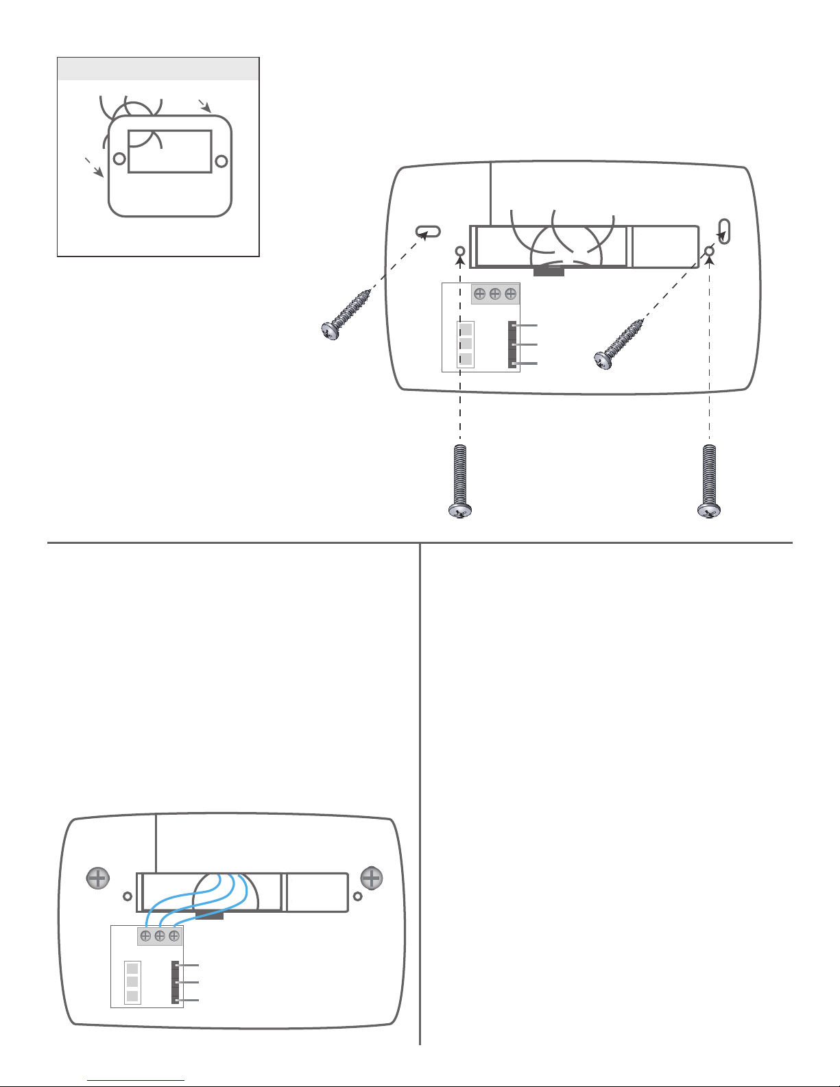
Old thermostat
CD R
Remove old thermostat
5. Mount thermostat
sub-base onto the wall
Option Two:
mount on horizontal
electrical box
Option One:
standard mounting holes
(use dry wall anchors if
needed)
Record which wires used for
each terminal. These wires will
connect to the same terminals
at the PEARL.
6. Connect 3 unique
wires to D, C, and R
terminals
Line up the three pin male
connector on the thermostat
faceplate’s electrical board with
the three pin female connector
on the thermostat sub-base.
Gently press the thermostat
front plate onto the mounted
sub-base.
7. Attach thermostat
faceplate
CD R
4
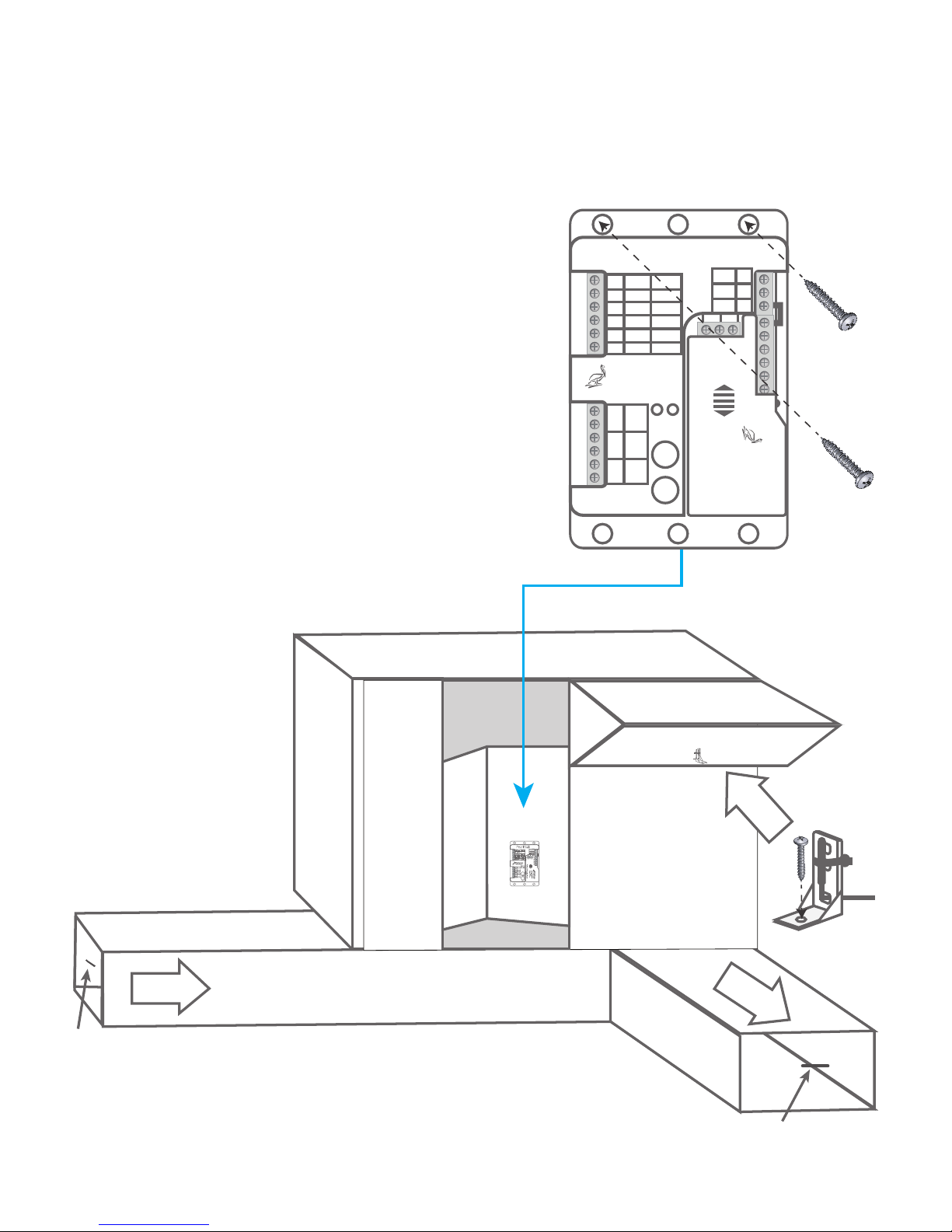
The PEARL should be mounted inside
the HVAC equipment or enclosed in a
water tight location. Mount in a location
with easy access to control wiring and
service.
Inside HVAC
unit
Supply Air
Temperature
Probe
Return Air
Temperature
Probe
PEARL
Economizer
Pearl
Economizer
Controller
D
C
R
A1
A2
E
C
S1
S2
ACT
AUX
ENA
COM
POS
EXT
0-10 Out
0-10 Out
24V Out
0-10 In
0-10 In
DATA
COM
PWR
T1
T2
T3
SAT
RAT
OAT
STATUS
MOVE
TEST
Pelican
Wireless Systems
Rc Y W G W2 Y2
R C D
PelicanWireless.com
Pelican
Wireless Systems
Wiring Module
Model: WM500
Power: 24-30 VAC
Outside
Air Probe
Mounted in
Economizer
8. Install the PEARL inside the HVAC
equipment
5
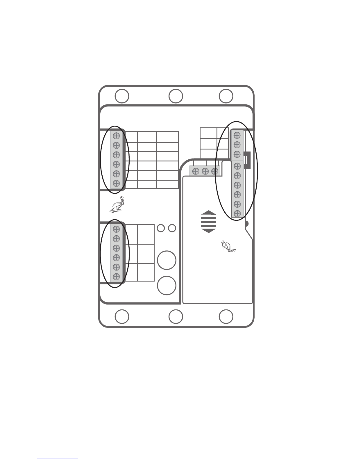
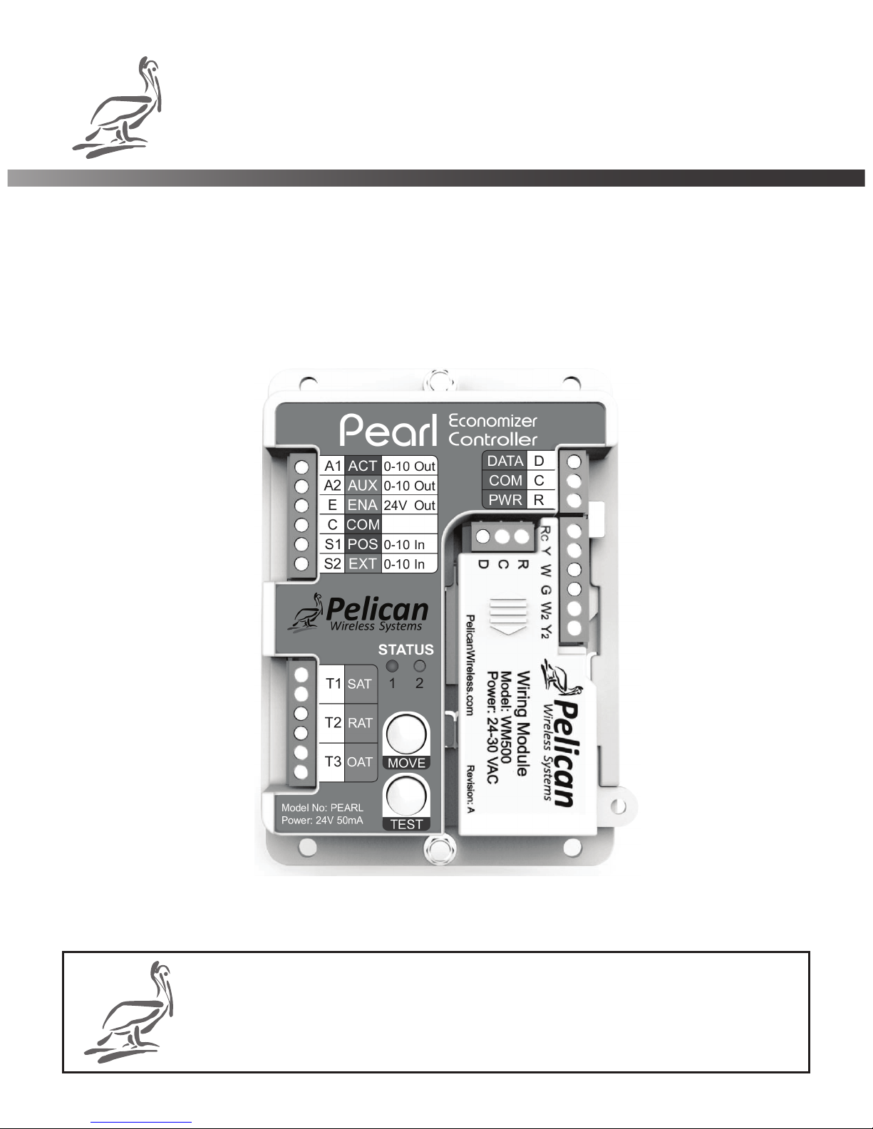
The PEARL has three terminal blocks. Refer to
the following charts and wiring diagrams for
proper connections.
Pearl
Economizer
Controller
D
C
R
A1
A2
E
C
S1
S2
ACT
AUX
ENA
COM
POS
EXT
0-10 Out
0-10 Out
24V Out
0-10 In
0-10 In
DATA
COM
PWR
T1
T2
T3
SAT
RAT
OAT
STATUS
MOVE
TEST
Pelican
Wireless Systems
Rc Y W G W2 Y2
R C D
PelicanWireless.com
Pelican
Wireless Systems
Wiring Module
Model: WM500
Power: 24-30 VAC
Right
Terminal Block
Left-Bottom
Terminal Block
Left-Top
Terminal Block
6
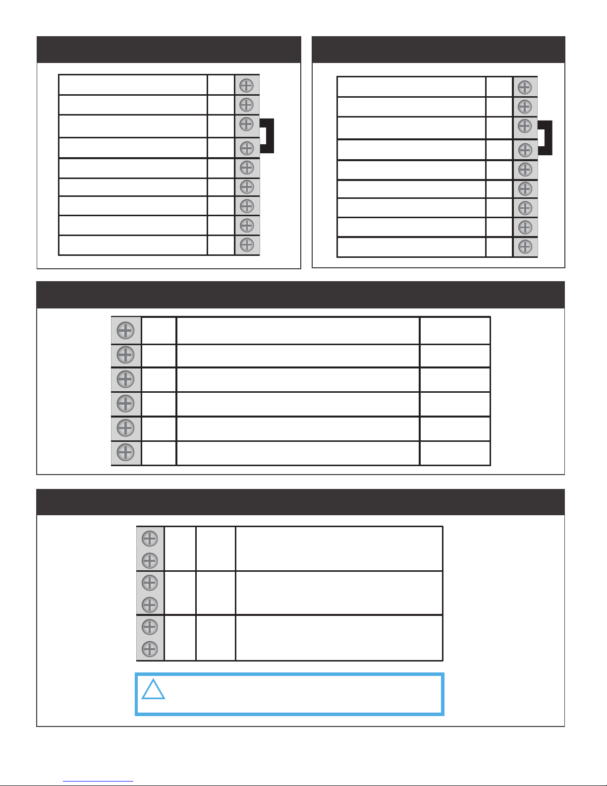
Heat Pump Control (Right Terminals)Conventional Control (Right Terminals)
ECONOMIZER ACTUATOR (output)
VARIABLE FREQUENCY DRIVE (output)
24VAC ENABLE OUTPUT
COMMON
ACTUATOR FEEDBACK (input)
0-10VDC INPUT
A1
A2
E
C
S1
S2
0-10 Out
0-10 Out
24V Out
NEUTRAL
0-10 In
0-10 In
T1
T2
T3
SAT
RAT
OAT
SUPPLY TEMPERATURE
RETURN TEMPERATURE
OUTSIDE AIR TEMPERATURE
CAUTION: Do NOT connect 24V or any
other electrical voltage to these terminals.
!
Economizer and VFD Control (Left-Top Terminal Block)
10K Type II Temperature Probe Inputs (Left-Bottom Terminal Block)
D
C
R
DATA
COMMON
24VAC PWR
24VAC
Rc
Y
W
G
COOL STAGE 1
HEAT STAGE 1
FAN or 24V VFD ENABLE
W2
Y2
HEAT STAGE 2
COOL STAGE 2
D
C
R
DATA
COMMON
24VAC PWR
24VAC
Rc
Y
W
G
COMPRESSOR STAGE 1
REVERSING VALVE (O/B)
FAN or 24V VFD ENABLE
W2
Y2
AUXILIARY HEAT
COMPRESSOR STAGE 2
7
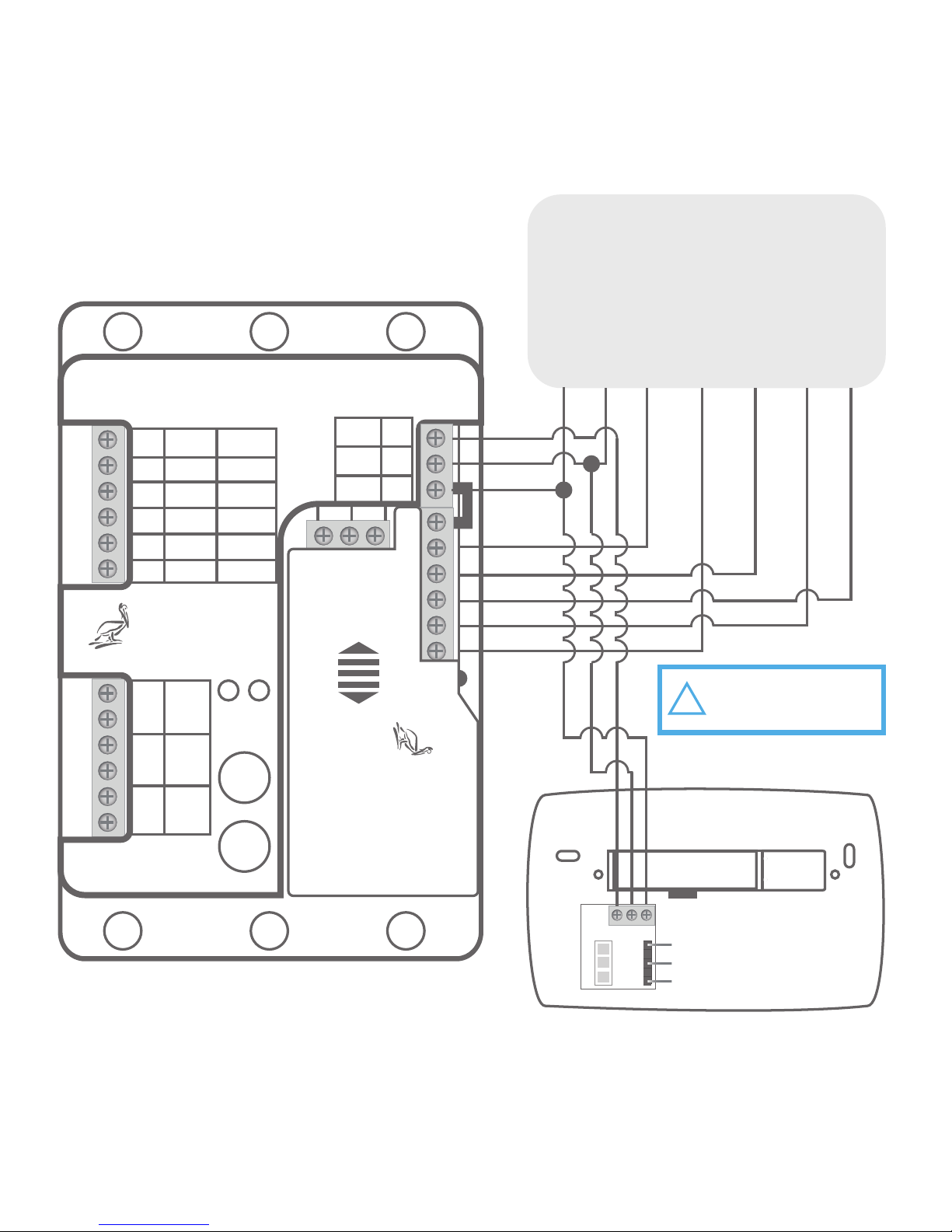
Conventional Unit Wiring
(Right Terminal Block)
Pearl
Economizer
Controller
D
C
R
A1
A2
E
C
S1
S2
ACT
AUX
ENA
COM
POS
EXT
0-10 Out
0-10 Out
24V Out
0-10 In
0-10 In
DATA
COM
PWR
T1
T2
T3
SAT
RAT
OAT
STATUS
MOVE
TEST
Pelican
Wireless Systems
Rc Y W G W2 Y2
R C D
PelicanWireless.com
Pelican
Wireless Systems
Wiring Module
Model: WM500
Power: 24-30 VAC
ROOF TOP UNIT
R
C
Y1 W1 G
Y2 W2
CD R
THERMOSTAT
NOTE: "G" 24V output
can also be used to
enable a VFD.
!
8

Pearl
Economizer
Controller
D
C
R
A1
A2
E
C
S1
S2
ACT
AUX
ENA
COM
POS
EXT
0-10 Out
0-10 Out
24V Out
0-10 In
0-10 In
DATA
COM
PWR
T1
T2
T3
SAT
RAT
OAT
STATUS
MOVE
TEST
Pelican
Wireless Systems
Rc Y W G W2 Y2
R C D
PelicanWireless.com
Pelican
Wireless Systems
Wiring Module
Model: WM500
Power: 24-30 VAC
ROOF TOP UNIT
R
C
Y1 O/B G
Y2 AUX
CD R
THERMOSTAT
NOTE: "G" 24V output
can also be used to
enable a VFD.
!
Heat Pump Unit Wiring
(Right Terminal Block)
9
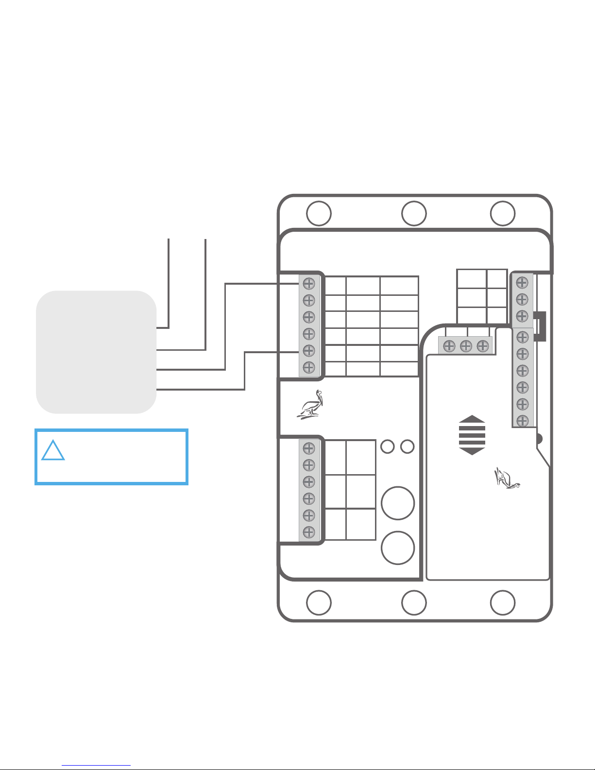
Economizer Actuator Wiring
(Left-Top Terminal Block)
Economizer Actuator
Connect actuator power to
the same 24VAC power
source as the PEARL.
Pearl
Economizer
Controller
D
C
R
A1
A2
E
C
S1
S2
ACT
AUX
ENA
COM
POS
EXT
0-10 Out
0-10 Out
24V Out
0-10 In
0-10 In
DATA
COM
PWR
T1
T2
T3
SAT
RAT
OAT
STATUS
MOVE
TEST
Pelican
Wireless Systems
Rc Y W G W2 Y2
R C D
PelicanWireless.com
Pelican
Wireless Systems
Wiring Module
Model: WM500
Power: 24-30 VAC
1
2
3
4
- Common
+ Hot
0-10VDC In
0-10VDC Out
NOTE: Actuator position
feedback (S1) is required
for Fault Detection and
Auto-Configuration.
!
10
 Loading...