

Pelican OmniRO Installation Manual

Drinking Water Systems
R
everse
O
smosis
Installation
Manual
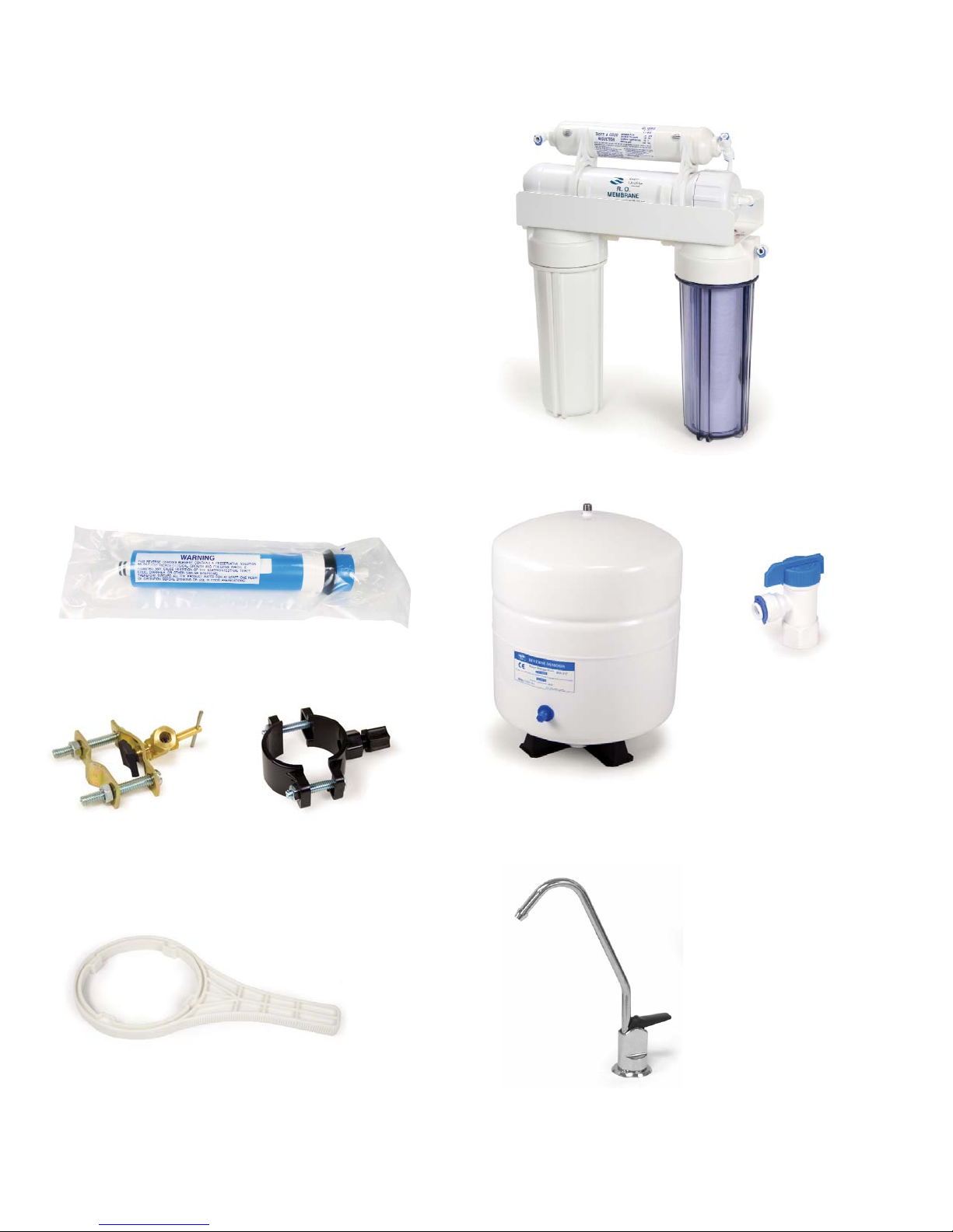
Reverse Osmosis Package Content
4-Stage Reverse Osmosis Assembly
Reverse Osmosis Membrane
Feed Water
Saddle Valve
Drain Saddle Valve
Faucet Package
Filter Housing Wrench
Drinking Water Storage Tank
Storage Tank
Shut-Off Ball Valve

SECTION I. INTRODUCTION
Congratulations, you have just purchased one of
the finest Reverse Os mo sis Drinking Water
Appliances avail able.
Like any other fine product, this ap pli ance requires
periodic maintenance in accordance with the schedule outlined below.
Recommended Filter Change Schedule*
1 - Pre-filter, 10", 5 Micron 6 Months
2 - Granulated Activated Carbon 6 Months
Post-filter
3 - Reverse Osmosis Membrane 24 - 36 Months
4 - Pre-Carbon Filter For Chlorine 6 Months
Removal
5 - Inline Carbon Adsorbtion Filter 6 Months
*Based on standard conditions.
Your new Reverse Osmosis (R.O.) Drinking Wa ter
sys tem uses a combination of filtration tech nol o gies
to reduce unwanted contaminants in a water sup ply.
The following steps combine to give you the best in
clear sparkling drinking water:
MECHANICAL FILTRATION - The sediment pre-filter will remove the larger particles such as silt, rust
and scale. Its 5 micron (equal to 0.0002 inch) nominal rating helps to give maximum life to the R.O.
Mem brane and carbon filter.
ACTIVATED CARBON PRE FILTER(S) - The activated carbon in a pre-filter will remove any chlorine
that may be present in the feed water.
This pretreatment is also necessary for membrane pro tec tion in chlorinated water.
REVERSE OSMOSIS MEMBRANE - The R.O. Mem brane is the heart of the filtration system. It is
designed to reduce the dissolved mineral content of the
water. Minerals picked up in the environment by the
water are measured as Total Dissolved Solids (T.D.S.).
In the Reverse Osmosis process, dissolved min er als
are sep a rat ed from the incoming water (Feed Wa ter) to
pro duce the product water (the Permeate). The excess
minerals are rinsed to drain (the Reject Water). The
spiral wound construction of the R.O. Membrane
pro vides max i mum surface area for water
production and is less sus cep ti ble to fouling by par tic u late matter, turbidity and col loi dal materials.
ACTIVATED CARBON POST FILTER - The Ac ti vat ed
Carbon Post Filter cartridge contains carbon particles with a vast network of pores. The tre men dous
surface area of these pores (typically 800-1200
square meters per gram of carbon) gives the carbon
very good ad sorp tive sites for chlorine as well as
other substances that contribute to tastes and
odors. The product water from the membrane as
well as the holding tank passes through the
Activated Carbon Post filter on the way to the
Dispensing Faucet. The Activated Carbon Post
Filter reduces tastes and odors that may pass
through the system. It adds a final “polish” to the
water.
INLINE CARBON ADSORPTION FIL TER - This slow
flow carbon filter is designed to reduce certain
organic compounds and chloramines.
AUTOMATIC SHUT-OFF VALVE - The A.S.O.
Valve sens es when the product water tank is full
and clos es the feed water supply to prevent excess
reject water from going to drain when the unit is not
pro duc ing water.
SECTION II: PREPARATION
A. Major System Components
The following components comprise the R.O. Drink ing Water System
1. A Reverse Osmosis assembly consisting of the
white alu mi num bracket, filter hous ings,
automatic shut-off, mem brane module and an
in-line carbon filter.
2. A drinking water holding tank.
3. A faucet kit.
4. A plastic tubing kit with self-piercing saddle
valve and drain clamp.
5. Other items necessary for installation may
include wood screws or ma chine screws for
mounting the R.O. assembly, or concrete an chors for hang ing on base ment wall,
additional tubing or tube con nec tors, plastic
wire ties for or ga niz ing tubing.
Note:
For systems equipped with Quick Connect fittings, see last page.

B. Tools Recommended for In stal la tion
The following tools will cover most of the in stal la tion sites encountered:
• 3/8" variable speed electric drill.
• Extension work light with outlet.
• Safety Glasses.
• 1-1/4" porcelain hole cutter kit.
• 1-1/4" Greenlee hole punch and 1/8" and 1/2"
metal drill bits for pilot hole.
• Center punch and hammer.
• 1-1/4" wood bit.
• Assorted wood and metal drill bits including
7/32" metal drill bit.
• Phillips head and flat blade screwdrivers.
• 1/2", 9/16" and 5/8" open end wrench.
• 10" Crescent wrench with jaws taped to hold
faucet.
• Teflon tape.
• Wide masking tape or duct tape.
• Plastic tubing cutter.
• Extra plastic tubing.
• Low range air pressure gauge.
• Bicycle hand air pump.
• Small bottle of liquid chlorine bleach.
C. Determine System Location
The R.O. system can be located under a sink or in a
basement depending on space availability and the
cus tom er’s preference. If a basement installation is
se lect ed, additional tubing, hardware and fittings
may be needed and a hole will have to be made from
in side the cabinet, through the floor, to the basement.
Nev er install in an area of the home where tem per a ture is freezing as damage to the system will result.
Considerations for an ice maker or other remote
hook up should be determined, including rout ing and
any ad di tion al tools, fittings, and tub ing that may
be re quired.
1. Faucet - The faucet should be placed near the
sink where drinking water is normally
obtained. Con ve nience of use (filling of water
pitchers and glass es), and an open area
beneath the faucet under the sink for attaching
product tubing are considerations.
A 2" di am e ter flat surface is re quired above
and be low the mounting site. The thick ness of
the mount ing surface should not exceed 1-1/4".
Watch for strengthening web bing on the un der side of cast iron sinks.
2. Drinking Water Holding Tank - The hold ing
tank may be placed where it is convenient
within 10 feet of the faucet, under the sink or
in an adjacent cabinet are best choic es. If a
longer run of tubing is required, the tubing
should be the 1/2" di am e ter O.D. size to pre vent a high pres sure drop. Re mem ber, these
tanks can weigh up to 30 pounds when full of
water , a firm, level area is required.
3. R.O Assembly - The R.O. Assembly may be
mount ed on either the right or left side of the
under-sink area or a cabinet. Mounting in the
basement is also an option, one possible location is near the laundry /utility sink where cold
potable water and drain access is handy. The
mounting location should allow adequate clear ance and ac ces si bil i ty for car tridge changes.
4. Feed Water Connection - The self-pierc ing feed
water shut off valve should be located as close
to the R.O. as sem bly as possible. USE A
POTABLE COLD WA TER SUPPLY ONLY.
Softened water is pre ferred as it will ex tend
the life of the R.O. Mem brane.
5. Drain Connection - The drain saddle assembly
is designed to fit around a standard 1-1/2" OD
drain pipe. The drain saddle should always be
installed above (before) the trap and on the
vertical or hor i zon tal tail piece. Never install
the drain saddle close to the outlet of a garbage
disposal or plug ging of the RO drain line may
occur. If discharging into an util i ty sink or
standpipe, an air gap of greater than 1" above
the flood rim must be pro vid ed. Do NOT connect the system drain line to the dishwasher
drain or near the garbage disposal.
D. Prepare The Area For Installation
To save time it is often advised to call the customer
and request they clear under the sink prior to
arrival. Oth er wise, remove supplies from under the
sink and stack them neatly away from the work ing
area. Ar range a light for the work area, if necessary.
If a basement installation is called for, de ter mine
where components will be located and how they will
be mounted. Special mounting brack ets and
hardware may be nec es sary to secure the system to
a wall or ceiling joists.
Inspect cold water supply line and drain to de ter mine if any special fittings, in addition to what is
included in the kit, are required.
 Loading...