

Pelican GW400 Installation Manual

Firewall Settings
The Pelican Wireless Gateway requires the ability to make outbound
TCP connections from the local network to the Internet. If you are using
the New Site Setup and are receiving the message “Invalid serial
number or unreachable Gateway”, the gateway may be having difficulty
registering itself on the Internet. The following instructions can be
provided to your IT department to resolve Firewall issues.
By default the Gateway will request a local IP address using DHCP. This
is identical to any standard computer or laptop which is attached to the
local network. Alternatively the Gateway can be given a static IP
address (Contact Pelican Technical Support for assistance in setting a
static address). The Gateway does not require a public IP address and
does not require any inbound ports to be opened on the Firewall. The
Gateway will need to initiate 2 outbound TCP connections through the
Firewall. The first one is on port 9742. The second one will be assigned
to the Gateway once it makes its first connection to the Pelican Servers.
This second port will be in the range of 9800-11000.
Pelican recommends modifying the firewall configuration to allow
unrestricted outbound connections based on the MAC address of the
Wireless Gateway. The MAC address is printed on the side of the
Gateway.
If network security policy is more restricted, the firewall configuration can
be modified to either allow outbound connections on the range of ports
listed above or to restrict the connections to ports 9742 and the
assigned port. Once port 9742 has been opened contact Pelican
Technical support at to find out the unique port which has been defined
for your site.
Installation Guide
GW400 Wireless Gateway
The Wireless Gateway provides communication between the
Pelican products installed at your site and the Internet. The
Pelican devices communicate wirelessly with the Gateway. The
Internet connection is established through the Ethernet port on
the Gateway.
The Gateway does not require a public IP address and does not
require any inbound ports to be opened on the Firewall. Sites
with more restrictive Firewall settings may need additional
Firewall configurations. See the section labeled “Firewall
Settings” at the end of this guide for a complete explanation.
Wall Mounting
The Wireless Gateway is designed to be wall mounted using the
included 3M Command Removable Strips or using the screw
mount on the rear of the unit.
Find a suitable location which is:
Within 6 feet of an electrical outlet
At least 4 feet away from other wireless devices
Away from large metal objects which may interfere with
the wireless signal
Above office equipment which may interfere with the
wireless signal
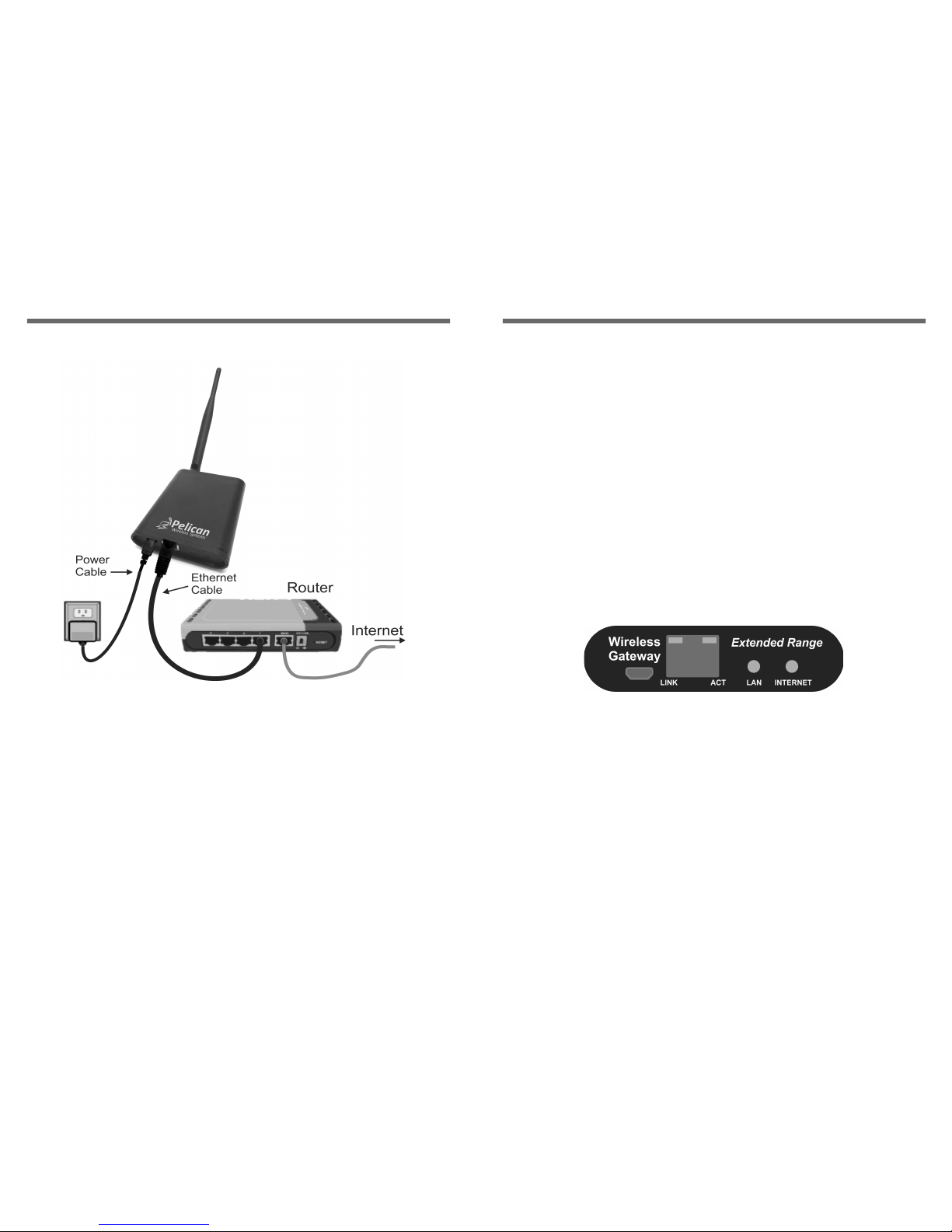
Installation Diagram
Installation Steps (See diagram)
1. Attach the Command Strip to the back of the Wireless Gateway.
2. Insert the included Ethernet cable into the port on the Wireless
Gateway.
3. Insert the other end of the Ethernet cable into a free port on the
back of your Internet router (Note: The Wireless Gateway can
alternately be connected to any Ethernet port at your site which
has Internet access).
4. Insert the power cable from the included power adapter into the
Wireless Gateway.
5. Plug the power adapter into an electrical outlet.
6. Attach the Wireless Gateway to the wall using the Command
Strip you attached to the back of the unit.
Site Setup
Once your newly installed Wireless Gateway is connected and powered
up, you are ready to perform the initial site setup. This is done using the
Pelican “New Site Wizard”.
You will need the Serial Number printed on the side of your Wireless
Gateway to complete the setup.
The New Site Wizard can be found using your browser and going to
www.PelicanWireless.com. Then select the “New Site Setup” tab on the
Pelican home page.
Follow the Instructions on the New Site Wizard page to complete your
setup and begin accessing and programming your thermostats.
Status Indicator Lights
There are 4 indicator lights on the gateway. Two are directly above the
RJ-45 Ethernet connector. They are labeled LINK and ACT. The other
two indicators are labeled LAN and INTERNET.
The indicators have the following meanings:
LAN
Off – No Power
Fast Blink – Power Up (1 second)
Slow Blink – Getting IP Configuration (DHCP)
Solid On – Local Configuration Complete (LAN Active)
INTERNET
Off – Waiting for LAN
Slow Blink – Trying to reach Cloud Servers
Solid On – Internet Active (Connected to Cloud Server)
LINK – Ethernet Link Status
ACT – Ethernet Activity Indicator
 Loading...