

Page 1

ADDENDUM
Addendum No. C2262M-A
Date October 1, 2012
®
Documents Affected C3444M-A Spectra
Operation/Configuration manual (pp. 11 and 25)
C3434M-C Spectra
manual (pp. 23, 68, and 69)
C3463M-C Spectra
Installation/Operation manual (pp. 1, 8, 18, 24 to 26, 30, 34, 36, 39, 41,
43, 46, 55, 64, and 65)
C3462M Spectra
Quick Start guide (pp. 1 and 10)
Document Update This addendum describes changes to model numbers, component
numbers, and camera/optics specifications.
Changes to Spectra IV Model/Component Numbers
• All 35X models have been replaced by 36X models. For example, SD4E35-F0 has been replaced
by SD4E36-F0.
• All references to TXB-IP have been replaced with TXB-N.
• The following component model numbers have changed:
IV IP Series Dome System
®
IV SE Horizon Series Dome Drive
®
IV SL and Spectra IV SE Series
®
IV SL and Spectra IV SE Series Dome Systems
Obsolete 35X
Component Model Number
DD4CBW35 (NTSC) DD436 (NTSC)
DD4CBW35-X (PAL) DD436-X (PAL)
Obsolete 27X
Component Model Number
DD427 (NTSC) DD429 (NTSC)
DD427-X (PAL) DD429-X (PAL)
Replacement 36X
Component Model Number
Replacement 29X
Component Model Number
Page 2
Changes to Spectra IV Product Specifications
Feature
Obsolete 35X
Specifications
Replacement 36X
Specifications
Lens Local Length 3.4 mm 3.3 mm
Zoom 35X optical 36X optical
Horizontal Angle of View 55.8° at 3.4 mm wide zoom 57.2° at 3.3 mm wide zoom
Feature
Obsolete 27X
Specifications
Replacement 29X
Specifications
Lens Focal Length 91.8 mm 98.6 mm
Zoom 27X optical 29X optical
Horizontal Angle of View 2.3° at 91.8 mm telephoto zoom 1.7° at 98.8 mm telephoto zoom
REVISION HISTORY
REVISION HISTORY DO NOT COPY TEXT FROM THIS TEXT BOX - PLACEHOLDER INFO ONLY!
Document # Date Comments
Manual # Date Comments
C2262M 5/12 Original version.
CxxxxM x/xx Original version.
C2262M-A 10/12 Reformatted document size.
The materials used in the manufacture of this document and its components are compliant to
the requirements of Directive 2002/95/EC.
Pelco, the Pelco logo, and other trademarks associated w ith Pelco products referred to in this publication are trademarks of Pelco, Inc. or its affiliates.
All other product names and services are the property of their respective companies.
Product specifications and availability are subject to change without notice.
© Copyright 2012, Pelco, Inc. All rights rese rved.
Pelco by Schneider Electric 3500 Pelco Way Clovis, California 93612-5699 United States
USA & Canada Tel (800) 289-9100 Fax (800) 289-9150
International Tel +1 (559) 292-1981 Fax +1 (559) 348-1120
www.pelco.com www.pelco.com/community
C2262M-A (9/12)
Page 3
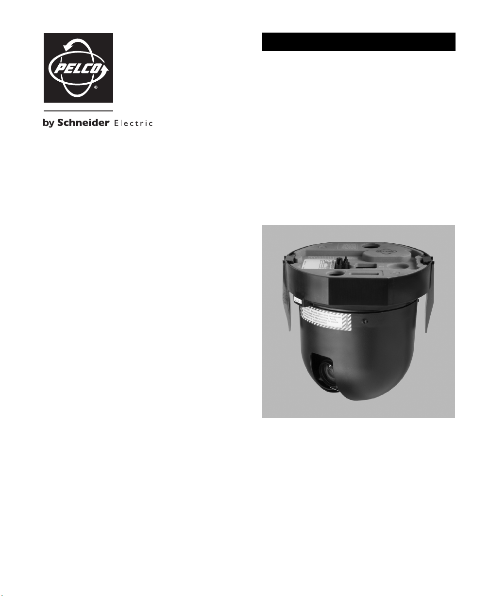
QUICK START
Spectra® IV SL and
Spectra IV SE Series
Dome Systems
23X, 27X, and 35X Models
C3462M (9/09)
Page 4
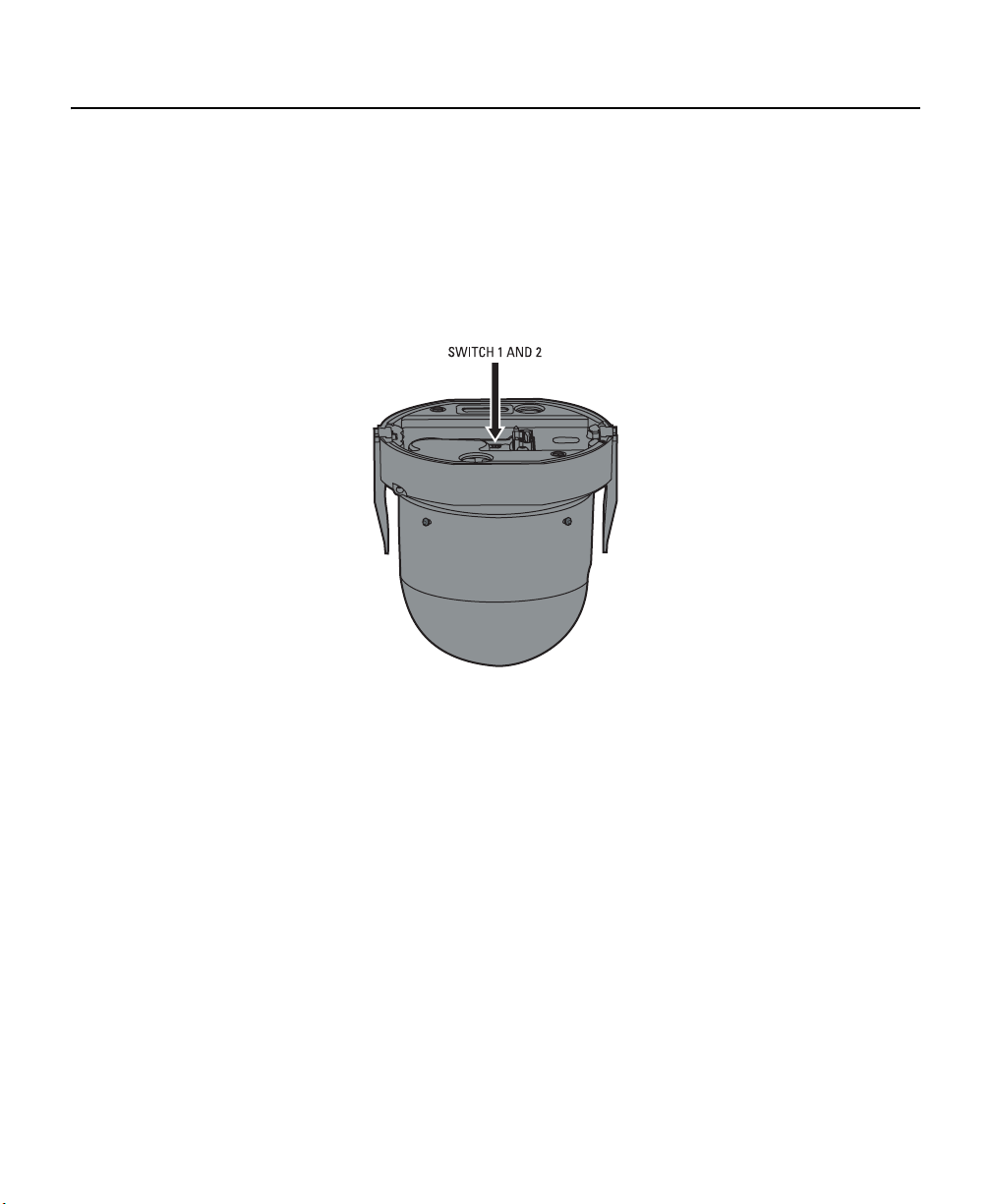
Installing the Dome Drive
1. Perform one of the following options:
• View video using both analog and IP connections: Set the DIP switches on the top of the Spectra IV dome
drive (refer to Figure 12). For DIP switch settings, refer to the labels located on the top of the dome drive, or refer
to Switch Settings on page 3.
• View video using the IP connection: If your dome drive is part of a Spectra IV IP system, you do not need to
set the DIP switches.
NOTE: When connecting more than one Spectra IV dome to a single controller, terminate the unit farthest from the
controller. To terminate the dome drive set the SW2-10 switch to the ON position.
Figure 1. Setting the DIP Switches
2. Install the dome drive into the back box.
a. Align the blue and red tabs with the blue and red labels on the back box.
b. Push in the red tab and insert that side of the dome drive first.
c. Push in the blue tab and insert the dome drive into the back box the remainder of the way.
d. Continue pushing on the ends of the tabs until both sides click firmly into place.
2 C3462M (9/09)
Page 5

SWITCH SETTINGS
WARNING: If you are using Pelco D-type or P-type control, your system may not operate if the baud rate and
address switches are not set correctly. The switches are set at the factory at the defaults for Pelco D-type control
(2400 baud and address 1).
Special Systems
Switch Number 12345678910
AD-32 Preset System ON
CM9502 Setting ON
Pelco Coaxitron Controller OFF
Third-Party Coaxial Control ON
Third-Party Pelco P-type Control ON
Serial Port Settings
Switch Number 12345678910
RS422 OFF OFF
RS485, 4-Wire OFF ON
RS485, 2-Wire ON ON
Pelco D or P Protocol Baud Rate
Switch Number 12345678910
2400 Baud (Default for D-type Control) OFF OFF OFF
4800 Baud (Default for P-type Control) ON OFF OFF
9600 Baud OFF ON OFF
Table A. Switch Settings for SW2
Video Cable Type
Switch Number 12345678910
Coaxial Cable OFF
UTP Cable ON
Dome Termination
Switch Number 12345678910
Ter mi na te d ON
Not Terminated OFF
C3462M (9/09) 3
Page 6

Table B. Switch Settings for SW1, P-Type Control
NOTE: For Coaxitron controls, SW1 is not used; set all switches to OFF. For D-type control systems, refer to Table C.
SPECTRA
ADDRESS
1 OFF OFF OFF OFF OFF
2 ON OFF OFF OFF OFF
3 OFF ON OFF OFF OFF
4 ON ON OFF OFF OFF
5 OFF OFF ON OFF OFF
6 ON OFF ON OFF OFF
7 OFF ON ON OFF OFF
8 ON ON ON OFF OFF
9 OFF OFF OFF ON OFF
10 ON OFF OFF ON OFF
11 OFF ON OFF ON OFF
12 ON ON OFF ON OFF
13 OFF OFF ON ON OFF
14 ON OFF ON ON OFF
15 OFF ON ON ON OFF
16 ON ON ON ON OFF
SW1-1 SW1-2 SW1-3 SW1-4 SW1-5
SWITCH SETTING
Table C. Switch Settings for SW1, D-Type Control
NOTE: For Coaxitron controls, SW1 is not used; set all switches to OFF. For P-type control systems, refer to Table B.
SPECTRA
ADDRESS
SW1-1 SW1-2 SW1-3 SW1-4 SW1-5 SW1-6 SW1-7 SW1-8
1 ON OFF OFF OFF OFF OFF OFF OFF
2 OFF ON OFF OFF OFF OFF OFF OFF
3 ON ON OFF OFF OFF OFF OFF OFF
4 OFF OFF ON OFF OFF OFF OFF OFF
5 ON OFF ON OFF OFF OFF OFF OFF
6 OFF ON ON OFF OFF OFF OFF OFF
7 ON ON ON OFF OFF OFF OFF OFF
8 OFF OFF OFF ON OFF OFF OFF OFF
9 ON OFF OFF ON OFF OFF OFF OFF
10 OFF ON OFF ON OFF OFF OFF OFF
11 ON ON OFF ON OFF OFF OFF OFF
12 OFF OFF ON ON OFF OFF OFF OFF
13 ON OFF ON ON OFF OFF OFF OFF
14 OFF ON ON ON OFF OFF OFF OFF
15 ON ON ON ON OFF OFF OFF OFF
SWITCH SETTING
SPECTRA
ADDRESS
17 OFF OFF OFF OFF ON
18 ON OFF OFF OFF ON
19 OFF ON OFF OFF ON
20 ON ON OFF OFF ON
21 OFF OFF ON OFF ON
22 ON OFF ON OFF ON
23 OFF ON ON OFF ON
24 ON ON ON OFF ON
25 OFF OFF OFF ON ON
26 ON OFF OFF ON ON
27 OFF ON OFF ON ON
28 ON ON OFF ON ON
29 OFF OFF ON ON ON
30 ON OFF ON ON ON
31 OFFONONONON
32 ON ON ON ON ON
SPECTRA
ADDRESS
16 OFF OFF OFF OFF ON OFF OFF OFF
17 ON OFF OFF OFF ON OFF OFF OFF
18 OFF ON OFF OFF ON OFF OFF OFF
19 ON ON OFF OFF ON OFF OFF OFF
20 OFF OFF ON OFF ON OFF OFF OFF
21 ON OFF ON OFF ON OFF OFF OFF
22 OFF ON ON OFF ON OFF OFF OFF
23 ON ON ON OFF ON OFF OFF OFF
24 OFF OFF OFF ON ON OFF OFF OFF
25 ON OFF OFF ON ON OFF OFF OFF
26 OFF ON OFF ON ON OFF OFF OFF
27 ON ON OFF ON ON OFF OFF OFF
28 OFF OFF ON ON ON OFF OFF OFF
29 ON OFF ON ON ON OFF OFF OFF
30 OFF ON ON ON ON OFF OFF OFF
SW1-1 SW1-2 SW1-3 SW1-4 SW1-5
SW1-1 SW1-2 SW1-3 SW1-4 SW1-5 SW1-6 SW1-7 SW1-8
SWITCH SETTING
SWITCH SETTING
4 C3462M (9/09)
Page 7

SPECTRA
ADDRESS
SW1-1 SW1-2 SW1-3 SW1-4 SW1-5 SW1-6 SW1-7 SW1-8
31 ON ON ON ON ON OFF OFF OFF
32 OFF OFF OFF OFF OFF ON OFF OFF
33 ON OFF OFF OFF OFF ON OFF OFF
34 OFF ON OFF OFF OFF ON OFF OFF
35 ON ON OFF OFF OFF ON OFF OFF
36 OFF OFF ON OFF OFF ON OFF OFF
37 ON OFF ON OFF OFF ON OFF OFF
38 OFF ON ON OFF OFF ON OFF OFF
39 ON ON ON OFF OFF ON OFF OFF
40 OFF OFF OFF ON OFF ON OFF OFF
41 ON OFF OFF ON OFF ON OFF OFF
42 OFF ON OFF ON OFF ON OFF OFF
43 ON ON OFF ON OFF ON OFF OFF
44 OFF OFF ON ON OFF ON OFF OFF
45 ON OFF ON ON OFF ON OFF OFF
46 OFF ON ON ON OFF ON OFF OFF
47 ON ON ON ON OFF ON OFF OFF
48 OFF OFF OFF OFF ON ON OFF OFF
49 ON OFF OFF OFF ON ON OFF OFF
50 OFF ON OFF OFF ON ON OFF OFF
51 ON ON OFF OFF ON ON OFF OFF
52 OFF OFF ON OFF ON ON OFF OFF
53 ON OFF ON OFF ON ON OFF OFF
54 OFF ON ON OFF ON ON OFF OFF
55 ON ON ON OFF ON ON OFF OFF
56 OFF OFF OFF ON ON ON OFF OFF
57 ON OFF OFF ON ON ON OFF OFF
58 OFF ON OFF ON ON ON OFF OFF
59 ON ON OFF ON ON ON OFF OFF
60 OFF OFF ON ON ON ON OFF OFF
61 ON OFF ON ON ON ON OFF OFF
62 OFF ON ON ON ON ON OFF OFF
63 ON ON ON ON ON ON OFF OFF
64 OFF OFF OFF OFF OFF OFF ON OFF
65 ON OFF OFF OFF OFF OFF ON OFF
66 OFF ON OFF OFF OFF OFF ON OFF
67 ON ON OFF OFF OFF OFF ON OFF
68 OFF OFF ON OFF OFF OFF ON OFF
69 ON OFF ON OFF OFF OFF ON OFF
70 OFF ON ON OFF OFF OFF ON OFF
SWITCH SETTING
SPECTRA
ADDRESS
SW1-1 SW1-2 SW1-3 SW1-4 SW1-5 SW1-6 SW1-7 SW1-8
71 ON ON ON OFF OFF OFF ON OFF
72 OFF OFF OFF ON OFF OFF ON OFF
73 ON OFF OFF ON OFF OFF ON OFF
74 OFF ON OFF ON OFF OFF ON OFF
75 ON ON OFF ON OFF OFF ON OFF
76 OFF OFF ON ON OFF OFF ON OFF
77 ON OFF ON ON OFF OFF ON OFF
78 OFF ON ON ON OFF OFF ON OFF
79 ON ON ON ON OFF OFF ON OFF
80 OFF OFF OFF OFF ON OFF ON OFF
81 ON OFF OFF OFF ON OFF ON OFF
82 OFF ON OFF OFF ON OFF ON OFF
83 ON ON OFF OFF ON OFF ON OFF
84 OFF OFF ON OFF ON OFF ON OFF
85 ON OFF ON OFF ON OFF ON OFF
86 OFF ON ON OFF ON OFF ON OFF
87 ON ON ON OFF ON OFF ON OFF
88 OFF OFF OFF ON ON OFF ON OFF
89 ON OFF OFF ON ON OFF ON OFF
90 OFF ON OFF ON ON OFF ON OFF
91 ON ON OFF ON ON OFF ON OFF
92 OFF OFF ON ON ON OFF ON OFF
93 ON OFF ON ON ON OFF ON OFF
94 OFF ON ON ON ON OFF ON OFF
95 ON ON ON ON ON OFF ON OFF
96 OFF OFF OFF OFF OFF ON ON OFF
97 ON OFF OFF OFF OFF ON ON OFF
98 OFF ON OFF OFF OFF ON ON OFF
99 ON ON OFF OFF OFF ON ON OFF
100 OFF OFF ON OFF OFF ON ON OFF
101 ON OFF ON OFF OFF ON ON OFF
102 OFF ON ON OFF OFF ON ON OFF
103 ON ON ON OFF OFF ON ON OFF
104 OFF OFF OFF ON OFF ON ON OFF
105 ON OFF OFF ON OFF ON ON OFF
106 OFF ON OFF ON OFF ON ON OFF
107 ON ON OFF ON OFF ON ON OFF
108 OFF OFF ON ON OFF ON ON OFF
109 ON OFF ON ON OFF ON ON OFF
110 OFF ON ON ON OFF ON ON OFF
SWITCH SETTING
C3462M (9/09) 5
Page 8

SPECTRA
ADDRESS
SW1-1 SW1-2 SW1-3 SW1-4 SW1-5 SW1-6 SW1-7 SW1-8
111 ON ON ON ON OFF ON ON OFF
112 OFF OFF OFF OFF ON ON ON OFF
113 ON OFF OFF OFF ON ON ON OFF
114 OFF ON OFF OFF ON ON ON OFF
115 ON ON OFF OFF ON ON ON OFF
116 OFF OFF ON OFF ON ON ON OFF
117 ON OFF ON OFF ON ON ON OFF
118 OFF ON ON OFF ON ON ON OFF
119 ON ON ON OFF ON ON ON OFF
120 OFF OFF OFF ON ON ON ON OFF
121 ON OFF OFF ON ON ON ON OFF
122 OFF ON OFF ON ON ON ON OFF
123 ON ON OFF ON ON ON ON OFF
124 OFF OFF ON ON ON ON ON OFF
125 ON OFF ON ON ON ON ON OFF
126 OFF ON ON ON ON ON ON OFF
127 ON ON ON ON ON ON ON OFF
128 OFF OFF OFF OFF OFF OFF OFF ON
129 ON OFF OFF OFF OFF OFF OFF ON
130 OFF ON OFF OFF OFF OFF OFF ON
131 ON ON OFF OFF OFF OFF OFF ON
132 OFF OFF ON OFF OFF OFF OFF ON
133 ON OFF ON OFF OFF OFF OFF ON
134 OFF ON ON OFF OFF OFF OFF ON
135 ON ON ON OFF OFF OFF OFF ON
136 OFF OFF OFF ON OFF OFF OFF ON
137 ON OFF OFF ON OFF OFF OFF ON
138 OFF ON OFF ON OFF OFF OFF ON
139 ON ON OFF ON OFF OFF OFF ON
140 OFF OFF ON ON OFF OFF OFF ON
141 ON OFF ON ON OFF OFF OFF ON
142 OFF ON ON ON OFF OFF OFF ON
143 ON ON ON ON OFF OFF OFF ON
144 OFF OFF OFF OFF ON OFF OFF ON
145 ON OFF OFF OFF ON OFF OFF ON
146 OFF ON OFF OFF ON OFF OFF ON
147 ON ON OFF OFF ON OFF OFF ON
148 OFF OFF ON OFF ON OFF OFF ON
149 ON OFF ON OFF ON OFF OFF ON
150 OFF ON ON OFF ON OFF OFF ON
SWITCH SETTING
SPECTRA
ADDRESS
SW1-1 SW1-2 SW1-3 SW1-4 SW1-5 SW1-6 SW1-7 SW1-8
151 ON ON ON OFF ON OFF OFF ON
152 OFF OFF OFF ON ON OFF OFF ON
153 ON OFF OFF ON ON OFF OFF ON
154 OFF ON OFF ON ON OFF OFF ON
155 ON ON OFF ON ON OFF OFF ON
156 OFF OFF ON ON ON OFF OFF ON
157 ON OFF ON ON ON OFF OFF ON
158 OFF ON ON ON ON OFF OFF ON
159 ON ON ON ON ON OFF OFF ON
160 OFF OFF OFF OFF OFF ON OFF ON
161 ON OFF OFF OFF OFF ON OFF ON
162 OFF ON OFF OFF OFF ON OFF ON
163 ON ON OFF OFF OFF ON OFF ON
164 OFF OFF ON OFF OFF ON OFF ON
165 ON OFF ON OFF OFF ON OFF ON
166 OFF ON ON OFF OFF ON OFF ON
167 ON ON ON OFF OFF ON OFF ON
168 OFF OFF OFF ON OFF ON OFF ON
169 ON OFF OFF ON OFF ON OFF ON
170 OFF ON OFF ON OFF ON OFF ON
171 ON ON OFF ON OFF ON OFF ON
172 OFF OFF ON ON OFF ON OFF ON
173 ON OFF ON ON OFF ON OFF ON
174 OFF ON ON ON OFF ON OFF ON
175 ON ON ON ON OFF ON OFF ON
176 OFF OFF OFF OFF ON ON OFF ON
177 ON OFF OFF OFF ON ON OFF ON
178 OFF ON OFF OFF ON ON OFF ON
179 ON ON OFF OFF ON ON OFF ON
180 OFF OFF ON OFF ON ON OFF ON
181 ON OFF ON OFF ON ON OFF ON
182 OFF ON ON OFF ON ON OFF ON
183 ON ON ON OFF ON ON OFF ON
184 OFF OFF OFF ON ON ON OFF ON
185 ON OFF OFF ON ON ON OFF ON
186 OFF ON OFF ON ON ON OFF ON
187 ON ON OFF ON ON ON OFF ON
188 OFF OFF ON ON ON ON OFF ON
189 ONOFFONONONONOFFON
190 OFF ON ON ON ON ON OFF ON
SWITCH SETTING
6 C3462M (9/09)
Page 9

SPECTRA
ADDRESS
SW1-1 SW1-2 SW1-3 SW1-4 SW1-5 SW1-6 SW1-7 SW1-8
191 ON ON ON ON ON ON OFF ON
192 OFF OFF OFF OFF OFF OFF ON ON
193 ON OFF OFF OFF OFF OFF ON ON
194 OFF ON OFF OFF OFF OFF ON ON
195 ON ON OFF OFF OFF OFF ON ON
196 OFF OFF ON OFF OFF OFF ON ON
197 ON OFF ON OFF OFF OFF ON ON
198 OFF ON ON OFF OFF OFF ON ON
199 ON ON ON OFF OFF OFF ON ON
200 OFF OFF OFF ON OFF OFF ON ON
201 ON OFF OFF ON OFF OFF ON ON
202 OFF ON OFF ON OFF OFF ON ON
203 ON ON OFF ON OFF OFF ON ON
204 OFF OFF ON ON OFF OFF ON ON
205 ON OFF ON ON OFF OFF ON ON
206 OFF ON ON ON OFF OFF ON ON
207 ON ON ON ON OFF OFF ON ON
208 OFF OFF OFF OFF ON OFF ON ON
209 ON OFF OFF OFF ON OFF ON ON
210 OFF ON OFF OFF ON OFF ON ON
211 ON ON OFF OFF ON OFF ON ON
212 OFF OFF ON OFF ON OFF ON ON
213 ON OFF ON OFF ON OFF ON ON
214 OFF ON ON OFF ON OFF ON ON
215 ON ON ON OFF ON OFF ON ON
216 OFF OFF OFF ON ON OFF ON ON
217 ON OFF OFF ON ON OFF ON ON
218 OFF ON OFF ON ON OFF ON ON
219 ON ON OFF ON ON OFF ON ON
220 OFF OFF ON ON ON OFF ON ON
221 ON OFF ON ON ON OFF ON ON
222 OFF ON ON ON ON OFF ON ON
SWITCH SETTING
SPECTRA
ADDRESS
SW1-1 SW1-2 SW1-3 SW1-4 SW1-5 SW1-6 SW1-7 SW1-8
223 ON ON ON ON ON OFF ON ON
224 OFF OFF OFF OFF OFF ON ON ON
225 ON OFF OFF OFF OFF ON ON ON
226 OFF ON OFF OFF OFF ON ON ON
227 ON ON OFF OFF OFF ON ON ON
228 OFF OFF ON OFF OFF ON ON ON
229 ON OFF ON OFF OFF ON ON ON
230 OFF ON ON OFF OFF ON ON ON
231 ON ON ON OFF OFF ON ON ON
232 OFF OFF OFF ON OFF ON ON ON
233 ON OFF OFF ON OFF ON ON ON
234 OFF ON OFF ON OFF ON ON ON
235 ON ON OFF ON OFF ON ON ON
236 OFF OFF ON ON OFF ON ON ON
237 ON OFF ON ON OFF ON ON ON
238 OFF ON ON ON OFF ON ON ON
239 ON ON ON ON OFF ON ON ON
240 OFF OFF OFF OFF ON ON ON ON
241 ON OFF OFF OFF ON ON ON ON
242 OFF ON OFF OFF ON ON ON ON
243 ON ON OFF OFF ON ON ON ON
244 OFF OFF ON OFF ON ON ON ON
245 ON OFF ON OFF ON ON ON ON
246 OFF ON ON OFF ON ON ON ON
247 ON ON ON OFF ON ON ON ON
248 OFF OFF OFF ON ON ON ON ON
249 ON OFF OFF ON ON ON ON ON
250 OFF ON OFF ON ON ON ON ON
251 ON ON OFF ON ON ON ON ON
252 OFF OFF ON ON ON ON ON ON
253 ONOFFONONONONONON
254 OFF ON ON ON ON ON ON ON
SWITCH SETTING
C3462M (9/09) 7
Page 10

Preset 95: Accessing the Main Menu
You can call up the main menu on your monitor by programming (setting or creating) preset 95 (preset 28 in AD32-preset
mode).
Programming preset 95 for Pelco’s controllers varies according to the type of controller you are using. Instructions for
programming preset 95 are given below for various Pelco controllers. Refer to the instructions shipped with your controller
for more information.
CM6700/CM6800
1. Enter the number of the Spectra IV dome system and press the CAM key.
2. Enter 95 and hold the PRESET key for two seconds.
3. In the Edit Preset menu, go to SET and press the ACK key. The main menu appears.
KBD200A/KBD300A DIRECT MODE ONLY
1. Enter 95.
2. Hold the PRESET key (approximately five seconds) until the main menu appears on the screen.
CM9500
1. Enter the number of the Spectra IV dome system and press the CAM key. The main menu appears.
2. Highlight SETUP in the main menu and press the SELECT key.
3. Highlight CAM in the Setup menu and press the SELECT key.
4. Highlight PRESET in the Camera menu and press the SELECT key.
5. Enter 95 and press the F1 key. The main menu appears.
CM9740/CM9760/CM9770/CM9780
1. Press the ESCAPE key to open the main menu. Select DEF. The Define submenu appears.
2. Enter your four-digit PIN if this is your first time entering this mode.
3. Enter 95 and select PRST. The main menu appears on the monitor.
4. Select the Quit icon to return to the default menu.
KBD4000/KBD4002
1. Press the SPOT MONITOR key.
2. Enter 95, then hold the PRESET key (approximately five seconds) until the main menu appears on the screen.
8 C3462M (9/09)
Page 11

MPT9500
Extended Coaxitron or RS-485 Mode
1. Enter 95 and press the PRESET SET key.
2. Press the F2 key. The main menu appears.
NET300/NET350/NET4001A
1. Check the Set box.
2. Click the preset 95 button. The main menu appears.
ENDURA WORKSTATION
1. Right-click in the video pane of the Spectra IV dome system.
2. Click Preset and then click Select Preset.
3. Enter 95 and then click OK.
VCD5000
1. Enter 95 for the preset action. The shortcuts menu appears.
2. Press the Preset button on the KBD5000.
DX4100/DX4500/DX4600/DX8100
1. Click the PTZ button on the toolbar. The PTZ control appears.
2. Click the Program button on the PTZ control. The main menu appears.
DIGITAL SENTRY® SYSTEM SOFTWARE
1. Click the PTZ tab.
2. Click the right or left arrows below the "Go to Preset" button until "Go to Preset 95" appears on the button.
3. Click the "Go to Preset 95" button. The main menu appears.
DIGITAL SENTRY DS CONTROLPOINT
1. Click the PTZ Controls icon. The PTZ Control tab appears below the PTZ video frame.
2. Click the up and down arrows to display 95 in the Preset Name text box.
3. Click the Call button. The main menu appears.
DVR5100
1. While in live view mode, select a video pane that is displaying video from a Spectra IV dome system.
2. From the Main menu, click Actions. The Actions menu appears.
3. From the Actions menu, click PTZ Operations. The PTZ Operations dialog box appears.
4. In the PTZ Operations dialog box, type 95 in the text box, and then click Presets. The main menu appears.
C3462M (9/09) 9
Page 12

Troubleshooting
To use your dome, refer to the installation and operation/configuration manuals on the resource disc.
If the following instructions fail to solve your problem, contact Pelco Product Support at 1-800-289-9100 (USA and Canada)
or +1-559-292-1981 (international) for assistance. Be sure to have the serial number available when calling.
Do not try to repair the unit yourself. Leave maintenance and repairs to qualified technical personnel only.
Problem Possible Causes Suggested Resolution
Dome does not start properly
after installation.
Dome starts correctly, but you
do not have accurate control
No video is displayed. Power is not connected. Check the power connector.
Spectra IV information
(model, firmware, Pelco P and
Pelco D protocol addresses,
and communication settings)
does not appear after the
configuration cycle.
The displayed video is
scrambled.
Table D. Troubleshooting the Spectra IV Dome System
The circuit board fuse may
need to be replaced.
The back box may not be
receiving proper voltage.
Switch settings on the dome
drive are set incorrectly.
.
Video cable is not connected. Check the video connector.
Video UTP cable is not
connected.
TXB-IP module is not inserted
properly in the back box.
The unit cannot complete its
configuration cycle.
Video UTP wires are
incorrectly installed in the
back box.
Check the fuse on the circuit board inside the back box for
continuity. Replace the fuse if needed.
Check the wiring with a volt meter to ensure that the back box is
receiving proper voltage.
Check the signal with a volt meter or an oscilloscope.
NOTE: This step will not apply if you are using Coaxitron control.
Ensure that the switch settings on the dome drive are set correctly
(refer to Switch Settings on page 3.)
Ensure that the proper back box wiring was used and that the
polarity of wiring is correct.
Check the UTP connector.
If you are using a Spectra IV IP dome system, reinstall the TXB-IP
module. Make sure the pins on the module are inserted correctly.
Ensure that nothing is physically obstructing the pan and tilt
movement of the dome drive.
Verify that the video UTP cable is wired correctly to the UTP
connector on the back box circuit board. The blue wire should be
connected to the positive terminal, and the gray wire should be
connected to the negative terminal (refer to the installation
manual on the resource disc).
10 C3462M (9/09)
Page 13

PRODUCT WARRANTY AND RETURN INFORMATION
WARRANTY
Pelco will repair or replace, without charge, any merchandise proved defective in
material or workmanship for a period of one year after the date of shipment.
Exceptions to this warranty are as noted below:
• Five years:
– Fiber optic products
– TW3000 Series unshielded twisted pair (UTP) transmission products
– CC3701H-2, CC3701H-2X, CC3751H-2, CC3651H-2X, MC3651H-2, and
MC3651H-2X camera models
• Three years:
– Pelco-designed fixed network cameras and network dome cameras
– Pelco-branded fixed camera models (CCC1390H Series, C10DN Series,
– EH1500 Series enclosures
– Spectra
– Camclosure
– DX Series digital video recorders, DVR5100 Series digital video
– Endura
– Genex
™
technology.
with Sarix
C10CH Series, and IP3701H Series)
®
IV products (including Spectra IV IP)
®
Series (IS, ICS, IP) integrated camera systems
®
recorders, Digital Sentry
video recorders, and NVR300 Series network video recorders
®
Series distributed network-based video products
®
Series products (multiplexers, server, and keyboard)
Series hardware products, DVX Series digital
– PMCL200/300/400 Series LCD monitors
• Two years:
– Standard varifocal, fixed focal, and motorized zoom lenses.
– DF5/DF8 Series fixed dome products
®
– Legacy
– Spectra III
Series integrated positioning systems
™
, Spectra Mini, Spectra Mini IP, Esprit®, ExSite®, and PS20
scanners, including when used in continuous motion applications.
– Esprit Ti and TI2500 Series thermal imaging products
– Esprit and WW5700 Series window wiper (excluding wiper blades).
– CM6700/CM6800/CM9700 Series matrix
– Digital Light Processing (DLP
The lamp and color wheel will be covered for a period of 90 days. The
air filter is not covered under warranty.
®
– Intelli-M
eIDC controllers
®
) displays (except lamp and color wheel).
– PMCL542F, PMCL547F, and PMCL552F FHD monitors
• One year:
– Video cassette recorders (VCRs), except video heads. Video heads will
be covered for a period of six months.
The materials used in the manufacture of this document and its components are compliant to the requirements of Directive 2002/95/EC.
• Six months:
– All pan and tilts, scanners, or preset lenses used in continuous motion
applications (preset scan, tour, and auto scan modes).
Pelco will warrant all replacement parts and repairs for 90 days from the date of
Pelco shipment. All goods requiring warranty repair shall be sent freight prepaid
to a Pelco designated location. Repairs made necessary by reason of misuse,
alteration, normal wear, or accident are not covered under this warranty.
Pelco assumes no risk and shall be subject to no liability for damages or loss
resulting from the specific use or application made of the Products. Pelco’s
liability for any claim, whether based on breach of contract, negligence,
infringement of any rights of any party or product liability, relating to the
Products shall not exceed the price paid by the Dealer to Pelco for such
Products. In no event will Pelco be liable for any special, incidental, or
consequential damages (including loss of use, loss of profit, and claims of third
parties) however caused, whether by the negligence of Pelco or otherwise.
The above warranty provides the Dealer with specific legal rights. The Dealer
may also have additional rights, which are subject to variation from state to
state.
If a warranty repair is required, the Dealer must contact Pelco at (800) 289-9100
or (559) 292-1981 to obtain a Repair Authorization number (RA), and provide the
following information:
1. Model and serial number
2. Date of shipment, P.O. number, sales order number, or Pelco invoice number
3. Details of the defect or problem
If there is a dispute regarding the warranty of a product that does not fall
under the warranty conditions stated above, please include a written
explanation with the product when returned.
Method of return shipment shall be the same or equal to the method by which
the item was received by Pelco.
RETURNS
To expedite parts returned for repair or credit, please call Pelco at (800) 289-9100
or (559) 292-1981 to obtain an authorization number (CA number if returned for
credit, and RA number if returned for repair) and designated return location.
All merchandise returned for credit may be subject to a 20 percent restocking
and refurbishing charge.
Goods returned for repair or credit should be clearly identified with the
assigned CA or RA number and freight should be prepaid
10-1-09
This equipment contains electrical or electronic components that must be recycled properly to comply with Directive 2002/96/EC of the European Union
regarding the disposal of waste electrical and electronic equipment (WEEE). Contact your local dealer for procedures for recycling this equipment.
REVISION HISTORY
Manual # Date Comments
C3462M 9/09 Original version.
Pelco, the Pelco logo, Camclosure, Digital Sentry, Endura, Esprit, ExSite, Genex, Intelli-M, Legacy, and Spectra are registered trademarks of Pelco, Inc.
Spectra III is a trademark of Pelco, Inc.
All product names and services identified t hroughout this document are trademarks or registered trademarks of their re spective companies.
The absence of a trademark or registered trademark from this document does not constitute a waiver of intellectual property rights. © Copyright 2009, Pelco, Inc. All rights reserved.
Page 14

www.pelco.com
Pelco, Inc. Worldwide Headquarters 3500 Pelco Way Clovis, California 93612 USA
USA & Canada Tel (800) 289-9100 Fax (800) 289-9150
International Tel +1 (559) 292-1981 Fax +1 (559) 348-1120
 Loading...