

Page 1

INSTALLATION
PMCL-CMP Monitor Mount
C2227M-G (6/15)
Important Safety Instructions
1. Read these instructions.
2. Keep these instructions.
3. Heed all warnings.
4. Follow all instructions.
5. Installation should be done only by qualified personnel and conform to all local codes.
6. Only use installation methods and materials capable of supporting four times the maximum specified load.
7. Only use replacement parts recommended by Pelco.
8. This unit is designed for indoor use only, and it must not be installed where exposed to rain or moisture.
Description
The PMCL-CMP is a ceiling mount and pole that can be used to mount any of Pelco’s 300 or 400 Series flat panel LCD monitors. This mount can also support
some sizes of Pelco’s 500 Series LCD monitors, although a PMCL-V200 adapter plate may be required. The PMCL532FL and PMCL532BL monitor requires the
PMCL-V200 (not included).
The PMCL-CMP mount can be swiveled 360 degrees to allow you to use your monitor in either landscape or portrait view. The mount also allows you to tilt
the monitor 35 degrees for the best viewing angle. The pole telescopes from 15 to 30-inches (38.1 to 76.2 cm). Use this mount also with Pelco’s MRCA
ceiling mount. The PMCL-CMP is capable of supporting a maximum load of 40.8 kg (90 lbs).
NOTE: If you are installing a mount using a Pelco adapter (PMCL-V200), refer to the manual shipped with the adapter for installation instructions.
PARTS LIST
The following parts are supplied:
Qty Description
1 Mounting flange (includes retaining ring)
1 Mounting head
1 Telescoping pole
4 Screws, M4 x 10 mm, Phillips pan head, stainless steel (for securing 31-inch or smaller monitors to the mounting plate)
4 Split lock washers
4 Screws, M6 x 12 mm, Phillips pan head, stainless steel (for securing monitors larger than 31-inches to the mounting plate)
4 Flat washers
1 Allen wrench, 3/16-in.
1 Allen wrench, 3/32-in.
USER-SUPPLIED PARTS LIST
The following parts are required for installation but not supplied:
Qty Description
2 1/4 x 2-inch wood screws
4 1/4-20 x 1-inch machine screws with nuts and split lock washers
4 1/4 x 1.75-inch wedge concrete anchors with nuts and split lock washers
1 9/16-inch wrench
Page 2
Installation
NOTE: It is recommended that two people be present when mounting the monitor. One person should hold the monitor, while the second person installs the
screws to secure the monitor to the mount.
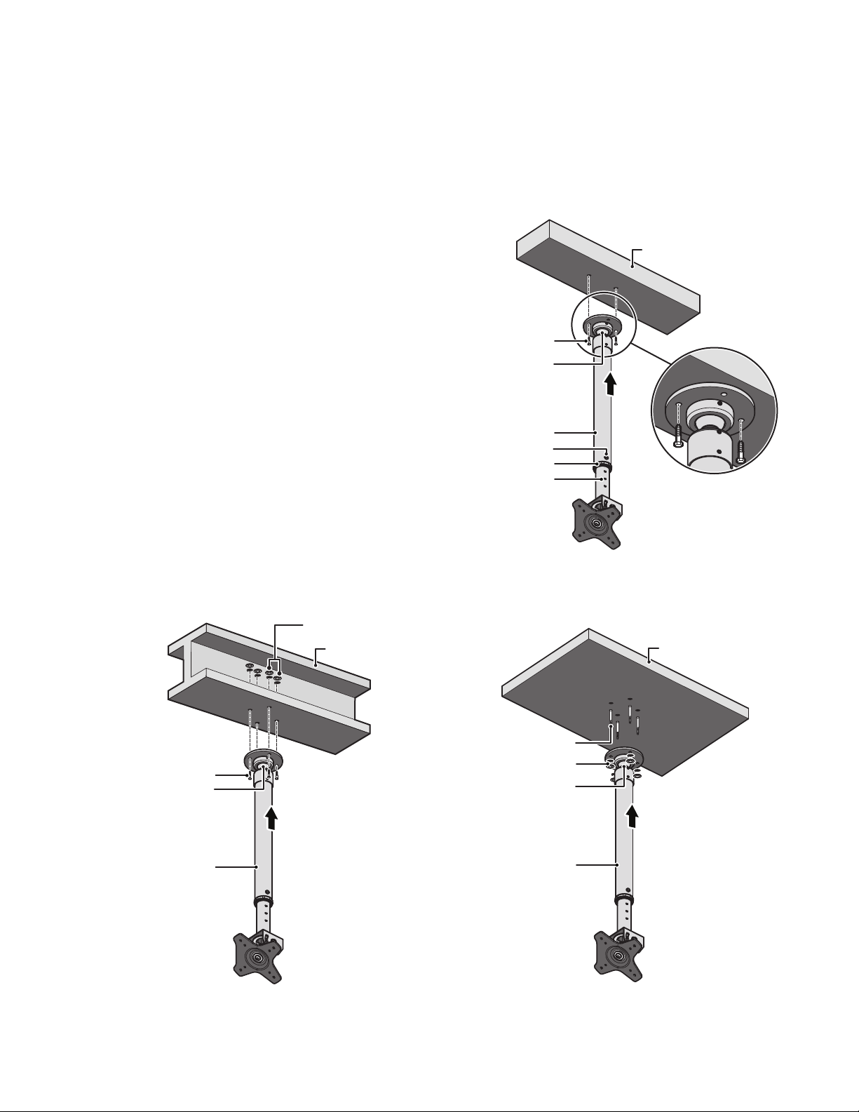
1. Attach the mounting flange to the ceiling using one of the following installation methods (mounting hardware is not supplied):
• Wood beam ceiling installation: If installing the mount to a wood ceiling stud, the stud must be at least 2-inches x 4-inches with a maximum
0.5-inch thick layer of plasterboard. For installation, the hole size should be 11/64-inch and 2-inches deep.
(1) Use a stud finder to locate and mark the edges of the stud to which
the mount will be attached.
(2) Center the mounting flange between the edges of the stud.
(3) Use the mounting flange as a template to mark two mounting holes
that are not adjacent to each other.
(4) Attach the mounting flange to the ceiling using two 1/4 x 2-inch
wood screws as shown in Figure 1.
• I-beam ceiling installation: For installation, the hole size should be
17/64-inch and deep enough to go through the flange.
(1) Use the mounting flange as a template to mark the mounting holes
on the I-beam.
(2) Attach the mounting flange to the I-beam using 1/4-20 x 1-inch
machine screws with nuts (not supplied), as shown in Figure 2.
Depending on the size of the I-beam, machine screws longer than
1- inch may be required.
• Concrete ceiling installation: The minimum concrete thickness is
3-inches. For installation, the hole size should be 1/4-inch and 1.75-inches
deep. The concrete anchor must be an ITW RED HEAD Trubolt Wedge
Anchor SWW-1422.
(1) Use the mounting flange as a template to mark the mounting holes
on the ceiling.
(2) Attach the mounting flange to the concrete ceiling using
1/4 x 1.75-inch wedge concrete anchors with nuts and washers
(not supplied), as shown in Figure 3.
WOOD SCREWS
MOUNTING FLANGE
TELESCOPING POLE
LOCKING PIN
LOCKING COLLAR
ADJUSTMENT HOLE
Figure 1. Attaching the Mount to Wood Stud Ceiling
WOOD BEAM
2. Adjust the length of the telescoping pole (refer to Figure 1 on page 2):
a. Remove the locking pin at the center of the pole using a flat head screwdriver (not supplied).
NUT/LOCK WASHER
STEEL I-BEAM
CONCRETE CEILING
b. Loosen the locking collar on the pole and slide the pole out to the desired length. Retighten the locking collar.
c. Reinsert the pin into one of the adjustment holes.
d. Tighten the locking pin screw to secure the pole.
3. Attach the telescoping pole to the mounting flange.
4. Attach the mounting head to the opposite end of the telescoping pole (refer to Figure 4).
MACHINE SCREWS
MOUNTING FLANGE
WARNING: The mount is designed to rotate at the swivel ball joint on the mounting flange. Do not rotate the mount at the joints where the
CONCRETE WEDGE ANCHOR
NUT/LOCK WASHER
MOUNTING FLANGE
pole screws into the mount.
5. Using the 3/32-inch Allen wrench (supplied), tighten the 10-32 setscrew on the mounting head and the two 10-32 setscrews on the mounting flange.
6. Using the 3/32-inch Allen wrench (supplied), loosen the 10-32 setscrew on the mounting flange ball joint.
7. Slightly loosen the retaining ring on the mounting flange. Do not completely unscrew the retaining ring.
TELESCOPING POLE
TELESCOPING POLE
8. Rotate the lower section of the mount at the ball joint until the mounting head is facing the desired direction.
9. Tighten the retaining ring and the 10-32 setscrew to lock the mount into the desired position.
10. Hold the monitor level with the mounting head and attach the monitor mount to one of the following monitors:
• 31-inch monitor or smaller: Align the monitor to the correct hole pattern on the mounting plate. Use four M4 x 10 mm Phillips pan head screws
and split lock washers (supplied) to secure the monitor to the mounting plate.
• Monitors larger than 31-inches: Align the monitor to the outside hole pattern of the monitor plate. Use four M6 x 12 mm Phillips pan head
Figure 2. Attaching the Mount to I-Beam Ceiling
Figure 3. Attaching the Mount to Concrete Ceiling
screws and flat washers (supplied) to secure the monitor to the mounting plate.
2 C2227M-G (6/15)
Page 3

2. Power and video wires can be pulled through the center of the pole or run along the outside of the pole.
3. Using the 3/16-inch Allen wrench (supplied), loosen the button head bolts on the side of the mounting head. Refer to Figure 4.
4. Tilt the monitor to the desired angle, and then retighten the button head bolts to secure the monitor in place.
5. To swivel the monitor between portrait and landscape views, loosen the nut on the back side of the mounting head using a 9/16-inch wrench (not
supplied), and then retighten the nut to secure the monitor in place.
10-32 SET SCREW
(USE A 3/32-INCH ALLEN WRENCH)
TELESCOPING POLE
MOUNTING FLANGE
10-32 SET SCREW
(USE A 3/32-INCH ALLEN WRENCH)
BUTTON HEAD BOLTS
(USE A 3/16-INCH
ALLEN WRENCH)
MOUNTING
HEAD
10-32 SET SCREW
(USE 3/32-INCH ALLEN WRENCH)
Figure 4. Mounting a Monitor using PMCL-CMP
M4 X 10MM SCREW
SPLIT LOCK WASHER
C2227M-G (6/15) 3
Page 4

WARRANTY
For information about Pelco’s product warranty and thereto related information, refer to www.pelco.com/warranty.
REVISION HISTORY
Manual # Date Comments
C2227M 8/06 Original version.
C2227M-A 11/06 Inserted statement per UL about minimum2x4wood beam.
C2227M-B 12/06 Added hardware information for large monitors per ECO 06-17078.
C2227M-C 4/07 Updated description to include PMCL-VA.
C2227M-D 8/07 Added instructions for concrete ceiling. Removed 1/16-inch Allen wrench and 6-32 setscrew. Added information about PMC-V100 adapter.
C2227M-E 6/10 Revised the model numbers in the description, reorganized the installation section, and updated the warranty and format.
C2227M-F 10/14 Added mounting details for UL compliance and updated the template.
C2227M-G 6/15 Removed references to the PMCL-VAF adapter plate.
Pelco, the Pelco logo, and other trademarks associated with Pelco products referred to in this publication are trademarks of Pelco, Inc. or its affiliates. © Copyright 2015,Pelco,Inc.
ONVIF and the ONVIF logo are trademarks of ONVIF Inc. All other product names and services are the property of their respective companies.All rights reserved.
Product specifications and availability are subject to change without notice.
Pelco, Inc. 625 W. Alluvial Ave., Fresno, CA 93711 United States
USA & Canada Tel (800) 289-9100 Fax (800) 289-9150
International Tel +1 (559) 292-1981 Fax +1 (559) 348-1120
www.pelco.com
 Loading...