

Page 1

C2227M-D (8/07)
PMCL-CMP
Monitor Mount and Telescoping Pole
Important Safety Instructions
1. Read these instructions.
2. Keep these instructions.
3. Heed all warnings.
4. Follow all instructions.
5. Installation should be done only by qualified personnel and conform to all local codes.
6. Only use installation methods and materials capable of supporting four times the maximum specified load.
7. Only use replacement parts recommended by Pelco.
8. This unit is designed for indoor use only, and it must not be installed where exposed to rain or moisture.
Description
The PMCL-CMP is a ceiling mount and pole that can be used to mount any of Pelco’s 200, 300, or 400 Series flat panel LCD monitors. This mount can also
support most sizes of Pelco’s 500 Series LCD monitors, although a PMCL-V100, PMCL-V200, or PMCL-VA adapter plate may be required. The PMCL526
monitor requires the PMCL-V100 adapter and the PMCL532 monitor requires the PMCL-V200 adapter; the adapters are included with the corresponding
monitors. The PMCL537 and PMCL542 require the PMCL-VA adapter (not included).
The PMCL-CMP mount can be swiveled 360 degrees to allow you to use your monitor in either landscape or portrait view. The mount also allows you to tilt
the monitor 35 degrees for the best viewing angle. The pole telescopes from 15 to 30 inches. This mount can also be used with Pelco’s MRCA ceiling mount.
The PMCL-CMP is capable of supporting a maximum load of 90 pounds (40.8 kg).
NOTE: If you are installing a mount using a Pelco adapter (PMCL-V100, PMCL-V200, or PMCL-VA), refer to the manual shipped with the adapter for
installation instructions.
Installation
The following parts are supplied:
Qty Description
1 Mounting flange
1 Mounting head
1 Telescoping pole
4 M4 x 10 mm pan head Phillips screws, stainless steel
4 Split lock washers
4 M6 x 12 mm pan head Phillips screws, stainless steel
4Flat washers
1 Allen wrench, 3/16-inch
1 Allen wrench, 3/32-inch
To install the ceiling mount:
NOTE: It is recommended that two people be present when mounting the monitor. One person should hold the monitor, while the second person installs the
screws to secure the monitor to the mount.
1. Attach the mounting flange to the ceiling. (Mounting hardware is not supplied.)
a. If installing the mount to a wood beam ceiling, the beam must be at least 2 inches x 4 inches with a maximum 0.5-inch thick layer of
plasterboard. Use the following steps to attach the mounting flange to a wood beam ceiling:
(1) Use a stud finder to locate and mark the edges of the wood beam that the mount will be attached to.
(2) Center the mounting flange between the edges of the beam. Use the mounting flange as a template to mark two mounting holes that are
not adjacent to each other.
(3) Attach the mounting flange to the ceiling using two 1/4 x 2-inch wood screws as shown in Figure 1 on page 2.
Page 2
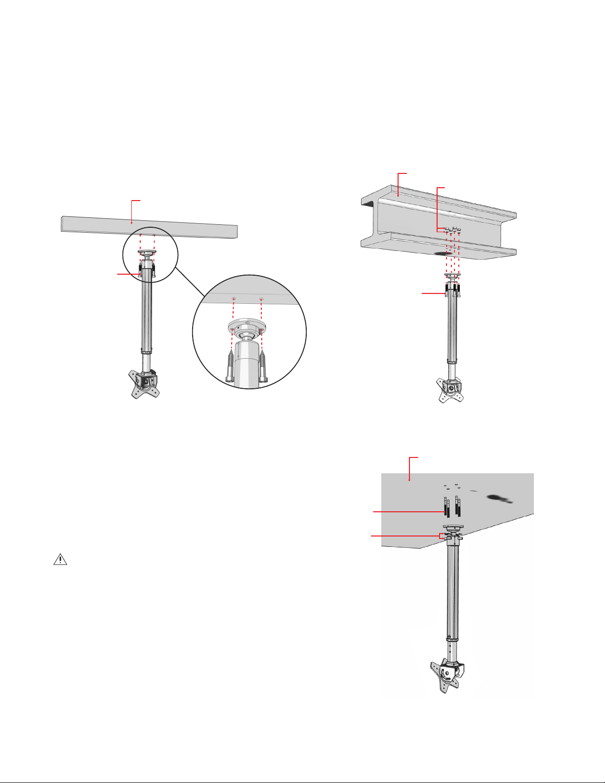
b. Use the following steps to attach the mounting flange to a steel I-beam ceiling:
(1) Use the mounting flange as a template to mark the mounting holes on the I-beam.
(2) Attach the mounting flange to the I-beam using 1/4-20 x 1-inch machine screws with nuts as shown in Figure 2. Depending on the size of
the I-beam, machine screws longer than one inch may be required.
c. Use the following steps to attach the mounting flange to a concrete ceiling:
(1) Use the mounting flange as a template to mark the mounting holes on the ceiling.
(2) Attach the mounting flange to the concrete ceiling using 1/4 x 1.75-inch wedge concrete anchors with washers and nuts. Depending on the
thickness of the ceiling, concrete anchors longer than 1.75 inches may be required.
STEEL I-BEAM
NUT/LOCK WASHER
WOOD BEAM
WOOD SCREW
MACHINE SCREWS
Figure 1. Attaching the Mount to Wood Stud Ceiling
2. Adjust the length of the telescoping pole.
a. Remove the locking pin at the center of the pole using a flat
head screwdriver (not supplied).
b. Loosen the locking collar on the pole and slide the pole out to
the desired length. Retighten the locking collar.
c. Reinsert the pin into one of the adjustment holes.
d. Tighten the locking pin screw to secure the pole.
WARNING: The mount is designed to rotate at the swivel ball
joint on the mounting flange. Do not rotate the mount at the joints
where the pole screws into the mount.
3. Secure the pipe in place by tightening the setscrews. Using the
3/32-inch Allen wrench (supplied), tighten the 10-32 setscrew on
the mounting head and the two 10-32 setscrews on the mounting
flange.
4. Using the 3/32-inch Allen wrench (supplied), loosen the
10-32 setscrew on the mounting flange ball joint. Slightly loosen
the retaining ring on the mounting flange. Do not completely
unscrew the retaining ring. Rotate the lower section of the mount
at the ball joint until the mounting head is facing the desired
direction. Tighten the retaining ring and the 10-32 setscrew to lock
the mount into the desired position.
Figure 2. Attaching the Mount to I-beam Ceiling
CONCRETE CEILING
CONCRETE WEDGE
ANCHOR
NUT/LOCK WASHER
Figure 3. Attaching the Mount to Concrete Ceiling
Page 3

5. Hold the monitor level with the mounting head. Refer to one of the following and attach the monitor mount to the monitor.
• 31-inch monitor or smaller: Align the monitor to the correct hole pattern on the mounting plate. Use the M4 x 10 mm screws and split lock
washers (supplied) to secure the monitor to the mounting plate.
• Monitors larger than 31-inches: Align the monitor to the outside hole pattern of the monitor plate. Use the M6 x 12 mm screws and flat
washers (supplied) to secure the monitor to the mounting plate.
6. Power and video wires can be pulled through the center of the pole, or run along the outside of the pole.
7. Using the 3/16-inch Allen wrench (supplied), loosen the button head bolts on the side of the mounting head. Tilt the monitor to the desired angle.
To secure the monitor in place, retighten the button head bolts.
8. To swivel the monitor between portrait and landscape views, loosen the nut on the back side of the mounting head using a 9/16-inch wrench (not
supplied). Retighten the nut to secure the monitor in place.
1/16-INCH ALLEN WRENCH)
3/32-INCH ALLEN WRENCH)
MOUNTING HEAD
BUTTON HEAD BOLTS
3/16-INCH ALLEN WRENCH
6-32 SETSCREW (USE
10-32 SETSCREW (USE
RETAINING RING
MOUNTING FLANGE
10-32 SETSCREW (USE
3/32-INCH ALLEN WRENCH)
M4 X 10 MM SCREW
SPLIT LOCK WASHER
Figure 4. Mounting a Monitor Using PMCL-CMP
The materials used in the manufacture of this document and its components are compliant to the requirements of Directive 2002/95/EC.
REVISION HISTORY
Manual # Date Comments
C2227M 8/06 Original version.
C2227M-A 11/06 Inserted statement per UL about minimum 2 x 4 wood beam.
C2227M-B 12/06 Added hardware information for large monitors per ECO 06-17078.
C2227M-C 4/07 Updated description to include PMCL-VA.
C2227M-D 8/07 Added instructions for concrete ceiling. Removed 1/16-inch Allen wrench and 6-32 setscrew. Added information about PMC-V100 adapter.
Pelco, the Pelco logo, Camclosure, Esprit, ExSite, Genex, Legacy, and Spectra are registe red trademarks of Pelco. ©Copyright 2007, Pelco. All rights reserved.
Endura, and Spectra III are trademarks of Pelco.
DLP is a registered trademark of Texas Instruments Incorporated
Page 4

PRODUCT WARRANTY AND RETURN INFORMATION
WARRANTY
Pelco will repair or replace, without charge, any merchandise proved defective in material or
workmanship for a period of one year after the date of shipment.
Exceptions to this warranty are as noted below:
• Five years on fiber optic products and TW3000 Series unshielded twisted pair transmission
products.
• Three years on Spectra
• Three years on Genex
• Three years on Camclosure
CC3701H-2X, CC3751H-2, CC3651H-2X, MC3651H-2, and MC3651H-2X camera models,
which have a five-year warranty.
• Three years on PMCL200/300/400 Series LCD monitors.
• Two years on standard motorized or fixed focal length lenses.
• Two years on Legacy
fixed dome products.
• Two years on Spectra III
continuous motion applications.
• Two years on Esprit and WW5700 Series window wiper (excluding wiper blades).
• Two years (except lamp and color wheel) on Digital Light Processing (DLP
The lamp and color wheel will be covered for a period of 90 days. The air filter is not
covered under warranty.
• Eighteen months on DX Series digital video recorders, NVR300 Series network video
recorders, and Endura
• One year (except video heads) on video cassette recorders (VCRs). Video heads will be
covered for a period of six months.
• Six months on all pan and tilts, scanners or preset lenses used in continuous motion
applications (that is, preset scan, tour and auto scan modes).
Pelco will warrant all replacement parts and repairs for 90 days from the date of Pelco
shipment. All goods requiring warranty repair shall be sent freight prepaid to Pelco, Clovis,
California. Repairs made necessary by reason of misuse, alteration, normal wear, or accident
are not covered under this warranty.
Pelco assumes no risk and shall be subject to no liability for damages or loss resulting from
the specific use or application made of the Products. Pelco’s liability for any claim, whether
based on breach of contract, negligence, infringement of any rights of any party or product liability, relating to the Products shall not exceed the price paid by the Dealer to Pelco for such
Products. In no event will Pelco be liable for any special, incidental or consequential damages
(including loss of use, loss of profit and claims of third parties) however caused, whether by
the negligence of Pelco or otherwise.
The above warranty provides the Dealer with specific legal rights. The Dealer may also have
additional rights, which are subject to variation from state to state.
®
IV products.
®
Series products (multiplexers, server, and keyboard).
®
and fixed camera models, except the CC3701H-2,
®
, CM6700/CM6800/CM9700 Series matrix, and DF5/DF8 Series
™
, Esprit®, ExSite™, and PS20 scanners, including when used in
®
) displays.
™
Series distributed network-based video products.
If a warranty repair is required, the Dealer must contact Pelco at (800) 289-9100 or
(559) 292-1981 to obtain a Repair Authorization number (RA), and provide the following
information:
1. Model and serial number
2. Date of shipment, P.O. number, Sales Order number, or Pelco invoice number
3. Details of the defect or problem
If there is a dispute regarding the warranty of a product which does not fall under the
warranty conditions stated above, please include a written explanation with the product when
returned.
Method of return shipment shall be the same or equal to the method by which the item was
received by Pelco.
RETURNS
In order to expedite parts returned to the factory for repair or credit, please call the factory at
(800) 289-9100 or (559) 292-1981 to obtain an authorization number (CA number if returned for
credit, and RA number if returned for repair).
All merchandise returned for credit may be subject to a 20% restocking and refurbishing
charge.
Goods returned for repair or credit should be clearly identified with the assigned CA or RA
number and freight should be prepaid. Ship to the appropriate address below.
If you are located within the continental U.S., Alaska, Hawaii or Puerto Rico, send goods to:
Service Department
Pelco
3500 Pelco Way
Clovis, CA 93612-5699
If you are located outside the continental U.S., Alaska, Hawaii or Puerto Rico and are instructed
to return goods to the USA, you may do one of the following:
If the goods are to be sent by a COURIER SERVICE, send the goods to:
Pelco
3500 Pelco Way
Clovis, CA 93612-5699 USA
If the goods are to be sent by a FREIGHT FORWARDER, send the goods to:
Pelco c/o Expeditors
473 Eccles Avenue
South San Francisco, CA 94080 USA
Phone: 650-737-1700
Fax: 650-737-0933
Worldwide Headquarters
3500 Pelco Way
Clovis, California 93612 USA
USA & Canada
Tel: 800/289-9100
Fax: 800/289-9150
International
Tel: 1-559/292-1981
Fax: 1-559/348-1120
www.pelco.com
ISO9001
Australia|Canada|Finland|France|Germany|Italy|Macau|The Netherlands|Russia|Singapore
South Africa
Spain|Sweden|United Arab Emirates|United Kingdom|United States
|
 Loading...