

Page 1
INSTALLATION/OPERATION
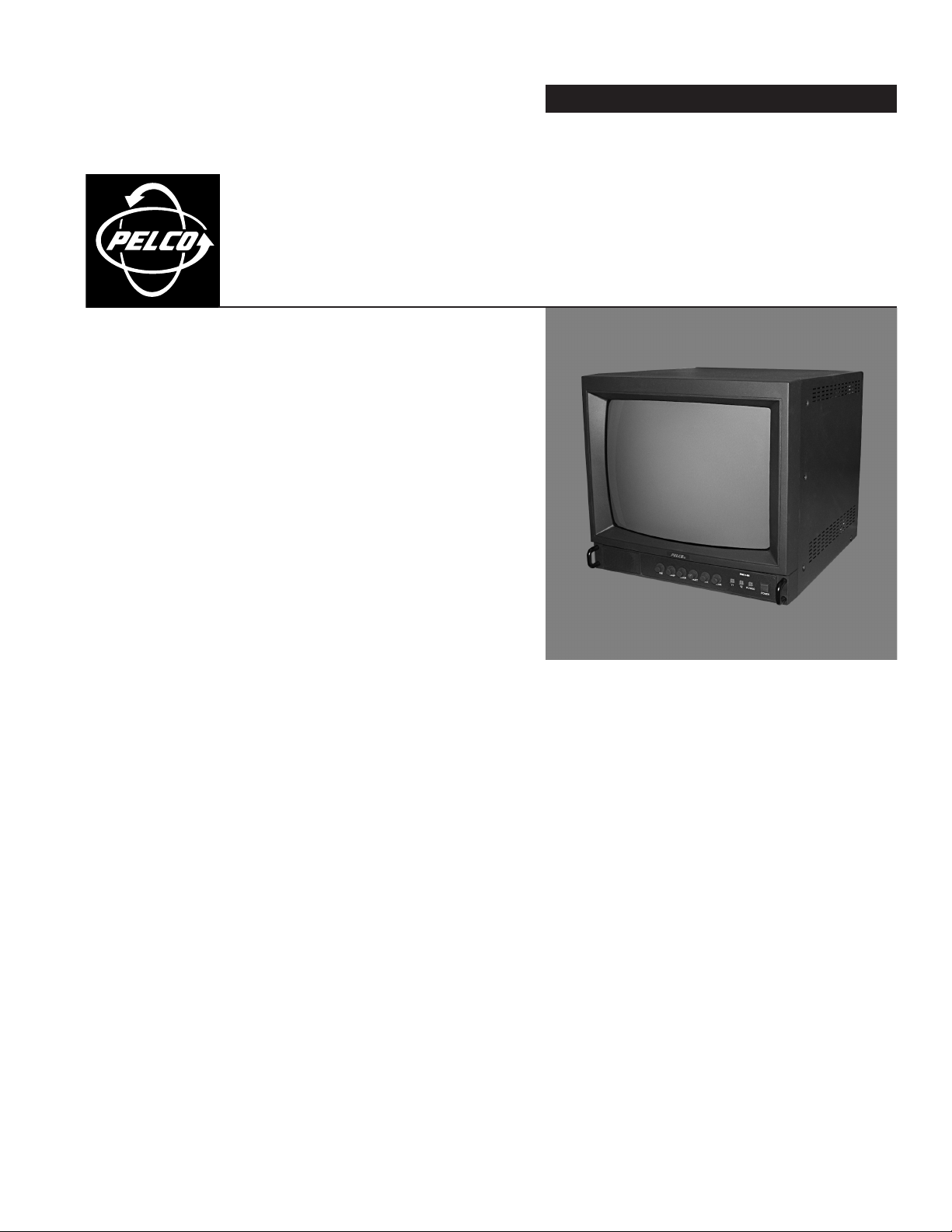
PMC14H and PMC14H-GY
®
14-Inch Color Monitor
C2906M (7/03)
Page 2

IMPORTANT SAFEGUARDS AND WARNINGS
1. Read these instructions.
2. Keep these instructions.
3. Heed all warnings.
4. Follow all instructions.
5. Do not use this monitor near water.
6. Do not block any ventilation openings. Install in accordance with the manufacturer’s instructions.
7. Do not install near any heat sources such as radiators, heat registers, stoves, or other apparatus (including amplifiers)
that produce heat.
8. Do not defeat the safety purpose of the polarized or grounding-type plug. A polarized plug has two blades with one wider
than the other. A grounding plug has two blades and a third grounding prong. The wide blade or the third prong is
provided for your safety. If the provided plug does not fit into your outlet, consult your electrician for replacement of the
obsolete outlet.
9. Protect the power cord from being walked on or pinched, particularly at the plug, convenience receptacle, and the point
where it exits from the apparatus.
10. Unplug the monitor during lightning storms or when unused for long periods of time.
11. Refer all servicing to qualified service personnel. Servicing is required when the monitor has been damaged in any way,
such as when the power supply cord or plug is damaged, liquid has been spilled or objects have fallen into the monitor,
the monitor has been exposed to rain or moisture, the monitor does not operate normally, or the monitor has been
dropped.
12. The monitor shall not be exposed to dripping or splashing, and no objects filled with liquids, such as vases, shall be
placed on the monitor.
13. Warning: To reduce the risk of fire or electric shock, do not expose this monitor to rain or moisture.
DESCRIPTION
REGULATORY NOTICES
14. A CCC-approved power cord must be used to power this equipment when used in China.
This device complies with part 15 of the FCC Rules. Operation is subject to the following two conditions: (1) this device may not
cause harmful interference, and (2) this device must accept any interference received, including interference that may cause
undesired operation.
RADIO AND TELEVISION INTERFERENCE
This equipment has been tested and found to comply with the limits of a Class A digital device, pursuant to Part 15 of the FCC
Rules. These limits are designed to provide reasonable protection against harmful interference when the equipment is
operated in a commercial environment. This equipment generates, uses, and can radiate radio frequency energy and, if not
installed and used in accordance with the instruction manual, may cause harmful interference to radio communications.
Operation of this equipment in a residential area is likely to cause harmful interference in which case the user will be required
to correct the interference at his own expense.
Changes and modifications not expressly approved by the manufacturer or registrant of this equipment can void your authority
to operate this equipment under Federal Communications Commission’s rules.
This Class A digital apparatus complies with Canadian ICES-003.
Cet appareil numérique de la classe A est conforme à la norme NMB-003 du Canada.
2 C2906M (7/03)
Page 3

DESCRIPTION
The PMC14H is a high-resolution color monitor that can be used in desktop applications or rack mounted using the optional
RMA14F rack mount kit. The monitor supports NTSC and PAL video, as well as 120 VAC and 230 VAC input power. An
automatic switching system makes all the necessary changes for adapting to the required formats. Manual selection is not
required. A separate power cord is supplied for each voltage input.
The back panel of the PMC14H has two BNC video inputs with looping outputs, one S-Video input, and multiple audio inputs
and outputs. All image adjustment controls are conveniently located on the front panel of the monitor.
C2906M (7/03) 3
Page 4

INSTALLATION
1. Make all equipment connections as required for your
installation. Refer to Figures 1 through 3 for samples of
installation methods.
Refer to Table A for coaxial cable requirements.
2. Plug power cord into the AC INLET connection on the
rear panel of the monitor. Plug the other end into a
power receptacle.
CAMERA
IN
CAMERA
OUT
Table A. Video Coaxial Cable Requirements
Cable Type* Maximum Distance
RG59/U 750 ft (229 m)
RG6/U 1,000 ft (305 m)
RG11/U 1,500 ft (457 m)
*Minimum cable requirements:
75 ohms impedance
All-copper center conductor
All-copper braided shield with 95% braid coverage
VIDEO
V1
V2
S-VIDEO
AUDIO
V1 V2 S-VIDEO
IN
OU
T
VCR
VCR
Figure 1. Looping Operation – One Monitor with External Video Equipment
4 C2906M (7/03)
Page 5

IN
VIDEO
V1 V2
AUDIO
V1 V2 S-VIDEO
IN
CAMERA
OUT
S-VIDEO
OUT
S-VHS OUT AUDIO OUT
Figure 2. S-VHS Video Input Connections
Note: The S-Video connector is an input connector; there is no loop-through capability using S-Video.
VIDEO
V1 V2
IN
CAMERA
OUT
S-VIDEO
AUDIO
V1 V2 S-VIDEO
VCR
IN
OUT
VIDEO
V1 V2
IN
OUT
S-VIDEO
VIDEO
V1 V2
IN
OUT
S-VIDEO
AUDIO
V1 V2 S-VIDEO
IN
OUT
AUDIO
V1 V2 S-VIDEO
IN
OUT
VCR
Figure 3. Looping Operation – Maximum of Three Monitors with External Video Equipment
C2906M (7/03) 5
Page 6

OPERATION
1. Press the POWER button to turn the monitor on. The LED above the power button will illuminate when the monitor is on.
2. Select the camera by pressing the V1, V2, or S-VIDEO button (refer to Figure 4).
3. If required adjust the picture using the control knobs on the front panel. Refer to Figure 4 for front panel controls.
FRONT PANEL ADJUSTMENTS
TINT Color phase adjustment. Turn clockwise to increase the greenish tones in the picture. Turn counterclockwise
to increase the reddish tones in the picture.
COLOR Color saturation level. Turn the control knob clockwise to increase the saturation level and counterclockwise
to decrease the saturation level.
CONT Contrast adjustment. Proper adjustment will allow maximum gradations between the darkest and lightest
picture contrast. Turn the control clockwise to increase picture contrast and counterclockwise to decrease
contrast.
BRIGHT Brightness display adjustment. Turn the control clockwise to increase brightness and counterclockwise to
decrease brightness.
SHARP Sharpness adjustment. Adjust control knob to obtain the clearest picture.
VOLUME Audio adjustment. Turn the control clockwise to increase volume and counterclockwise to decrease volume.
TINT SHARP COLOR BRIGHT CONT. VOLUME
Figure 4. Front Panel of Monitor
PMC14H
V1 V2 S-VIDEO
POWER
6 C2906M (7/03)
Page 7

SPECIFICATIONS
ELECTRICAL
Input Voltage: 100-240 VAC, 50/60 Hz, automatic switching
Power Consumption: 45 watts
Horizontal Resolution: 450 TV lines, center of screen
Visual Picture Size: 14-inch (35.56 cm) diagonal
Sweep Linearity: 10%
Speaker Output: 1.0 watt (-3 dBV)
GENERAL
Input/Output
Video: 2 BNC inputs, 75 ohms or Hi-Z
Audio: 3 RCA inputs, Hi-Z
S-Video: 1 DIN input
Construction: Steel cabinet
Finish
PMC14H: Black
PMC14H-GY Gray
Dimensions: 13.76 (W) x 12.89 (H) x 14.59 (D) inches
Weight: 30.6 lb (14 kg)
ENVIRONMENTAL
Operating Temperature: 32° to 106°F (0° to 41°C)
Humidity: 10% to 85% (non-condensing)
2 looping outputs
3 looping outputs
(34.8 x 32.7 x 37.0 cm)
(Design and product specifications subject to change without notice.)
REVISION HISTORY
Manual # Date Comments
C2906M 7/03 Original version.
® Pelco and the Pelco logo are registered trademarks of Pelco. © Copyright 2003, Pelco. All rights reserved.
C2906M (7/03) 7
Page 8

WARRANTY AND RETURN INFORMATION
WARRANTY
Pelco will repair or replace, without charge, any merchandise proved defective in material or
workmanship for a period of one year after the date of shipment. Exceptions to this warranty are
as noted below:
• Five years on Pelco manufactured cameras (CC3500/CC3600/CC3700 and MC3500/
MC3600 Series); two years on all other cameras.
• Three years on Genex® Series (multiplexers, server, and keyboard) and 090 Series
Camclosure® Camera System.
• Two years on 100/150, 200 and 300 Series Camclosure® Camera Systems.
• Two years on all standard motorized or fixed focal length lenses.
• Two years on Legacy®, CM6700/CM6800/CM8500/CM9500/CM9740/CM9760 Matrix, DF5
and DF8 Series Fixed Dome products.
• Two years on Spectra®, Esprit®, and PS20 Scanners, including when used in continuous
motion applications.
• Two years on Esprit and WW5700 series window wiper (excluding wiper blades).
• Eighteen months on DX Series digital video recorders.
• One year (except video heads) on video cassette recorders (VCRs). Video heads will be
covered for a period of six months.
• Six months on all pan and tilts, scanners or preset lenses used in continuous motion
applications (that is, preset scan, tour and auto scan modes).
Pelco will warrant all replacement parts and repairs for 90 days from the date of Pelco
shipment. All goods requiring warranty repair shall be sent freight prepaid to Pelco, Clovis,
California. Repairs made necessary by reason of misuse, alteration, normal wear, or accident
are not covered under this warranty.
Pelco assumes no risk and shall be subject to no liability for damages or loss resulting from the
specific use or application made of the Products. Pelco’s liability for any claim, whether based on
breach of contract, negligence, infringement of any rights of any party or product liability, relating
to the Products shall not exceed the price paid by the Dealer to Pelco for such Products. In no
event will Pelco be liable for any special, incidental or consequential damages (including loss of
use, loss of profit and claims of third parties) however caused, whether by the negligence of
Pelco or otherwise.
The above warranty provides the Dealer with specific legal rights. The Dealer may also have
additional rights, which are subject to variation from state to state.
If a warranty repair is required, the Dealer must contact Pelco at (800) 289-9100 or (559) 292-1981 to
obtain a Repair Authorization number (RA), and provide the following information:
1. Model and serial number
2. Date of shipment, P.O. number, Sales Order number, or Pelco invoice number
3. Details of the defect or problem
If there is a dispute regarding the warranty of a product which does not fall under the warranty conditions
stated above, please include a written explanation with the product when returned.
Method of return shipment shall be the same or equal to the method by which the item was received by
Pelco.
RETURNS
In order to expedite parts returned to the factory for repair or credit, please call the factory at (800) 289-9100
or (559) 292-1981 to obtain an authorization number (CA number if returned for credit, and RA number if
returned for repair).
All merchandise returned for credit may be subject to a 20% restocking and refurbishing charge.
Goods returned for repair or credit should be clearly identified with the assigned CA or RA number and
freight should be prepaid. Ship to the appropriate address below.
If you are located within the continental U.S., Alaska, Hawaii or Puerto Rico:
Service Department
Pelco
3500 Pelco Way
Clovis, CA 93612-5699
If you are located outside the continental U.S., Alaska, Hawaii or Puerto Rico:
Intermediate Consignee Ultimate Consignee
American Overseas Air Freight Pelco
320 Beach Road 3500 Pelco Way
Burlingame, CA 94010 Clovis, CA 93612-5699
USA USA
This equipment contains electrical or electronic components that must be recycled properly to comply with Directive 2002/
96/EC of the European Union regarding the disposal of waste electrical and electronic equipment (WEEE). Contact your
local dealer for procedures for recycling this equipment.
World Headquarters
3500 Pelco Way
Clovis, California 93612 USA
USA & Canada
Tel: 800/289-9100
Fax: 800/289-9150
International
Tel: 1-559/292-1981
Fax: 1-559/348-1120
www.pelco.com
ISO9001
Orangeburg, New York Las Vegas, Nevada Eindhoven, The Netherlands Wokingham, United Kingdom Montreal, Canada
 Loading...