


INSTALLATION
INSTALLATION
ExSite™ Series Mounts
WXM100, CMXM100, PAXM100,
PXM200, and AXM100 Models
C2216M (5/05)


Important Safety Instructions
CAUTION:
RISK OF ELECTRIC
SHOCK.
1. Read these instructions.
2. Keep these instructions.
3. Heed all warnings.
4. Follow all instructions.
5. Only use attachments/accessories specified by the manufacturer.
6. Use only with the cart, stand, tripod, bracket, or table specified by the manufacturer, or sold with the apparatus. When a cart is used, use caution when moving the cart/apparatus combination to avoid injury from tip-over.
7. Installation should be done only by qualified personnel and conform to all local codes.
8. Use only installation methods and materials capable of supporting four times the maximum specified load.
9. Use stainless steel hardware to fasten the mount to outdoor surfaces.
CAUTION: These servicing instructions are for use by qualified service personnel only. To reduce the risk of electric shock do not perform any
servicing other that contained in the operating instructions unless you are qualified to do so.
10. Only use replacement parts recommended by Pelco.
The product and/or manual may bear the following marks:
WARNING: This symbol indicates that dangerous voltage constituting a
risk of electric shock is present within this unit.
This symbol indicates that there are important operating and maintenance
instructions in the literature accompanying this unit.
3 C2216M (5/05)

Description
This manual contains the installation instructions for the following ExSite™ Series mounts:
WXM100 Wall mount designed to mount the ExSite
CMXM100 Corner adapter for use with the WXM100 to mount an ExSite Series system to the corner of a structure.
PAXM100 Pole adapter for use with the WXM100 to mount a system to a horizontal pole.
PXM200 Pedestal mount designed to mount an ExSite Enhanced Series system directly to a horizontal surface in either an upright or
AXM100 Adjustable mount for ExSite Enhanced Fixed models allowing manual pan/tilt adjustment..
inverted position
Series system directly to a load-bearing vertical surface.
Model Supplied Hardware
WXM100 /
PXM200
CMXM100
PAXM100
AXM100
None
Five 3/8-16 x 1.0-inch
thread length,
stainless steel hex
head bolts with lock
washers to attach the
adapter to the
WXM100 wall mount
Four 5/8-inch wide x
40-inch (101.6 cm) long
stainless steel straps
to attach the adapter
to a pole
Five 3/8-16 x 1.0-inch
thread length,
stainless steel hex
head bolts with lock
washers to attach the
adapter to the
WXM100 wall mount
Mounting
Surface
Solid Concrete*
Steel I Beam**
Solid Concrete*
Steel I Beam**
Steel pole with a
diameter between
4 and 9 inches
(10.16 to 22.86 cm)
Recommended Hardware
Five 3/8-16 x 1-9/16-inch long stainless steel drop-in anchors and five 3/8-16 x
1.0-inch thread length, stainless steel hex head bolts with stainless steel lock washers
Five 3/8-16 x 1.0-inch thread length, stainless steel hex head bolts with stainless
steel lock washers and 3/8-16 stainless steel nuts
Six 1/2-13 x 2-inch stainless steel drop-in anchors and six 1/2-13 x 1.0-inch thread
length, stainless steel hex head bolts with stainless steel lock washers
Six 1/2-13 x 1.0-inch thread length, stainless steel hex head bolts with stainless
steel lock washers and 1/2-13 stainless steel nuts
Supplied
*Recommended strength of concrete is 3,600 psi or 25 Mpa.
**Minimum of 1/8-inch wall.
C2216M (5/05) 4
Installation
WXM100 WALL MOUNT
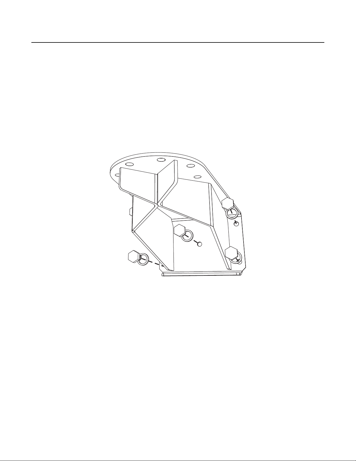
To install the WXM100 refer to Figure 1 and perform the following steps:
1. Determine the mounting location. The mounting surface should be able to support four times the combined weight of the mount and ExSite system.
2. Using the flanged end of the wall mount as a template, mark the five fastener hole positions onto the mounting surface. Set the WXM100 mount to the side and prepare the holes for the fasteners.
3. Position the wall mount over the mounting holes. Attach the mount to the mounting surface with the appropriate hardware (not supplied).
4. Secure the ExSite power module to the WXM100 with the 8 mm Allen wrench and four M10 x 16 mm stainless steel bolts supplied with the power module. Tighten the bolts to 25 to 27 ft-lb (34 to 37 Nm).
5. Complete the ExSite system installation following the instructions supplied with the equipment.
Figure 1. WXM100 Installation
5 C2216M (5/05)

CMXM100 CORNER MOUNT ADAPTER
To install the CMXM100 refer to Figure 2 and perform the following steps:
1. Attach the corner mount adapter to the mounting surface with the appropriate hardware (not supplied). The mounting surface should be able to support four times the combined weight of the corner mount adapter, WXM100 mount, and ExSite system.
2. Attach the WXM100 wall mount to the corner mount adapter with the supplied five 3/8-16 x 1.0-inch thread length, stainless steel hex head bolts and stainless steel lock washers.
3. Secure the ExSite power module to the WXM100 with the 8 mm Allen wrench and four M10 x 16 mm stainless steel bolts supplied with the power module. Tighten the bolts to 25 to 27 ft-lb (34 to 37 Nm).
4. Complete the ExSite system installation following the instructions supplied with the equipment.
Figure 2. CMXM100 Installation
C2216M (5/05) 6

PAXM100 POLE MOUNT ADAPTER
Install the PAXM100 to a steel pole with a diameter between 4 and 9 inches (10.16 to 22.86 cm). Refer to Figure 3 and perform the following
steps:
1. Attach the pole mount adapter to the pole with the four stainless steel straps (supplied). Tighten the clamps of the straps to 6.25 to
7.5 ft-lb (8.5 to 10.2 Nm).
2. Attach the WXM100 wall mount to the pole mount adapter with the supplied five 3/8-16 x 1.0-inch thread length, stainless steel hex head bolts and stainless steel lock washers.
3. Secure the ExSite power module to the WXM100 with the 8 mm Allen wrench and four M10 x 16 mm stainless steel bolts supplied with the power module. Tighten the bolts to 25 to 27 ft-lb (34 to 37 Nm).
4. Complete the ExSite system installation following the instructions supplied with the equipment.
Figure 3. PAXM100 Installation
7 C2216M (5/05)
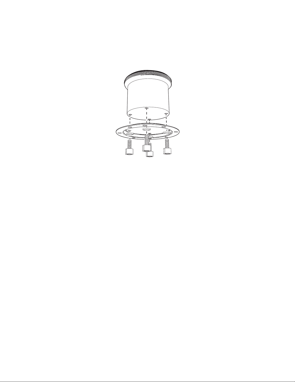
PXM200 PEDESTAL MOUNT
The PXM200 mount is designed to make the installation and removal of the ExSite power module quick and easy.
1. Secure the camera to the mounting surface with the four M10 x 16 mm stainless steel bolts and lock washers (supplied).
2. Using the 8 mm Allen wrench, tighten the bolts to 25 to 27 ft-lb (34 to 37 N-m).
The figure below shows the power module section of the camera being installed on a pedestal mount.
Figure 4. Attach the Camera to the Mounting Surface
3. Complete the ExSite system installation following the instructions supplied with the equipment.
C2216M (5/05) 8

AXM100 MANUAL TILT MOUNT
1. Attach the mount to the mounting surface.
2. Attach the camera to the mounting surface. Use only installation methods and materials capable of supporting four times the maximum specified load of the system.
3. Secure the camera to the mounting surface with the four M10 x 16 mm stainless steel bolts and lock washers (supplied). Make sure the
threads on the underside of the camera and the threads of the four M10 x 16 mm stainless steel bolts (supplied) are free of dirt and debris.
4. Using the 8 mm Allen wrench, tighten the bolts to 25 to 27 ft-lb (34 to 37 N-m).
9 C2216M (5/05)
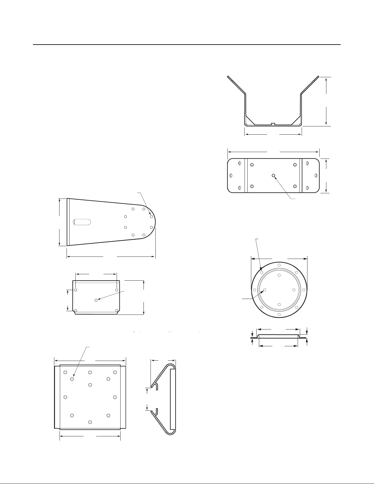
Specifications
CMXM100
10.00
(25.4)
4X 0.500 THRU EQ SP
ON A 7.25 B.C.
Ø
3.5
8.50
(21.6)
PAXM100
NOTE: VALUES IN PARENTHESES ARE CENTIMETERS;
ALL OTHERS ARE INCHES.
3.28
(8.33)
3.5
(8.9)
8.50
(21.6)
PXM100
THRU EQ SP ON A Ø 8.00 B.C.
T
22.85
(9.00)
17.78
(Ø7.00)
16.18
(Ø6.37)
1.66
0.25
5X Ø 0.422
7.00
(17.78)
3.50
(8.89)
8.00
(20.32)
14.95
(37.97)
8X 0.433 THRU EQ SP
ON A 4.75 B.C.
Ø
5.74
(14.58)
Construction
Mounts Electro-polished 304 stainless steel
PAXM100 Mounting Straps 316 stainless steel
Maximum Load
WXM100 73 lb (33 kg)
CMXM100 85 lb (38.50 kg)
PAXM100 88 lb (40 kg)
PXM200 79 lb (35.83 kg)
Weight
WXM100 12.4 lb (5.62 kg)
CMXM100 7.6 lb (3.45 kg)
PAXM100 9.2 lb (4.17 kg)
PXM200 1.3 lb (0.60 kg)
WXM100
9.25
(23.5)
14.9
(37.8)
8.15
(20.7)
5.5
(14.1)
5X THREADED HOLES
Ø
FOR 3/8-16 SS BOLTS
8X Ø 0.433 INCHES
4X Ø 0.433 INCHES
HRU EQ SP ON A
Ø 4.75 B.C
(0.65)
(0.098)
C2216M (5/05) 10

WARRANTY STATEMENT
For information about Pelco’s product warranty and thereto related information, refer to www.pelco.com/warranty.
This equipment contains electrical or electronic components that must be recycled properly to comply with Directive 2002/96/EC of the European Union
regarding the disposal of waste electrical and electronic equipment (WEEE). Contact your local dealer for procedures for recycling this equipment.
REVISION HISTORY
Manual # Date Comments
CxxxxM 4/17 Original version.
Pelco, the Pelco logo, and other trademarks associa ted with Pelco products referred to in this publication are trademarks of Pelco, Inc. or its affilia tes. © Copyright 2015, Pelco, Inc.
ONVIF and the ONVIF logo are trademarks of ONVIF Inc. All other product names and services are the property of their respective companies. All rights reserved.
Product specifications and availability are subject to change without notice.

Pelco, Inc. 625 W. Alluvial Ave., Fresno, CA 93711 United States
USA & Canada Tel (800) 289-9100 Fax (800) 289-9150
International Tel +1 (559) 292-1981 Fax +1 (559) 348-1120
www.pelco.com
 Loading...