

Page 1

INSTALLATION
Endura® NET5400T Series Video Encoder
C4658M-D (12/12)
Page 2

Contents
Important Notices . . . . . . . . . . . . . . . . . . . . . . . . . . . . . . . . . . . . . . . . . . . . . . . . . . . . . . . . . . . . . . . . . . . . . . . . . . . . . . . . . . . 6
Legal Notice. . . . . . . . . . . . . . . . . . . . . . . . . . . . . . . . . . . . . . . . . . . . . . . . . . . . . . . . . . . . . . . . . . . . . . . . . . . . . . . . . . . 6
Regulatory Notices . . . . . . . . . . . . . . . . . . . . . . . . . . . . . . . . . . . . . . . . . . . . . . . . . . . . . . . . . . . . . . . . . . . . . . . . . . . . . 6
Video Quality Caution . . . . . . . . . . . . . . . . . . . . . . . . . . . . . . . . . . . . . . . . . . . . . . . . . . . . . . . . . . . . . . . . . . . . . . . . . . . . . . . . 7
Description . . . . . . . . . . . . . . . . . . . . . . . . . . . . . . . . . . . . . . . . . . . . . . . . . . . . . . . . . . . . . . . . . . . . . . . . . . . . . . . . . . . . . . . . 8
Features . . . . . . . . . . . . . . . . . . . . . . . . . . . . . . . . . . . . . . . . . . . . . . . . . . . . . . . . . . . . . . . . . . . . . . . . . . . . . . . . . . . . . . 9
Models . . . . . . . . . . . . . . . . . . . . . . . . . . . . . . . . . . . . . . . . . . . . . . . . . . . . . . . . . . . . . . . . . . . . . . . . . . . . . . . . . . . . . . . 9
Supplied Accessories. . . . . . . . . . . . . . . . . . . . . . . . . . . . . . . . . . . . . . . . . . . . . . . . . . . . . . . . . . . . . . . . . . . . . . . . . . . . 9
Optional Accessories . . . . . . . . . . . . . . . . . . . . . . . . . . . . . . . . . . . . . . . . . . . . . . . . . . . . . . . . . . . . . . . . . . . . . . . . . . . . 9
Before You Begin . . . . . . . . . . . . . . . . . . . . . . . . . . . . . . . . . . . . . . . . . . . . . . . . . . . . . . . . . . . . . . . . . . . . . . . . . . . . . . . . . . 10
User-Supplied Parts . . . . . . . . . . . . . . . . . . . . . . . . . . . . . . . . . . . . . . . . . . . . . . . . . . . . . . . . . . . . . . . . . . . . . . . . . . . . 10
Package Contents . . . . . . . . . . . . . . . . . . . . . . . . . . . . . . . . . . . . . . . . . . . . . . . . . . . . . . . . . . . . . . . . . . . . . . . . . . . . . 11
Product Serial Number Label Placement. . . . . . . . . . . . . . . . . . . . . . . . . . . . . . . . . . . . . . . . . . . . . . . . . . . . . . . . . . . . 12
Equipment Placement and Rack Mounting. . . . . . . . . . . . . . . . . . . . . . . . . . . . . . . . . . . . . . . . . . . . . . . . . . . . . . . . . . . . . . . 13
Desktop Installation. . . . . . . . . . . . . . . . . . . . . . . . . . . . . . . . . . . . . . . . . . . . . . . . . . . . . . . . . . . . . . . . . . . . . . . . . . . . 13
Wall Mounting. . . . . . . . . . . . . . . . . . . . . . . . . . . . . . . . . . . . . . . . . . . . . . . . . . . . . . . . . . . . . . . . . . . . . . . . . . . . . . . . 14
Rack Mounting. . . . . . . . . . . . . . . . . . . . . . . . . . . . . . . . . . . . . . . . . . . . . . . . . . . . . . . . . . . . . . . . . . . . . . . . . . . . . . . . 15
Pelco Badge Orientation . . . . . . . . . . . . . . . . . . . . . . . . . . . . . . . . . . . . . . . . . . . . . . . . . . . . . . . . . . . . . . . . . . . . . . . . 17
Connections . . . . . . . . . . . . . . . . . . . . . . . . . . . . . . . . . . . . . . . . . . . . . . . . . . . . . . . . . . . . . . . . . . . . . . . . . . . . . . . . . . . . . . 18
4-Channel Models . . . . . . . . . . . . . . . . . . . . . . . . . . . . . . . . . . . . . . . . . . . . . . . . . . . . . . . . . . . . . . . . . . . . . . . . . . . . . 18
2-Channel Models . . . . . . . . . . . . . . . . . . . . . . . . . . . . . . . . . . . . . . . . . . . . . . . . . . . . . . . . . . . . . . . . . . . . . . . . . . . . . 19
1-Channel Models . . . . . . . . . . . . . . . . . . . . . . . . . . . . . . . . . . . . . . . . . . . . . . . . . . . . . . . . . . . . . . . . . . . . . . . . . . . . . 20
Connecting Video Input and Output Devices. . . . . . . . . . . . . . . . . . . . . . . . . . . . . . . . . . . . . . . . . . . . . . . . . . . . . . . . . 21
Connecting Audio. . . . . . . . . . . . . . . . . . . . . . . . . . . . . . . . . . . . . . . . . . . . . . . . . . . . . . . . . . . . . . . . . . . . . . . . . . . . . . 23
Connecting a PTZ Device, Relay, and Alarms . . . . . . . . . . . . . . . . . . . . . . . . . . . . . . . . . . . . . . . . . . . . . . . . . . . . . . . . 24
Connecting to the Network . . . . . . . . . . . . . . . . . . . . . . . . . . . . . . . . . . . . . . . . . . . . . . . . . . . . . . . . . . . . . . . . . . . . . . 31
Connecting Power . . . . . . . . . . . . . . . . . . . . . . . . . . . . . . . . . . . . . . . . . . . . . . . . . . . . . . . . . . . . . . . . . . . . . . . . . . . . . 33
Front Panel Indicators . . . . . . . . . . . . . . . . . . . . . . . . . . . . . . . . . . . . . . . . . . . . . . . . . . . . . . . . . . . . . . . . . . . . . . . . . . 35
Descriptions of the Front Panel Indicators . . . . . . . . . . . . . . . . . . . . . . . . . . . . . . . . . . . . . . . . . . . . . . . . . . . . . . . . . . 37
Connecting Video Input. . . . . . . . . . . . . . . . . . . . . . . . . . . . . . . . . . . . . . . . . . . . . . . . . . . . . . . . . . . . . . . . . . . . . 22
Connecting Looping Video . . . . . . . . . . . . . . . . . . . . . . . . . . . . . . . . . . . . . . . . . . . . . . . . . . . . . . . . . . . . . . . . . . 22
Connecting a PTZ Device (Pelco D) . . . . . . . . . . . . . . . . . . . . . . . . . . . . . . . . . . . . . . . . . . . . . . . . . . . . . . . . . . . . 25
Connecting a Relay Device . . . . . . . . . . . . . . . . . . . . . . . . . . . . . . . . . . . . . . . . . . . . . . . . . . . . . . . . . . . . . . . . . . 27
Connecting Alarms . . . . . . . . . . . . . . . . . . . . . . . . . . . . . . . . . . . . . . . . . . . . . . . . . . . . . . . . . . . . . . . . . . . . . . . . 28
Daisy-Chaining Several Units . . . . . . . . . . . . . . . . . . . . . . . . . . . . . . . . . . . . . . . . . . . . . . . . . . . . . . . . . . . . . . . . 32
Power Consumption . . . . . . . . . . . . . . . . . . . . . . . . . . . . . . . . . . . . . . . . . . . . . . . . . . . . . . . . . . . . . . . . . . . . . . . 34
Recommended Wire Gauge and Wiring Distances . . . . . . . . . . . . . . . . . . . . . . . . . . . . . . . . . . . . . . . . . . . . . . . 34
4-Channel Models. . . . . . . . . . . . . . . . . . . . . . . . . . . . . . . . . . . . . . . . . . . . . . . . . . . . . . . . . . . . . . . . . . . . . . . . . 35
2-Channel Models. . . . . . . . . . . . . . . . . . . . . . . . . . . . . . . . . . . . . . . . . . . . . . . . . . . . . . . . . . . . . . . . . . . . . . . . . 36
1-Channel Models. . . . . . . . . . . . . . . . . . . . . . . . . . . . . . . . . . . . . . . . . . . . . . . . . . . . . . . . . . . . . . . . . . . . . . . . . 36
2 C4658M-D (12/12)
Page 3

Troubleshooting . . . . . . . . . . . . . . . . . . . . . . . . . . . . . . . . . . . . . . . . . . . . . . . . . . . . . . . . . . . . . . . . . . . . . . . . . . . . . . . . . . . 38
Specifications . . . . . . . . . . . . . . . . . . . . . . . . . . . . . . . . . . . . . . . . . . . . . . . . . . . . . . . . . . . . . . . . . . . . . . . . . . . . . . . . . . . . . 40
C4658M-D (12/12) 3
Page 4

List Of Illustrations
1 Package Contents . . . . . . . . . . . . . . . . . . . . . . . . . . . . . . . . . . . . . . . . . . . . . . . . . . . . . . . . . . . . . . . . . . . . . . . . . . . . . 11
2 Product Serial Number Label Placement. . . . . . . . . . . . . . . . . . . . . . . . . . . . . . . . . . . . . . . . . . . . . . . . . . . . . . . . . . . . 12
3 Attaching Rubber Feet for Desktop Placement . . . . . . . . . . . . . . . . . . . . . . . . . . . . . . . . . . . . . . . . . . . . . . . . . . . . . . . 13
4 Desktop Placement . . . . . . . . . . . . . . . . . . . . . . . . . . . . . . . . . . . . . . . . . . . . . . . . . . . . . . . . . . . . . . . . . . . . . . . . . . . . 14
5 NET5400T and WS5200-4U Wall Mount . . . . . . . . . . . . . . . . . . . . . . . . . . . . . . . . . . . . . . . . . . . . . . . . . . . . . . . . . . . 14
6 Tighten the Thumbscrew to Secure the Unit. . . . . . . . . . . . . . . . . . . . . . . . . . . . . . . . . . . . . . . . . . . . . . . . . . . . . . . . . 15
7 Multiple Units in an RK5200PS-5U . . . . . . . . . . . . . . . . . . . . . . . . . . . . . . . . . . . . . . . . . . . . . . . . . . . . . . . . . . . . . . . . 16
8 Tighten Thumbscrew to Secure the Unit . . . . . . . . . . . . . . . . . . . . . . . . . . . . . . . . . . . . . . . . . . . . . . . . . . . . . . . . . . . . 16
9 Pelco Badge Orientation . . . . . . . . . . . . . . . . . . . . . . . . . . . . . . . . . . . . . . . . . . . . . . . . . . . . . . . . . . . . . . . . . . . . . . . . 17
10 Rear Panel for 4-Channel Models . . . . . . . . . . . . . . . . . . . . . . . . . . . . . . . . . . . . . . . . . . . . . . . . . . . . . . . . . . . . . . . . . 18
11 Rear Panel for 2-Channel Models . . . . . . . . . . . . . . . . . . . . . . . . . . . . . . . . . . . . . . . . . . . . . . . . . . . . . . . . . . . . . . . . . 19
12 Rear Panel for 1-Channel Models . . . . . . . . . . . . . . . . . . . . . . . . . . . . . . . . . . . . . . . . . . . . . . . . . . . . . . . . . . . . . . . . . 20
13 Video Input and Output . . . . . . . . . . . . . . . . . . . . . . . . . . . . . . . . . . . . . . . . . . . . . . . . . . . . . . . . . . . . . . . . . . . . . . . . . 21
14 Audio Connections. . . . . . . . . . . . . . . . . . . . . . . . . . . . . . . . . . . . . . . . . . . . . . . . . . . . . . . . . . . . . . . . . . . . . . . . . . . . . 23
15 Terminal Block Connections. . . . . . . . . . . . . . . . . . . . . . . . . . . . . . . . . . . . . . . . . . . . . . . . . . . . . . . . . . . . . . . . . . . . . . 24
16 Connecting a Spectra Dome . . . . . . . . . . . . . . . . . . . . . . . . . . . . . . . . . . . . . . . . . . . . . . . . . . . . . . . . . . . . . . . . . . . . . 26
17 Connecting a Relay Device . . . . . . . . . . . . . . . . . . . . . . . . . . . . . . . . . . . . . . . . . . . . . . . . . . . . . . . . . . . . . . . . . . . . . . 27
18 Supervised Alarm Conditions . . . . . . . . . . . . . . . . . . . . . . . . . . . . . . . . . . . . . . . . . . . . . . . . . . . . . . . . . . . . . . . . . . . . 28
19 Supervised Alarm Input Wiring . . . . . . . . . . . . . . . . . . . . . . . . . . . . . . . . . . . . . . . . . . . . . . . . . . . . . . . . . . . . . . . . . . . 29
20 Unsupervised Alarm Conditions . . . . . . . . . . . . . . . . . . . . . . . . . . . . . . . . . . . . . . . . . . . . . . . . . . . . . . . . . . . . . . . . . . 29
21 Unsupervised Alarm Input Wiring . . . . . . . . . . . . . . . . . . . . . . . . . . . . . . . . . . . . . . . . . . . . . . . . . . . . . . . . . . . . . . . . . 30
22 Connecting Alarms. . . . . . . . . . . . . . . . . . . . . . . . . . . . . . . . . . . . . . . . . . . . . . . . . . . . . . . . . . . . . . . . . . . . . . . . . . . . . 30
23 Connecting to the Endura Network . . . . . . . . . . . . . . . . . . . . . . . . . . . . . . . . . . . . . . . . . . . . . . . . . . . . . . . . . . . . . . . . 31
24 Daisy-Chained Units Installed in a Rack . . . . . . . . . . . . . . . . . . . . . . . . . . . . . . . . . . . . . . . . . . . . . . . . . . . . . . . . . . . . 32
25 Connecting Power . . . . . . . . . . . . . . . . . . . . . . . . . . . . . . . . . . . . . . . . . . . . . . . . . . . . . . . . . . . . . . . . . . . . . . . . . . . . . 33
26 Front Panel Indicators on 4-Channel Models . . . . . . . . . . . . . . . . . . . . . . . . . . . . . . . . . . . . . . . . . . . . . . . . . . . . . . . . 35
27 Front Panel Indicators on 2-Channel Models . . . . . . . . . . . . . . . . . . . . . . . . . . . . . . . . . . . . . . . . . . . . . . . . . . . . . . . . 36
28 Front Panel Indicators on 1-Channel Models . . . . . . . . . . . . . . . . . . . . . . . . . . . . . . . . . . . . . . . . . . . . . . . . . . . . . . . . 36
4 C4658M-D (12/12)
Page 5

List Of Tables
A Video Coaxial Cable Requirements . . . . . . . . . . . . . . . . . . . . . . . . . . . . . . . . . . . . . . . . . . . . . . . . . . . . . . . . . . . . . . . . 21
B PTZ, Relay, and Alarm Pin Assignments . . . . . . . . . . . . . . . . . . . . . . . . . . . . . . . . . . . . . . . . . . . . . . . . . . . . . . . . . . . . 25
C Serial Port Options and Defaults . . . . . . . . . . . . . . . . . . . . . . . . . . . . . . . . . . . . . . . . . . . . . . . . . . . . . . . . . . . . . . . . . . 26
D Power Consumption Differences . . . . . . . . . . . . . . . . . . . . . . . . . . . . . . . . . . . . . . . . . . . . . . . . . . . . . . . . . . . . . . . . . . 34
E PoE Power Consumption Differences . . . . . . . . . . . . . . . . . . . . . . . . . . . . . . . . . . . . . . . . . . . . . . . . . . . . . . . . . . . . . . 34
F Recommended Wire Gauge and Maximum Wiring Distances . . . . . . . . . . . . . . . . . . . . . . . . . . . . . . . . . . . . . . . . . . . 34
G Troubleshooting the NET5400T Series Video Encoder . . . . . . . . . . . . . . . . . . . . . . . . . . . . . . . . . . . . . . . . . . . . . . . . . 38
C4658M-D (12/12) 5
Page 6

Important Notices
LEGAL NOTICE
SOME PELCO EQUIPMENT CONTAINS, AND THE SOFTWARE ENABLES, AUDIO/VISUAL AND RECORDING CAPABILITIES,
THE IMPROPER USE OF WHICH MAY SUBJECT YOU TO CIVIL AND CRIMINAL PENALTIES. APPLICABLE LAWS REGARDING
THE USE OF SUCH CAPABILITIES VARY BETWEEN JURISDICTIONS AND MAY REQUIRE, AMONG OTHER THINGS,
EXPRESS WRITTEN CONSENT FROM RECORDED SUBJECTS. YOU ARE SOLELY RESPONSIBLE FOR INSURING STRICT
COMPLIANCE WITH SUCH LAWS AND FOR STRICT ADHERENCE TO ANY/ALL RIGHTS OF PRIVACY AND PERSONALTY.
USE OF THIS EQUIPMENT AND/OR SOFTWARE FOR ILLEGAL SURVEILLANCE OR MONITORING SHALL BE DEEMED
UNAUTHORIZED USE IN VIOLATION OF THE END USER SOFTWARE AGREEMENT AND RESULT IN THE IMMEDIATE
TERMINATION OF YOUR LICENSE RIGHTS THEREUNDER.
REGULATORY NOTICES
This device complies with Part 15 of the FCC Rules. Operation is subject to the following two conditions: (1) this device
may not cause harmful interference, and (2) this device must accept any interference received, including interference that
may cause undesired operation.
RADIO AND TELEVISION INTERFERENCE
This equipment has been tested and found to comply with the limits of a Class B digital device, pursuant to Part 15 of the
FCC Rules. These limits are designed to provide reasonable protection against harmful interference in a residential
installation. This equipment generates, uses, and can radiate radio frequency energy and, if not installed and used in
accordance with the instructions, may cause harmful interference to radio communications. However there is no guarantee
that the interference will not occur in a particular installation. If this equipment does cause harmful interference to radio or
television reception, which can be determined by turning the equipment off and on, the user is encouraged to try to correct
the interference by one or more of the following measures:
• Reorient or relocate the receiving antenna.
• Increase the separation between the equipment and the receiver.
• Connect the equipment into an outlet on a circuit different from that to which the receiver is connected.
• Consult the dealer or an experienced radio/TV technician for help.
You may also find helpful the following booklet, prepared by the FCC: “How to Identify and Resolve Radio-TV Interference
Problems.” This booklet is available from the U.S. Government Printing Office, Washington D.C. 20402.
Changes and modifications not expressly approved by the manufacturer or registrant of this equipment can void your
authority to operate this equipment under Federal Communications Commission’s rules.
In order to maintain compliance with FCC regulations, shielded cables must be used with this equipment. Operation with
non-approved equipment or unshielded cables is likely to result in interference to radio and television reception.
This Class B digital apparatus complies with Canadian ICES-003.
Cet appareil numérique de la classe B est conforme à la norme NMB-003 du Canada.
6 C4658M-D (12/12)
Page 7

Video Quality Caution
FRAME RATE NOTICE REGARDING USER-SELECTED OPTIONS
Pelco systems are capable of providing high quality video for both live viewing and playback. However, the systems can be
used in lower quality modes, which can degrade picture quality, to allow for a slower rate of data transfer and to reduce
the amount of video data stored. The picture quality can be degraded by either lowering the resolution, reducing the
picture rate, or both. A picture degraded by having a reduced resolution may result in an image that is less clear or even
indiscernible. A picture degraded by reducing the picture rate has fewer frames per second, which can result in images
that appear to jump or move more quickly than normal during playback. Lower frame rates may result in a key event not
being recorded by the system.
Judgment as to the suitability of the products for users’ purposes is solely the users’ responsibility. Users shall determine
the suitability of the products for their own intended application, picture rate and picture quality. In the event users intend
to use the video for evidentiary purposes in a judicial proceeding or otherwise, users should consult with their attorney
regarding any particular requirements for such use.
C4658M-D (12/12) 7
Page 8

Description
The NET5400T Series video encoder is a network-based multichannel encoder with a built-in, Web-based viewer for live
streaming to a standard Web browser (Microsoft
®
Internet Explorer
®
or Mozilla® Firefox
®
). The encoder features open
architecture connectivity and is also part of an Endura® system to record, manage, configure, and view multiple live
streams.
The encoder supports up to three compression formats and many resolutions for each video channel. Standard
compression formats include H.264 and JPEG. Dual streams can be configured to a variety of resolutions, frame rates, and
bit rates for each attached camera.
The encoder includes 1-, 2, and 4-channel units, and some models support a full line of video analytics for object detection
and activity detection. The 1-channel models include built-in support for the Power over Ethernet (PoE) standard, 802.3af,
while the 2-channel models include built-in support for the PoE+ standard 802.3at. This technology supplies power to the
encoder through the network. If PoE is not available, the encoder is prewired for 12 or 24 VAC, and can be powered from an
optional external power supply or directly from an optional rack mount.
The main function of the NET5400T Series encoder is to convert analog NTSC or PAL video into standard definition digital
H.264 video and JPEG video streams. It transmits these streams over an Ethernet network to other Endura system
components. These streams can be recorded on an Endura NSM5200 network storage manager or other Endura storage, or
they can be decoded by the following Endura components:
• NET5402R-HD video decoder: Converts up to 32 video streams for display.
• WS5200 software: Displays up to 32 video streams on a computer monitor or on the WS5070 Endura workstation.
• VCD5200 video console display: Converts up to 32 video streams (depending on model) for display.
™
The NET5400T Series incorporates EnduraView
video optimization technology to select the best image quality and frame
rate for the target Endura product (decoder, workstation, or console), all without affecting the system recording rate. For
example, the unit selects a high rate and quality setting for recording and automatically selects a lower rate for viewing in
a multiple view format.
The NET5400T can be configured for one alarm input for each video channel and provides one relay output for the unit.
When an alarm event is triggered, the unit can send a message to an operator, trigger a relay, and start recording video.
The unit also supports activity detection for each video channel. You can configure up to three activity zones, each with its
own independent sensitivity and threshold settings. When the NET5400T detects activity in any of these areas, it can
trigger an alarm event.
The video encoder supports one audio input for each video channel over the network. The system operator (security
personnel) can see and hear activity in any target area in which a microphone is present.
The NET5400T supports control of remote peripherals such as pan/tilt/zoom (PTZ) cameras by way of Pelco D and
®
Coaxitron
8 C4658M-D (12/12)
protocols.
Page 9

FEATURES
• Open standards-based architecture
• H.264 baseline, main, or high profile compression
• Dual-stream at up to 4CIF, 30/25 images per second (ips) per stream
• Integrated multizone video motion detection
• Integrated audio, alarm, and relay outputs
• Integrated Coaxitron and Pelco D PTZ protocols
• Support for Power over Ethernet (PoE or PoE+) on the 1- and 2-channel models
• Support for multicast transmissions
MODELS
NET5401T One-channel H.264 encoder with Camera Sabotage
NET5401T-OS One-channel H.264 encoder with OV Security Suite
NET5401T-OSP One-channel H.264 encoder with OV Security Suite Plus
NET5401T-OCP One-channel H.264 encoder with OV Event Counting Security Suite
NET5401T-I One-channel H.264 encoder with built-in Pelco Analytics Suite
NET5402T Two-channel H.264 encoder with Camera Sabotage
NET5402T-OS Two-channel H.264 encoder with OV Security Suite
NET5402T-OSP Two-channel H.264 encoder with OV Security Suite Plus
NET5402T-OCP Two-channel H.264 encoder with OV Event Counting Analytics Suite
NET5402T-I Two-channel H.264 encoder with built-in Pelco Analytics Suite
NET5404T Four-channel H.264 encoder with Camera Sabotage
NET5404T-OS Four-channel H.264 encoder with OV Security Suite
NET5404T-OSP Four-channel H.264 encoder with OV Security Suite Plus
NET5404T-OCP Four-channel H.264 encoder with OV Event Counting Security Suite
NET5404T-I Four-channel H.264 encoder with built-in Pelco Analytics Suite
SUPPLIED ACCESSORIES
Mating Connectors 4-pin power connector for external power supply (power supply is not supplied);
16-pin terminal block for alarms, relays, and PTZ devices
OPTIONAL ACCESSORIES
RK5200PS-5U Rack mount with two power supplies (12 units)
WS5200-4U Wall mount for single unit without power supply
NET5400PS Power supply for all models when not installed in the RK5200PS-5U
C4658M-D (12/12) 9
Page 10

Before You Begin
Endura is a network system that requires a continuous amount of bandwidth to transmit true, live video; therefore, always
include your network administrator when planning and installing Endura components.
You will also need the following items:
• Pelco-approved Endura certification
• Access to an Endura network
– that is an active, Gigabit Ethernet network that supports the full Internet Protocol suite,
– that is configured with at least one Endura system manager, and
– that is configured with at least one Endura workstation.
NOTES:
• Endura components are designed to deliver high-quality, high-frame rate video across a network. For best results,
make sure your installation meets the power, environmental, and networking guidelines described in the Installation
Guidelines for Endura equipment document, which is available on the Endura partner portal.
• When using one or more network switches on the Endura network, enable autonegotiation on all switches.
• These network requirements represent the minimum standard for a small Endura-capable security network. Consult
the Endura 2.0 Network Design Guide to make sure your network is properly configured. Your system may be
different and may require additional hardware, software, and network resources.
USER-SUPPLIED PARTS
In addition to the standard tools and cables required for a video security installation, you will need to provide the following
items:
Qty Description
1 Cat5e (or better) cable and connectors for connecting the unit to the Endura network or Cat6 cable for
connecting up to four NET5400T units in a daisy chain
1 Power supply; refer to Connecting Power on page 33 for more information
1 Analog video device (fixed or PTZ camera)
1 Monitor, if using looping video
1 Small flat-tip screwdriver, if connecting camera control, relay, or alarms
You also need to provide all network equipment, such as switches, for the Endura network.
10 C4658M-D (12/12)
Page 11
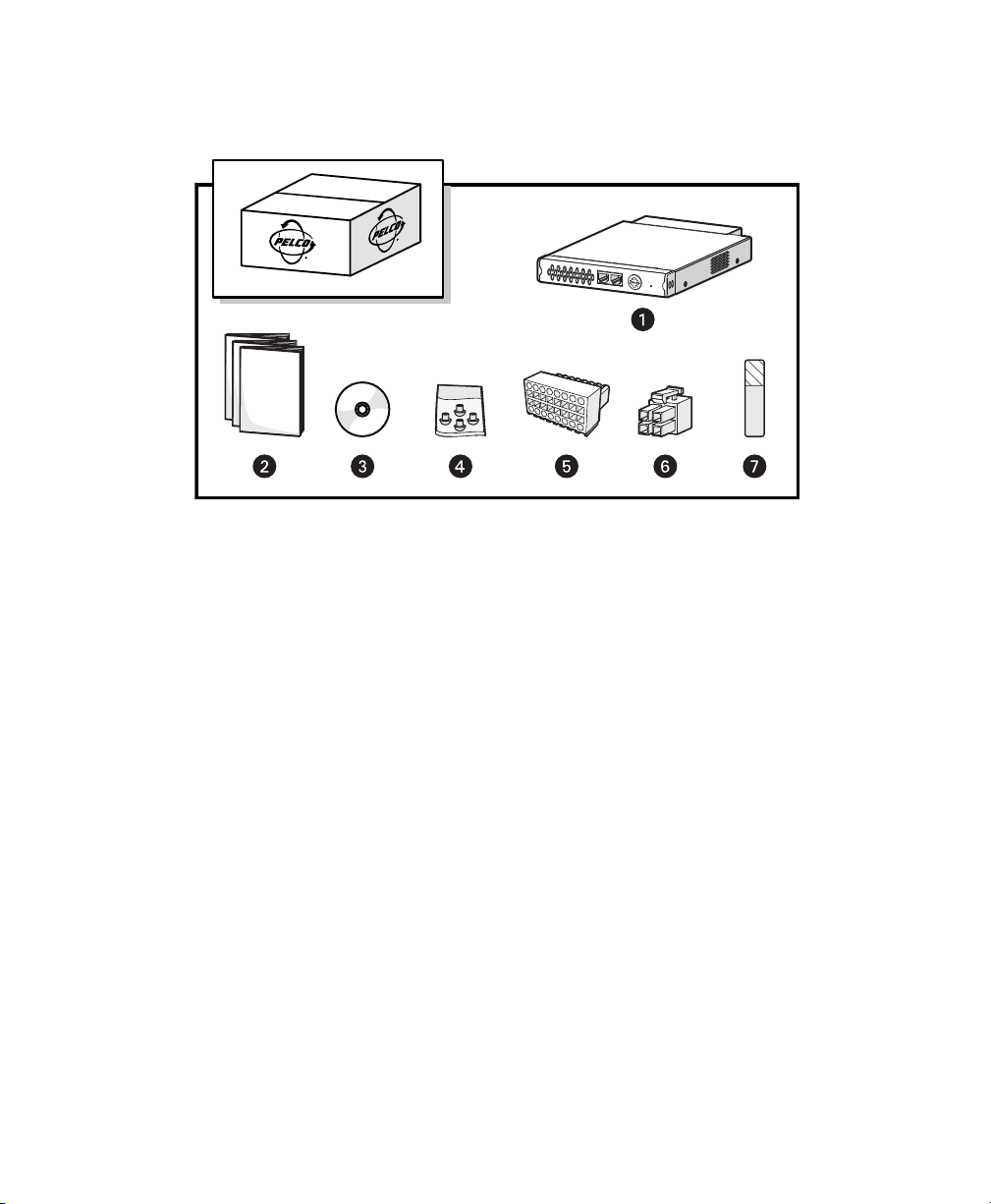
PACKAGE CONTENTS
The following diagram shows the box contents. When installing the unit, refer to this diagram.
NET5400T Series Video Encoder
ì
Installation Manual, Safety Instructions, and Quick Start Guide (1 ea.)
î
Figure 1. Package Contents
Resource Disc
ï
Rubber Feet (4 ea.)
ñ
16-Pin Terminal Block (1 ea.)
ó
4-pin Terminal Block (1 ea.)
r
Pelco Badge Rotation Sticker (1 ea.)
s
NOTE: Since power requirements vary by installation, the NET5400T Series does not include an individual power supply.
You can purchase either the optional NET5400PS single-unit power supply or the RK5200PS-5U rack mount, which includes
two power supplies. Refer to Connecting Power on page 33 for more information on supplying power to the unit.
C4658M-D (12/12) 11
Page 12
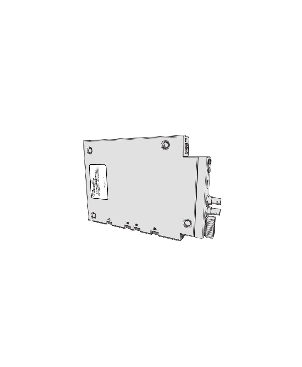
PRODUCT SERIAL NUMBER LABEL PLACEMENT
Product serial number labels help Pelco’s Product Support identify your system and its factory configuration in case the unit
or its components require service.
A label citing your product’s serial number is attached to the bottom panel of the unit. Because rack mounting or other
installation options may obscure the factory-applied label, two additional labels are provided. Attach one of them to your
product documentation or another product location that will not be obscured by installation. The second label is a spare.
To use these labels:
1. On the bottom panel of your unit, locate two small labels, attached with a yellow sticker that reads, “Extra serial
number labels: remove prior to installation.”
2. Remove the yellow sticker and the labels.
3. Peel away the backing from one label and attach it to this installation manual, other product documentation, or an
unobscured product location.
Figure 2. Product Serial Number Label Placement
12 C4658M-D (12/12)
Page 13
Equipment Placement and Rack Mounting
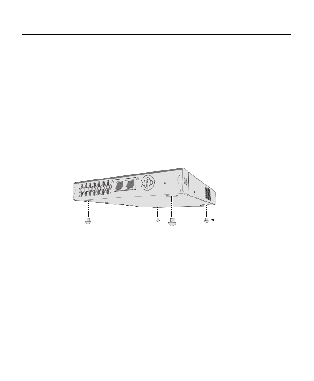
RUBBER FEET
2
1
NET5401T
(POE+)
Use one of the following installation methods for the unit:
• Place the unit on a flat surface, such as a shelf or desktop.
• Mount the unit to a wall using the optional WS5200-4U wall mount kit.
• Install the unit in the optional RK5200PS-5U rack mount kit.
NOTES:
• Each installation method, except the RK5200PS-5U, requires the installation of a separate power supply, either the
NET5400PS (not supplied) or other equipment supplied by the user (refer to Connecting Power on page 33).
• When installing the unit on a desktop, use the rubber feet provided with the unit to protect the desktop from surface
damage. The rubber feet are not needed when mounting the unit in a wall or rack mount.
DESKTOP INSTALLATION
To place the unit on a flat surface, such as a desktop:
1. Attach the rubber feet to the bottom of the unit to prevent surface damage.
Figure 3. Attaching Rubber Feet for Desktop Placement
C4658M-D (12/12) 13
Page 14
2. Position the unit to allow for cable and power cord clearance at the front and rear panels.
1
2
NET5401T
(
PO
E
+
)
WARNING: Do not place the unit on its side; the unit could fall over and cause damage. Placing the unit on its side
also blocks air flow and can cause the unit to overheat.
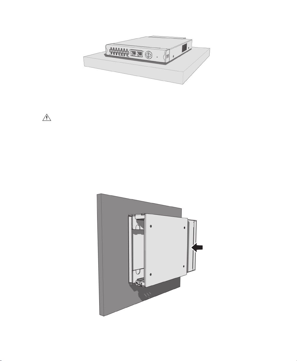
WALL MOUNTING
A single NET5400T Series unit can be mounted to a wall using the optional WS5200-4U wall mount system.
To mount the unit to a wall using the WS5200-4U:
1. Install the WS5200-4U; refer to the WS5200 Series Wall Mount Kit Installation manual.
2. Insert the NET5400T Series unit into the wall mount. Make sure all front and rear panel connectors are accessible.
Figure 4. Desktop Placement
Figure 5. NET5400T and WS5200-4U Wall Mount
14 C4658M-D (12/12)
Page 15

3. Tighten the thumbscrew on the wall mount to secure the unit.
TIGHTEN
THUMBSCREW
RACK MOUNTING
The optional RK5200PS-5U rack mount kit can support up to 12 NET5400T Series units. Each unit connects directly to a
power connector in the rack and is powered by the rack.
NOTES:
• To ensure proper rack ventilation, install a blank module (RK5001B-5U) in each empty slot.
• The RK5200PS-5U supplies only power. It does not provide a dock for any other unit connectors.
• Always leave at least 1 rack unit (RU) of space below the RK5200PS-5U unit. If another unit is installed directly above
an RK5200PS-5U, only the lower unit needs an empty rack space below it.
Figure 6. Tighten the Thumbscrew to Secure the Unit
C4658M-D (12/12) 15
Page 16

To install the unit into a rack mount kit:
TIGHTEN
THUMBSCREW
1. Install the RK5200PS-5U rack mount kit into the rack; refer to the RK5200PS-5U Rack Mount Chassis Installation
manual.
2. Insert the unit into the desired slot.
Figure 7. Multiple Units in an RK5200PS-5U
3. Tighten the thumbscrew on the rack mount to secure the unit into the rack.
Figure 8. Tighten Thumbscrew to Secure the Unit
16 C4658M-D (12/12)
Page 17

PELCO BADGE ORIENTATION
12
NET5401T
12
NET5401T
(POE+)
The Pelco badge on the front panel of the unit can be rotated in quarter turns. If you install the unit on a flat surface, the
Pelco badge will be turned the wrong way.
To rotate the Pelco badge:
1. Use the Pelco badge rotation sticker that came with the unit.
2. Attach the middle portion of the rotation sticker to the badge.
3. Press firmly with your thumb and rotate the badge to its correct position.
4. Remove the rotation sticker from the badge.
Figure 9. Pelco Badge Orientation
C4658M-D (12/12) 17
Page 18

Connections
12
1
1234
2
34
NCCNO A
1 A2 A3 A4
L
4-CHANNEL MODELS
Familiarize yourself with the rear panel before connecting any equipment to the unit. Refer to Connecting a PTZ Device,
Relay, and Alarms on page 24 for a description of the terminal block connections.
Figure 10. Rear Panel for 4-Channel Models
4-Pin Power
ì
Audio In 1 through 4
î
Video In 1 through 4
ï
Relay Connections
ñ
18 C4658M-D (12/12)
RS-422 PTZ Connections
ó
Ground
r
Ground
s
Alarm Connections
t
Page 19

2-CHANNEL MODELS
1
2
21
NCCNO A1 A2 A3 A4
LL
Familiarize yourself with the rear panel before connecting any equipment to the unit. Refer to Connecting a PTZ Device,
Relay, and Alarms on page 24 for a description of the terminal block connections.
Figure 11. Rear Panel for 2-Channel Models
4-Pin Power
ì
Audio Out 1 and 2
î
Audio In 1 and 2
ï
Video In 1
ñ
Video Out 1
ó
Video In 2
r
Video Out 2
s
Relay Connections
t
RS-422 PTZ Connections
u
Ground
~í
Alarm Connections
~â
Ground
~ä
C4658M-D (12/12) 19
Page 20

1-CHANNEL MODELS
LL
NCCNO A1 A2 A3 A4
Familiarize yourself with the rear panel before connecting any equipment to the unit. Refer to Connecting a PTZ Device,
Relay, and Alarms on page 24 for a description of the terminal block connections.
Figure 12. Rear Panel for 1-Channel Models
4-Pin Power
ì
Audio Out
î
Audio In
ï
USB (Reserved)
ñ
Video In
ó
Video Out (Looping)
r
Relay Connections
s
RS-422 PTZ Connections
t
Ground
u
Alarm Connections
~í
Ground
~â
20 C4658M-D (12/12)
Page 21

CONNECTING VIDEO INPUT AND OUTPUT DEVICES
LL
NCCNO A1 A2 A3 A4
CAMERA
The NET5400T Series offers both analog video input and looping video output (available on the 1-channel models).
Figure 13. Video Input and Output
Before installing the unit, make sure the distance from the unit to the video device is less than the maximum distance for
the coaxial cable. Refer to Table A for maximum video coaxial cable distances.
Table A. Video Coaxial Cable Requirements
Cable Type* Maximum Distance
RG59/U 229 m (750 ft)
RG6/U 305 m (1,000 ft)
RG11/U 457 m (1,500 ft)
*Cable requirements:
75-ohm impedance
All-copper center conductor; steel-center conductor cable may result in
poor performance
All-copper braided shield with 95 percent braid coverage
C4658M-D (12/12) 21
Page 22

CONNECTING VIDEO INPUT
The NET5400T Series automatically detects the video standard (PAL or NTSC) and accepts both color and black-white
analog video.
To connect video input:
1. Connect a coaxial cable to the camera or other analog video source.
2. Connect the coaxial cable to the video in connector on the rear panel.
3. If not using looping video, you must set the video termination for the camera. Video termination can be set from the
WS5200 advanced system management software.
The unit supports Coaxitron up-the-coax operation to a PTZ device. When the unit receives a camera control command, it
transmits that command up the coaxial cable to the PTZ device. Since Coaxitron is a single-direction protocol, the PTZ
device cannot return any data to the unit. By default, Coaxitron is disabled.
®
This unit also supports a serial PTZ device that uses the Pelco D protocol, such as the Spectra
cable from the device, and then refer to Connecting a PTZ Device (Pelco D) on page 25 to connect the camera control leads.
dome. Connect the coaxial
CONNECTING LOOPING VIDEO
The NET5400T Series supports looping video on the 1- and 2-channel models. It passes the video input to a monitor or
other analog video device.
To use looping video:
1. Connect a coaxial cable to the video out connector on the rear panel of a 1-channel model.
2. Connect the other end of the coaxial cable to the analog device.
22 C4658M-D (12/12)
Page 23

CONNECTING AUDIO
LL
AUDIO PREAMP
The NET5400T Series supports one audio line input for an amplified audio input device. The unit encodes audio and video
signals simultaneously. This lets you listen to activity in the target area.
To connect an audio input device:
1. Wire the input audio connector. Connect the signal high lead to the connector tip. Connect the common lead to the
connector sleeve. The line input level is 1 Vp-p (0 dBV) nominal, 1.228 Vp-p (+4 dBV) maximum.
2. Connect a line input device to the blue 3.5 mm audio input monaural connector.
Figure 14. Audio Connections
NOTES:
• Audio output is not supported at this time.
• Improper use of audio/visual recording equipment may subject you to civil and criminal penalties, Applicable laws
regarding the use of such capabilities vary between jurisdictions and may require, among other things, express
written consent from the recorded subjects. You are solely responsible for insuring strict compliance with such laws
and for strict adherence to any/all rights of privacy and personalty.
C4658M-D (12/12) 23
Page 24

CONNECTING A PTZ DEVICE, RELAY, AND ALARMS
L
NCCNO
A
1
A
2
A
3
A
4
PIN1 PIN1
PIN 9 PIN 16
The NET5400T Series incorporates a 16-pin terminal block to support the following items:
• PTZ device, such as a dome camera, using the Pelco D protocol (RS-422)
• Relay control, either normally open (N.O.) or normally closed (N.C.)
• Up to four alarm inputs, supervised or unsupervised, using any combination of high and low signals
The terminal block has tension clamps instead of screw terminals. Use a small screwdriver to open the clamp for a
particular lead. Figure 15 shows how to wire the terminal block and connect it to the unit.
NOTE: The terminal block is keyed. It attaches only one way to the video encoder.
Figure 15. Terminal Block Connections
24 C4658M-D (12/12)
Page 25

Table B identifies the pin assignments for the terminal block. An arrow on the rear panel identifies pin 1; on the terminal
block, pin 1 is the left-most lead on the top row (refer to Figure 15).
Table B. PTZ, Relay, and Alarm Pin Assignments
Top Row Bottom Row
Pin Label Lead Pin Label Lead
1 NC Relay Normally Closed 9 TX+ RS-422 Data TX+
2 C Relay Common 10 TX– RS-422 Data TX–
3 NO Relay Normally Open 11 RX– RS-422 Data RX–
4 Ground 12 RX+ RS-422 Data RX+
5A
1 Alarm 1 13 Ground
6A2 Alarm 2 14 Ground
7A
3 Alarm 3 15 Ground
8 A4 Alarm 4 16 Ground
CONNECTING A PTZ DEVICE (PELCO D)
NOTE: To connect a Coaxitron PTZ device, refer to Connecting Video Input on page 22.
The NET5400T Series supports serial camera control using Pelco D (RS-422) for a PTZ device.
When the unit receives a camera control command, it transmits that command to the PTZ device. In 4-wire installations,
the encoder also receives data from the PTZ device, including camera status and alarm states. It then transmits that data
to the command center.
Figure 16 shows how to wire the unit to a Spectra dome (refer to Table B for the specific connector pin assignments).
NOTE: When connecting a PTZ device to the unit, connect the TX+ and TX– leads to the RX+ and RX– leads between the
encoder and the PTZ device.
C4658M-D (12/12) 25
Page 26

By default, the encoder identifies any PTZ device as a fixed camera. You must configure the encoder before you can use
NC
C NO A
1 A2 A3 A4
the PTZ device; refer to the software configuration/operation manual.
COAXIAL CABLE
TRANSMIT
TO SPECTRA
RX–RX+ TX+TX–
RECEIVE
FROM SPECTRA
SPECTRA
Figure 16. Connecting a Spectra Dome
Refer to Table C when installing the PTZ device. It lists the serial port settings that the unit supports.
Table C. Serial Port Options and Defaults
Setting Options Default
Data rate
2400, 4800, 9600, 38400, 115200 2400
(bits per second)
Data bits 5, 6, 7, 8 8
Parity None, Odd, Even None
Stop bits 1, 2 1
NOTE: When using 115200 as the data rate, the following additional settings are used: the Data Bit is set to 8, Parity is
set to No Flow Control, and the stop bit is 1.
26 C4658M-D (12/12)
Page 27

CONNECTING A RELAY DEVICE
NC
C NO A
1 A2 A3 A4
The NET4500T has an output for triggering an external device. It supports both momentary and continuous relay operation.
You can operate the relay interactively, during an active connection, or automatically to coincide with certain events.
Typical applications include activating a door, gate or lock, or switching on lights or other electrical devices.
WARNING: Do not exceed the maximum rating of 30 VDC, 1 A.
Figure 17 shows how to wire the relay with its power source to the video encoder (refer to Table B on page 25 for the
specific connector pin assignments).
LOAD:
LIGHT/SIREN
POWER
NORMALLY
OPEN (N.O.)
EXTERNAL
FUSE
COMMON (C)
MAX 30 VDC, 1A
Figure 17. Connecting a Relay Device
C4658M-D (12/12) 27
Page 28

CONNECTING ALARMS
NORMALLY OPEN
NORMALLY CLOSED
ALARM
GND
+V
+V
ALARM
GND
+V
+V
ALARM
GND
CUT
NO ALARMNO ALARM
GND
ALARM
GND
+V
+V
+V
+V
ALARM
GND
BYPASS
CUT
BYPASS
GND
ALARM
GND
10K 10K
10K
10K
10K
10K
10K
10K
The NET5400T Series offers three alarm inputs for external signaling devices, such as door contacts or motion detectors.
Each encoder supports both normally open and normally closed devices. Each encoder also supports both supervised and
unsupervised alarms.
Once configured, an alarm input can invoke many different activities, including triggering a relay device, sending an alert
to a security office, changing the video recording settings, and storing pre-alarm video to an Endura video recorder. You can
connect switches or contacts directly to the unit without a separate power supply.
Supervised Alarms
When an alarm is configured as a supervised alarm, the unit maintains a constant electrical current through the alarm
circuit (3.3 VDC, 1 kohm). If the alarm circuit length changes, due to an electrical short or a bypass, the voltage fluctuates
from its normal state; therefore, the unit triggers an alarm.
NOTE: Install the 10 kohm resistor as close to the switch as possible.
Figure 18 illustrates the alarm and no alarm conditions of a supervised alarm input. Whether the alarm is normally closed
or normally open, neither a cut nor a bypass can defeat these alarms.
Figure 18. Supervised Alarm Conditions
28 C4658M-D (12/12)
Page 29

Figure 19 illustrates the wiring configuration for supervised alarm inputs.
NORMALLY CLOSED
UNUSED
INPUTS
MUST ALSO
BE WIRED
NORMALLY OPEN
UNUSED
INPUTS
MUST ALSO
BE WIRED
1 K
?
1 K
?
1 K
?
1 K
?
1 K
1 K
?
NORMALLY OPEN
NORMALLY CLOSED
ALARM
GND
+V
+V
ALARM
GND
+V
+V
NO ALARM
GND
ALARM
GND
+V
+V
+V
NO ALARM
GND
CUT
BYPASS
CUT
NO ALARM
GND
NO ALARM
GND
+V
BYPASS
ALARM
GND
Figure 19. Supervised Alarm Input Wiring
Unsupervised Alarms
When an alarm is configured as an unsupervised alarm, the unit only triggers an alarm when the normal alarm state (open
or closed) changes.
Figure 20 illustrates the alarm and no alarm conditions of an unsupervised alarm input. A normally closed alarm input can
be defeated with a bypass. A normally open input can be defeated with a cut.
C4658M-D (12/12) 29
Figure 20. Unsupervised Alarm Conditions
Page 30

Figure 21 illustrates the wiring configuration for unsupervised alarm inputs.
NORMALLY CLOSED
UNUSED
INPUTS
MAY BE
SHORTED
NORMALLY OPEN
UNUSED
INPUTS
MUST BE LEFT
UNWIRED
NC
C NO A
1 A2 A3 A4
Figure 21. Unsupervised Alarm Input Wiring
Alarm Connections
Figure 22 shows how to wire the video encoder to an alarm (refer to Table B on page 25 for the specific connector pin
assignments).
30 C4658M-D (12/12)
A1
Figure 22. Connecting Alarms
Page 31

CONNECTING TO THE NETWORK
12
NET5401T
(POE +)
DAISY CHAIN POE OR NETWORK
Connect the video encoder to the Endura network:
1. Connect a Cat5e (or better) cable to either network port on the front panel.
NOTE: If you are using a PoE or PoE+, no other Cat5e is required. Using both network ports creates a video loop in
the network. Do not use both network ports unless you intend to loop the video.
2. Connect the other end of the network cable to a 100/1000Base-T (or better) port on the Endura network switch.
Figure 23. Connecting to the Endura Network
After you apply power to the encoder (refer to Connecting Power on page 33), the encoder automatically searches the
Endura network for other Endura components. Also, the indicators on the front panel show network connection speed and
status (refer to Front Panel Indicators on page 35).
NOTE: The 1- and 2-channel models support PoE and PoE+ respectively. Be sure to use the network port located at the
right when using PoE or PoE+.
C4658M-D (12/12) 31
Page 32

DAISY-CHAINING SEVERAL UNITS
A maximum of four NET5400T Series units can be connected together in a daisy-chained network. Follow these guidelines
when setting up the daisy chain:
• Always use Cat6 cable with strain relief included at each connector.
• Always follow the cable length guidelines established by the Institute of Electrical and Electronics Engineers (IEEE).
• Use a Gigabit network connection for the unit that is connected to the network.
Network
Figure 24. Daisy-Chained Units Installed in a Rack
32 C4658M-D (12/12)
Page 33

CONNECTING POWER
L
L
N
C
C NO A
1
A
2
A
3
A
4
This product is intended to be supplied with power by a 12 VDC, 24 VAC (except for the NET5404T), or a PoE power supply
(except for the NET5404T) that is UL Listed, Class 2, or a UL Listed ITE power supply marked LPS, such as Pelco's
NET5200PS or RK5200PS-5U. One- and two-channel models can operate from the PoE port.
The unit can be powered from the following sources:
• NET5400PS power supply connects directly to the 4-pin connector on the rear panel of the unit.
• The RK5200PS-5U rack mount kit supplies power through the 4-pin connector on the rear panel of the unit as soon as
it slides into place.
• The 1-channel models support PoE, IEEE 802.3af-2003 (the network port located closest to the Pelco badge).
• The 2-channel models support PoE+, IEEE 802.3at (the network port located closest to the Pelco badge).
Figure 25. Connecting Power
C4658M-D (12/12) 33
Page 34

POWER CONSUMPTION
Use Table D to help you determine the maximum power consumption for each model. Power consumption of the NET5400T
Series varies depending on the number of video channels and the connected power supply.
Table D. Power Consumption Differences
Model Types 12 VDC External Power 24 VAC External Power
12 VDC Power from the
RK5200PS-5U
1-channel models 15 W (52 BTU/h) 15 W (52 BTU/h) 75 W (256 BTU/h)
2-channel models 17.5 W (60 BTU/h) 17.5 W (60 BTU/h) 75 W (256 BTU/h)
4-channel models 27.5 W (94 BTU/h) Not available 70 W (239 BTU/h)
NOTE: Power consumption rates are higher on the RK5200PS-5U because the rack power supports multiple units, cooling
fans, backplane board, and auxiliary devices such as relays and alarms.
Table E. PoE Power Consumption Differences
Model Types Type of PoE Consumption
1-channel models PoE 12 W (41 BTU/h)
2-channel models PoE+ 14 W (48 BTU/h)
4-channel models Not available
RECOMMENDED WIRE GAUGE AND WIRING DISTANCES
Use Table to help identify the necessary wire gauge and maximum cable distance. This table applies to 2-conductor solid
copper wire. (Reduce distance by 10 percent for stranded copper wire.) These maximum distances are based on a
maximum allowable voltage drop of 10 percent.
Table F. Recommended Wire Gauge and Maximum Wiring Distances
Wire Gauge
20 AWG (0.5 mm
2
) 27 m (89 ft) 108 m (356 ft)
18 AWG (1.0 mm2) 42 m (141 ft) 172 m (566 ft)
16 AWG (1.5 mm
14 AWG (2.5 mm
2
) 68 m (224 ft) 274 m (899 ft)
2
) 108 m (357 ft) 435 m (1,428 ft)
12 AWG (4.0 mm2) 172 m (566 ft) 690 m (2,267 ft)
10 AWG (6.0 mm
2
) 274 m (900 ft) 1,097 m (3,600 ft)
Maximum Distance
12 VDC 24 VAC
Connect power to the unit. The Pelco badge (blue) and the status light (green) on the front panel should glow.
34 C4658M-D (12/12)
Page 35

FRONT PANEL INDICATORS
12
1234
NET5404T
Refer to the NET5400T Series Configuration manual for details on setting up any camera that is attached to the unit. You
can also view video from cameras attached to the unit from the WS5200 software or from the VCD5200 video console
display.
4-CHANNEL MODELS
Figure 26. Front Panel Indicators on 4-Channel Models
Video Presence
ì
Network Status
î
Unit Status
ï
RJ-45 Network Ports
ñ
Reserved
ó
C4658M-D (12/12) 35
Page 36

2-CHANNEL MODELS
12
12
NET5402T
(POE +)
12
NET5401T
(POE +)
Figure 27. Front Panel Indicators on 2-Channel Models
Video Presence
ì
Network Status
î
Unit Status
ï
NOTE: The PoE+ network connector also accepts a standard RJ-45 network line.
RJ-45 Network Port
ñ
PoE+ Network Port
ó
Reserved
r
1-CHANNEL MODELS
Figure 28. Front Panel Indicators on 1-Channel Models
Video Presence
ì
Network Status, Line 2
î
RJ-45 Network Port
ó
PoE Network Port
r
Network Status, Line 1
ï
Unit Status
ñ
NOTE: The PoE network port also accepts a standard RJ-45 network line.
36 C4658M-D (12/12)
s
Reserved
Page 37

DESCRIPTIONS OF THE FRONT PANEL INDICATORS
Video presence
Video presence is indicated by one of the following conditions:
• Not Lit: A camera has not been connected yet.
• Green: Camera video is present at the video in connector.
• Red: Video is no longer present; the camera is not functioning properly.
Network status
Network status (connection and speed) is indicated by one of the following conditions:
• Off: The unit is not connected to the network.
• Solid amber: The unit is connected to the network using the 100 Mbps standard.
• Solid red: The unit is connected to the network using the 10 Mbps standard.
• Solid green: The unit is connected to the network using the 1 Gbps standard.
NOTES:
• A blinking light indicates network activity corresponding to the speed based on the color.
• The NET5400T Series video encoder always uses the 100/1000Base-T standard. If the network status light is red,
contact your network administrator or Endura-certified technician.
Pelco badge (power)
The Pelco badge glows blue when the unit has power.
Unit status
Unit status is indicated by one of the following colors:
• Green: The unit is functioning normally.
• Red: The unit is in an error condition.
C4658M-D (12/12) 37
Page 38

Troubleshooting
If the following instructions fail to solve your problem, contact Pelco Product Support at 1-800-289-9100 (USA and Canada)
or 1-559-292-1981 (international) for assistance.
Access the properties windows for the NET5400T Series video encoder on the Endura workstation; refer to the Endura
WS5200 Advanced System Management Software Operation manual.
• Unit serial number: Located on the Properties window and on the product label
• Unit firmware version: Located on the Advanced Properties window, listed for the Encoder Device
NOTE: Do not try to repair the unit yourself. Opening it immediately voids any warranty. Leave maintenance and repairs to
qualified technical personnel. Exchange the defective unit and return it for repair.
Problem Possible Causes Suggested Remedy
Front panel indicators not lit Power turned off Check the power supply
Network connection Faulty network connections Visually inspect all network cables and
Table G. Troubleshooting the NET5400T Series Video Encoder (1 of 2)
connectors at the unit and the network switch
Check the indicators on the network switch
Unit has connected at 100Base-T Contact your network administrator or
Endura-certified technician
Other network connectivity issues Contact your network administrator or
Endura-certified technician
Incorrect cable type is used Always use Cat5e or better cable; if more
than one unit is connected to another in a
daisy-chained network, always use Cat6
cable
No video transmission Faulty cable connections Check all leads, plugs, contacts, and
connections
Defective camera Connect local monitor and check camera
function
Defective encoder Check camera on a different encoder
No looping video on local monitor
38 C4658M-D (12/12)
Faulty cable connections Check all leads, plugs, contacts, and
connections
Page 39

Table G. Troubleshooting the NET5400T Series Video Encoder (2 of 2)
No audio transmission to receiver Volume set too low at receiver Adjust volume control at receiver
Audio service not enabled Enable the audio service on the camera setup
screen; refer to the software configuration/
operation manual
Faulty cable connection Check all leads, plugs, contacts, and
connections
Defective audio devices or
connections
Troubleshoot all connected audio devices
Connect different audio hardware and check
audio function
Defective encoder Check audio devices on a different encoder
Cannot control PTZ cameras or
other devices
Camera protocol setting does not
match encoder protocol setting
Change the protocol setting for the camera on
the Endura workstation
Change the camera to the correct protocol
setting
Other PTZ settings are not correct Change the camera settings on the Endura
workstation
Faulty camera control cable
connections
Check all cable connections; make sure all
plugs are properly connected
The unit is not ready for
operation after firmware upload
C4658M-D (12/12) 39
Voltage failure during programming
of update file
Replace the device and have it checked
by Pelco
Page 40

Specifications
SYSTEM
Operating System Linux
User Interface Remote operation from WS5070, WS5200 software, or VCD5200;
VIDEO/AUDIO
Video Standards NTSC/PAL/EIA/CCIR composite
Video Coding H.264 high, medium, or low profiles
Video Streams 2 independently configurable video streams for each channel;
Video Resolutions NTSCPAL
4CIF 704 x 480 704 x 576
2CIF 704 x 240704 x 288
CIF 352 x 240352 x 288
Video Inputs/Connector Type 1, 2, or 4 BNC inputs; Hi-Z/75 ohms impedance
Video Looping 1-channel models only
Audio Encoding G.711 speech codec
Audio Bit Rate 64 kbps
Audio Levels 1 Vp-p (0 dBV) nominal, 1.228 V-p-p (+4 dBU) maximum, 10 kohms
Audio Connectors 1, 3.5 mm monaural
Connector Tip Signal high (input)
Connector Sleeve Common
Audio Input Line in
®
Web-based remote operation is also available
2 unicast streams for each channel
PTZ CONTROL
PTZ Interface RS-422, video in
PTZ Protocols Pelco D (RS-422), Coaxitron
ALARMS/RELAYS
Alarm Inputs 1, 2, or 4 configurable, 3.3 VDC, 10 kohms, triggered; uses 6 of 16 pins on terminal
block connector; supervised and unsupervised
Relay Output 1, form-C relay, 30 VDC, 1 A; uses 3 of 16 pins on terminal block connector
40 C4658M-D (12/12)
Page 41

VIDEO ACTIVITY DETECTION
Zones 3 plus 1 background zone
Zone Types Any shape, user-definable in 16 x 16 pixel blocks
Sensitivity/Threshold Adjustable per zone
AUXILIARY INTERFACES
Serial Pelco D protocols (RS-422); uses 4 of 16 pins on terminal block connector
Terminal Block Connector 16-pin: Pelco D protocols (RS-422), 4 alarm inputs, 1 relay output
FRONT PANEL INDICATORS/FUNCTIONS
Network RJ-45, 100/1000Base-T
Power Blue
Status Green, amber, red
Network Link/Speed Amber, red
Network Activity Green
Video Green, red
POWER
Power Consumption Varies per number of connected channels power source
Power Input 12 VDC ±10%
24 VAC ±10% (1- and 2-channel models)
Power Connectors
4-Pin For RK5200PS-5U or NET5400PS; all models
PoE 1-channel models
PoE+ 2-channel models
ENVIRONMENTAL
Operating Temperature
1- and 2-channel models 0° to 45°C (32° to 113°F) at unit air intake (front of unit)
4-channel models 0° to 35°C (32° to 95°F) at unit air intake (front of unit)
Storage Temperature –40° to 65°C (–40° to 149°F)
Operating Humidity 20% to 80%, noncondensing
Maximum Humidity Gradient 10% per hour
Operating Altitude –16 to 3,048 m (–50 to 10,000 ft)
Operating Vibration 0.25 G at 3 to 200 Hz at a sweep rate of 0.5 octave/minute
C4658M-D (12/12) 41
Page 42

PHYSICAL
REVISION HISTORY
Manual # Date Comments
C4658M 3/10 Original version.
C4658M-A 4/10 Added instructions for daisy-chaining; deleted MPEG-4 as a supported file type.
C4658M-B 5/10 Corrected the callout descriptions on Figure 11.
C4658M-C 6/10 Reformatted to fit on a smaller page size.
C4658M-D 12/12 Corrected information about which power source is supported by each model; removed incorrect text about supported serial PTZ
devices.
Construction Sheet metal
Finish Gray metallic with black end caps, black matte finish
Dimension 22.2 x 16.5 x 3.0 cm
(8.75" D x 6.5" W x 1.2" H)
Mounting Desktop (feet), wall, or rack with options
Unit Weight
1- and 2-channel models 0.9 kg (2.0 lb)
1- and 2-channel models 1.3 kg (2.9 lb)
STANDARDS/ORGANIZATIONS
• Pelco is a member of the MPEG-4 Industry Forum
• Pelco is a member of the Universal Plug and Play (UPnP) Forum
• Pelco is a member of the Universal Serial Bus (USB) Implementers Forum
• Pelco is a contributor to the International Standards for Organization/Electrotechnical Commission (ISO/IEC) Joint
Technical Committee 1 (JTC1), “Information Technology,” Subcommittee 29, Working Group 11
• Compliance, ISO/IECv 14496 standard (also known as MPEG-4)
• Compliant with International Telecommunication Union (ITU) Recommendation G.711, “Pulse Code Modulations
(PCM) of Voice Frequencies”
42 C4658M-D (12/12)
Page 43

PRODUCT WARRANTY AND RETURN INFORMATION
WARRANTY
Pelco will repair or replace, without charge, any merchandise proved defective
in material or workmanship for a period of one year after the date of
shipment.
Exceptions to this warranty are as noted below:
• Five years:
– Fiber optic products
– Unshielded Twisted Pair (UTP) transmission products
– CC3701H-2, CC3701H-2X, CC3751H-2, CC3651H-2X, MC3651H-2, and
MC3651H-2X camera models
• Three years:
– FD Series and BU Series analog camera models
– Fixed network cameras and network dome cameras with Sarix
technology
– Sarix thermal imaging products (TI and ESTI Series)
– Fixed analog camera models (C20 Series, CCC1390H Series, C10DN
Series, and C10CH Series)
– EH1500 Series enclosures
®
– Spectra
– Spectra HD dome products
– Camclosure
– DX Series video recorders (except DX9000 Series which is covered for a
– Endura
– Genex
IV products (including Spectra IV IP)
®
IS Series integrated camera systems
period of one year), DVR5100 Series digital video recorders, Digital
®
Series hardware products, DVX Series digital video recorders,
Sentry
and NVR300 Series network video recorders
®
Series distributed network-based video products
®
Series products (multiplexers, server, and keyboard)
– PMCL200/300/400 Series LCD monitors
– PMCL5xxF Series and PMCL5xxNB Series LCD monitors
– PMCL5xxxBL Series LED monitors
• Two years:
– Standard varifocal, fixed focal, and motorized zoom lenses
– DF5/DF8 Series fixed dome products
®
– Legacy
– Spectra III
Series integrated positioning systems
™
, Spectra Mini, Spectra Mini IP, Esprit®, ExSite®, ExSite IP,
and PS20 scanners, including when used in continuous motion
applications
– Esprit Ti and TI2500 Series thermal imaging products
– Esprit and WW5700 Series window wiper (excluding wiper blades)
– CM6700/CM6800/CM9700 Series matrix
– Digital Light Processing (DLP
The lamp and color wheel will be covered for a period of 90 days. The
air filter is not covered under warranty.
®
) displays (except lamp and color wheel).
• Six months:
– All pan and tilts, scanners, or preset lenses used in continuous motion
applications (preset scan, tour, and auto scan modes)
Pelco will warrant all replacement parts and repairs for 90 days from the date
of Pelco shipment. All goods requiring warranty repair shall be sent freight
prepaid to a Pelco designated location. Repairs made necessary by reason of
misuse, alteration, normal wear, or accident are not covered under this
warranty.
Pelco assumes no risk and shall be subject to no liability for damages or loss
resulting from the specific use or application made of the Products. Pelco’s
liability for any claim, whether based on breach of contract, negligence,
infringement of any rights of any party or product liability, relating to the
Products shall not exceed the price paid by the Dealer to Pelco for such
®
Products. In no event will Pelco be liable for any special, incidental, or
consequential damages (including loss of use, loss of profit, and claims of third
parties) however caused, whether by the negligence of Pelco or otherwise.
The above warranty provides the Dealer with specific legal rights. The Dealer
may also have additional rights, which are subject to variation from state to
state.
If a warranty repair is required, the Dealer must contact Pelco at (800) 2899100 or (559) 292-1981 to obtain a Repair Authorization number (RA), and
provide the following information:
1. Model and serial number
2. Date of shipment, P.O. number, sales order number, or Pelco invoice number
3. Details of the defect or problem
If there is a dispute regarding the warranty of a product that does not fall
under the warranty conditions stated above, please include a written
explanation with the product when returned.
Method of return shipment shall be the same or equal to the method by which
the item was received by Pelco.
RETURNS
To expedite parts returned for repair or credit, please call Pelco at (800) 2899100 or (559) 292-1981 to obtain an authorization number (CA number if
returned for credit, and RA number if returned for repair) and designated return
location.
All merchandise returned for credit may be subject to a 20 percent restocking
and refurbishing charge.
Goods returned for repair or credit should be clearly identified with
the assigned CA or RA number and freight should be prepaid.
Revised 10-9-12
The materials used in the manufacture of this document and its components are compliant to the requirements of Directive 2002/95/EC.
This equipment contains electrical or electronic components that must be recycled properly to comply with Directive 2002/96/EC of the European Union
regarding the disposal of waste electrical and electronic equipment (WEEE). Contact your local dealer for procedures for recycling this equipment.
Pelco, the Pelco logo, and other trademarks associat ed with Pelco products referred to in this publication are trademarks of Pelco, Inc. or its affiliate s. © Copyright 2012, Pelco, Inc.
ONVIF and the ONVIF logo are trademarks of ONVIF Inc. All other product names and services are the property of their respective companies. All rights reserved.
Product specifications and availability are subject to change without notice.
Page 44

Pelco by Schneider Electric 3500 Pelco Way Clovis, California 93612-5699 United States
USA & Canada Tel (800) 289-9100 Fax (800) 289-9150
International Tel +1 (559) 292-1981 Fax +1 (559) 348-1120
www.pelco.com www.pelco.com/community
 Loading...