

Page 1
OPERATION
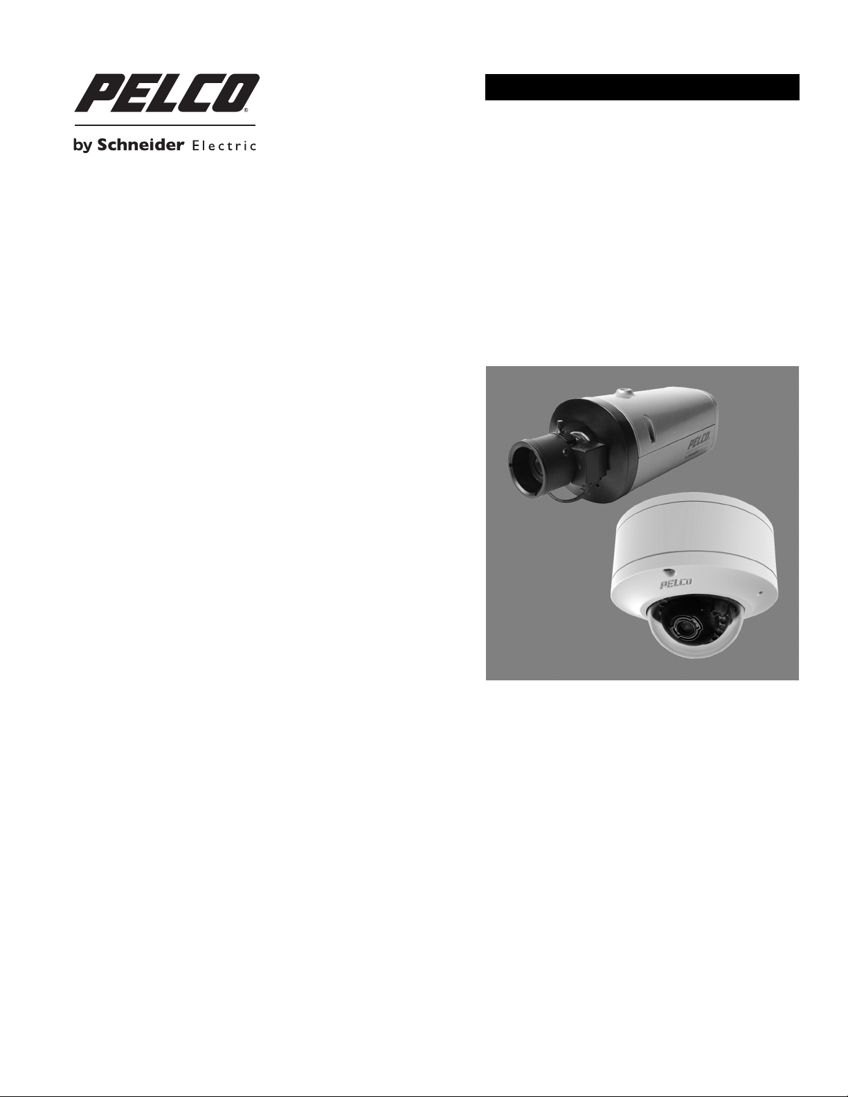
IME and IXE Series Network IP Cameras
Sarix® Box and Mini Dome Cameras
with SureVision Technology
C2270M (7/13)
Page 2

2 C2270M (7/13)
Page 3

Contents
Important Notices . . . . . . . . . . . . . . . . . . . . . . . . . . . . . . . . . . . . . . . . . . . . . . . . . . . . . . . . . . . . . . . . . . . . . . . . . . . . . . . . . . . . . . . . . . . . . . . . . . . . . 5
Legal Notice . . . . . . . . . . . . . . . . . . . . . . . . . . . . . . . . . . . . . . . . . . . . . . . . . . . . . . . . . . . . . . . . . . . . . . . . . . . . . . . . . . . . . . . . . . . . . . . . . . . . . 5
Regulatory Notices . . . . . . . . . . . . . . . . . . . . . . . . . . . . . . . . . . . . . . . . . . . . . . . . . . . . . . . . . . . . . . . . . . . . . . . . . . . . . . . . . . . . . . . . . . . . . . . . 5
Video Quality Caution . . . . . . . . . . . . . . . . . . . . . . . . . . . . . . . . . . . . . . . . . . . . . . . . . . . . . . . . . . . . . . . . . . . . . . . . . . . . . . . . . . . . . . . . . . . . . . 5
Open Source Software Notice . . . . . . . . . . . . . . . . . . . . . . . . . . . . . . . . . . . . . . . . . . . . . . . . . . . . . . . . . . . . . . . . . . . . . . . . . . . . . . . . . . . . . . .5
Warranty Statement . . . . . . . . . . . . . . . . . . . . . . . . . . . . . . . . . . . . . . . . . . . . . . . . . . . . . . . . . . . . . . . . . . . . . . . . . . . . . . . . . . . . . . . . . . . . . . . 5
Introduction . . . . . . . . . . . . . . . . . . . . . . . . . . . . . . . . . . . . . . . . . . . . . . . . . . . . . . . . . . . . . . . . . . . . . . . . . . . . . . . . . . . . . . . . . . . . . . . . . . . . . . . . . . 6
Operation . . . . . . . . . . . . . . . . . . . . . . . . . . . . . . . . . . . . . . . . . . . . . . . . . . . . . . . . . . . . . . . . . . . . . . . . . . . . . . . . . . . . . . . . . . . . . . . . . . . . . . . . . . . . 7
Camera Configuration Sequence . . . . . . . . . . . . . . . . . . . . . . . . . . . . . . . . . . . . . . . . . . . . . . . . . . . . . . . . . . . . . . . . . . . . . . . . . . . . . . . . . . . . . 7
Minimum System Requirements . . . . . . . . . . . . . . . . . . . . . . . . . . . . . . . . . . . . . . . . . . . . . . . . . . . . . . . . . . . . . . . . . . . . . . . . . . . . . . . . . . . . . 7
Accessing the IP Camera . . . . . . . . . . . . . . . . . . . . . . . . . . . . . . . . . . . . . . . . . . . . . . . . . . . . . . . . . . . . . . . . . . . . . . . . . . . . . . . . . . . . . . . . . . . 7
Zoom and Focus Controls. . . . . . . . . . . . . . . . . . . . . . . . . . . . . . . . . . . . . . . . . . . . . . . . . . . . . . . . . . . . . . . . . . . . . . . . . . . . . . . . . . . . . . . . . . . . . . . .8
Live Video Page . . . . . . . . . . . . . . . . . . . . . . . . . . . . . . . . . . . . . . . . . . . . . . . . . . . . . . . . . . . . . . . . . . . . . . . . . . . . . . . . . . . . . . . . . . . . . . . . . . . . . . . 8
Live Video Page Icons . . . . . . . . . . . . . . . . . . . . . . . . . . . . . . . . . . . . . . . . . . . . . . . . . . . . . . . . . . . . . . . . . . . . . . . . . . . . . . . . . . . . . . . . . . . . . . 8
Keyboard Shortcuts. . . . . . . . . . . . . . . . . . . . . . . . . . . . . . . . . . . . . . . . . . . . . . . . . . . . . . . . . . . . . . . . . . . . . . . . . . . . . . . . . . . . . . . . . . . . . . . .8
Selecting a Stream . . . . . . . . . . . . . . . . . . . . . . . . . . . . . . . . . . . . . . . . . . . . . . . . . . . . . . . . . . . . . . . . . . . . . . . . . . . . . . . . . . . . . . . . . . . . . . . . 9
Taking a Snapshot . . . . . . . . . . . . . . . . . . . . . . . . . . . . . . . . . . . . . . . . . . . . . . . . . . . . . . . . . . . . . . . . . . . . . . . . . . . . . . . . . . . . . . . . . . . . . . . 10
Logging On to the Camera . . . . . . . . . . . . . . . . . . . . . . . . . . . . . . . . . . . . . . . . . . . . . . . . . . . . . . . . . . . . . . . . . . . . . . . . . . . . . . . . . . . . . . 7
Primary Stream and Secondary Stream. . . . . . . . . . . . . . . . . . . . . . . . . . . . . . . . . . . . . . . . . . . . . . . . . . . . . . . . . . . . . . . . . . . . . . . . . . . . 9
Quickview Stream . . . . . . . . . . . . . . . . . . . . . . . . . . . . . . . . . . . . . . . . . . . . . . . . . . . . . . . . . . . . . . . . . . . . . . . . . . . . . . . . . . . . . . . . . . . . 9
Event Stream . . . . . . . . . . . . . . . . . . . . . . . . . . . . . . . . . . . . . . . . . . . . . . . . . . . . . . . . . . . . . . . . . . . . . . . . . . . . . . . . . . . . . . . . . . . . . . . .9
Unicast . . . . . . . . . . . . . . . . . . . . . . . . . . . . . . . . . . . . . . . . . . . . . . . . . . . . . . . . . . . . . . . . . . . . . . . . . . . . . . . . . . . . . . . . . . . . . . . . . . . . . 9
Multicast . . . . . . . . . . . . . . . . . . . . . . . . . . . . . . . . . . . . . . . . . . . . . . . . . . . . . . . . . . . . . . . . . . . . . . . . . . . . . . . . . . . . . . . . . . . . . . . . . . . 9
Throttle. . . . . . . . . . . . . . . . . . . . . . . . . . . . . . . . . . . . . . . . . . . . . . . . . . . . . . . . . . . . . . . . . . . . . . . . . . . . . . . . . . . . . . . . . . . . . . . . . . . .10
Settings Page. . . . . . . . . . . . . . . . . . . . . . . . . . . . . . . . . . . . . . . . . . . . . . . . . . . . . . . . . . . . . . . . . . . . . . . . . . . . . . . . . . . . . . . . . . . . . . . . . . . . . . . . 10
Accessing the Camera Menus . . . . . . . . . . . . . . . . . . . . . . . . . . . . . . . . . . . . . . . . . . . . . . . . . . . . . . . . . . . . . . . . . . . . . . . . . . . . . . . . . . . . . .10
System Tab . . . . . . . . . . . . . . . . . . . . . . . . . . . . . . . . . . . . . . . . . . . . . . . . . . . . . . . . . . . . . . . . . . . . . . . . . . . . . . . . . . . . . . . . . . . . . . . . . . . . . . . . . 10
Changing the Device Name . . . . . . . . . . . . . . . . . . . . . . . . . . . . . . . . . . . . . . . . . . . . . . . . . . . . . . . . . . . . . . . . . . . . . . . . . . . . . . . . . . . . . . . . 11
Enabling LEDs . . . . . . . . . . . . . . . . . . . . . . . . . . . . . . . . . . . . . . . . . . . . . . . . . . . . . . . . . . . . . . . . . . . . . . . . . . . . . . . . . . . . . . . . . . . . . . . . . . . 11
Configuring SMTP Server . . . . . . . . . . . . . . . . . . . . . . . . . . . . . . . . . . . . . . . . . . . . . . . . . . . . . . . . . . . . . . . . . . . . . . . . . . . . . . . . . . . . . . . . . . 11
Configuring Time Server Settings. . . . . . . . . . . . . . . . . . . . . . . . . . . . . . . . . . . . . . . . . . . . . . . . . . . . . . . . . . . . . . . . . . . . . . . . . . . . . . . . . . . . 12
Customizing the Appearance of the Text Overlay . . . . . . . . . . . . . . . . . . . . . . . . . . . . . . . . . . . . . . . . . . . . . . . . . . . . . . . . . . . . . . . . . . . . . . . 12
Customizing the Appearance of the Image Overlay. . . . . . . . . . . . . . . . . . . . . . . . . . . . . . . . . . . . . . . . . . . . . . . . . . . . . . . . . . . . . . . . . . . . . . 12
Generating a System Log . . . . . . . . . . . . . . . . . . . . . . . . . . . . . . . . . . . . . . . . . . . . . . . . . . . . . . . . . . . . . . . . . . . . . . . . . . . . . . . . . . . . . . . . . .13
Rebooting the Camera . . . . . . . . . . . . . . . . . . . . . . . . . . . . . . . . . . . . . . . . . . . . . . . . . . . . . . . . . . . . . . . . . . . . . . . . . . . . . . . . . . . . . . . . . . . . 13
Restoring All Camera Defaults . . . . . . . . . . . . . . . . . . . . . . . . . . . . . . . . . . . . . . . . . . . . . . . . . . . . . . . . . . . . . . . . . . . . . . . . . . . . . . . . . . . . . .13
Downloading a Full Backup of Camera Settings . . . . . . . . . . . . . . . . . . . . . . . . . . . . . . . . . . . . . . . . . . . . . . . . . . . . . . . . . . . . . . . . . . . . . . . . 13
Uploading a Backup File to Restore Camera Settings . . . . . . . . . . . . . . . . . . . . . . . . . . . . . . . . . . . . . . . . . . . . . . . . . . . . . . . . . . . . . . . . . . . . 14
Network Tab . . . . . . . . . . . . . . . . . . . . . . . . . . . . . . . . . . . . . . . . . . . . . . . . . . . . . . . . . . . . . . . . . . . . . . . . . . . . . . . . . . . . . . . . . . . . . . . . . . . . . . . . 14
Changing the Host Name . . . . . . . . . . . . . . . . . . . . . . . . . . . . . . . . . . . . . . . . . . . . . . . . . . . . . . . . . . . . . . . . . . . . . . . . . . . . . . . . . . . . . . . . . . 15
Changing the HTTP Port . . . . . . . . . . . . . . . . . . . . . . . . . . . . . . . . . . . . . . . . . . . . . . . . . . . . . . . . . . . . . . . . . . . . . . . . . . . . . . . . . . . . . . . . . . . 15
Changing the HTTPS Port . . . . . . . . . . . . . . . . . . . . . . . . . . . . . . . . . . . . . . . . . . . . . . . . . . . . . . . . . . . . . . . . . . . . . . . . . . . . . . . . . . . . . . . . . . 15
Changing the RTSP Port . . . . . . . . . . . . . . . . . . . . . . . . . . . . . . . . . . . . . . . . . . . . . . . . . . . . . . . . . . . . . . . . . . . . . . . . . . . . . . . . . . . . . . . . . . . 16
Turning On DHCP . . . . . . . . . . . . . . . . . . . . . . . . . . . . . . . . . . . . . . . . . . . . . . . . . . . . . . . . . . . . . . . . . . . . . . . . . . . . . . . . . . . . . . . . . . . . . . . . 16
Turning Off DHCP . . . . . . . . . . . . . . . . . . . . . . . . . . . . . . . . . . . . . . . . . . . . . . . . . . . . . . . . . . . . . . . . . . . . . . . . . . . . . . . . . . . . . . . . . . . . . . . . 16
Configuring IPv6 Settings . . . . . . . . . . . . . . . . . . . . . . . . . . . . . . . . . . . . . . . . . . . . . . . . . . . . . . . . . . . . . . . . . . . . . . . . . . . . . . . . . . . . . . . . . . 17
Selecting the Secure Sockets Layer Mode. . . . . . . . . . . . . . . . . . . . . . . . . . . . . . . . . . . . . . . . . . . . . . . . . . . . . . . . . . . . . . . . . . . . . . . . . . . . . 18
Generating a Self-Signed Certificate . . . . . . . . . . . . . . . . . . . . . . . . . . . . . . . . . . . . . . . . . . . . . . . . . . . . . . . . . . . . . . . . . . . . . . . . . . . .18
Deleting a Self-Signed Certificate. . . . . . . . . . . . . . . . . . . . . . . . . . . . . . . . . . . . . . . . . . . . . . . . . . . . . . . . . . . . . . . . . . . . . . . . . . . . . . . 18
Generating a Certificate Request . . . . . . . . . . . . . . . . . . . . . . . . . . . . . . . . . . . . . . . . . . . . . . . . . . . . . . . . . . . . . . . . . . . . . . . . . . . . . . . 18
Enabling Secure Shell . . . . . . . . . . . . . . . . . . . . . . . . . . . . . . . . . . . . . . . . . . . . . . . . . . . . . . . . . . . . . . . . . . . . . . . . . . . . . . . . . . . . . . . . . . . . . 19
Configuring the 802.1x Port Security Settings . . . . . . . . . . . . . . . . . . . . . . . . . . . . . . . . . . . . . . . . . . . . . . . . . . . . . . . . . . . . . . . . . . . . . . . . . . 19
Selecting SNMP Settings . . . . . . . . . . . . . . . . . . . . . . . . . . . . . . . . . . . . . . . . . . . . . . . . . . . . . . . . . . . . . . . . . . . . . . . . . . . . . . . . . . . . . . . . . . 20
C2270M (7/13) 3
Page 4

Configuring SNMP V2c . . . . . . . . . . . . . . . . . . . . . . . . . . . . . . . . . . . . . . . . . . . . . . . . . . . . . . . . . . . . . . . . . . . . . . . . . . . . . . . . . . . . . . .20
Configuring SNMP V3 . . . . . . . . . . . . . . . . . . . . . . . . . . . . . . . . . . . . . . . . . . . . . . . . . . . . . . . . . . . . . . . . . . . . . . . . . . . . . . . . . . . . . . . . 20
Imaging Tab . . . . . . . . . . . . . . . . . . . . . . . . . . . . . . . . . . . . . . . . . . . . . . . . . . . . . . . . . . . . . . . . . . . . . . . . . . . . . . . . . . . . . . . . . . . . . . . . . . . . . . . . . 21
Configuring the Orientation of the Scene. . . . . . . . . . . . . . . . . . . . . . . . . . . . . . . . . . . . . . . . . . . . . . . . . . . . . . . . . . . . . . . . . . . . . . . . . . . . . . 22
Changing the Digital Processing Settings . . . . . . . . . . . . . . . . . . . . . . . . . . . . . . . . . . . . . . . . . . . . . . . . . . . . . . . . . . . . . . . . . . . . . . . . . . . . . 22
Selecting Exposure Settings. . . . . . . . . . . . . . . . . . . . . . . . . . . . . . . . . . . . . . . . . . . . . . . . . . . . . . . . . . . . . . . . . . . . . . . . . . . . . . . . . . . . . . . . 23
Day Night Settings . . . . . . . . . . . . . . . . . . . . . . . . . . . . . . . . . . . . . . . . . . . . . . . . . . . . . . . . . . . . . . . . . . . . . . . . . . . . . . . . . . . . . . . . . . . . . . . 23
Selecting Day Night Auto Mode . . . . . . . . . . . . . . . . . . . . . . . . . . . . . . . . . . . . . . . . . . . . . . . . . . . . . . . . . . . . . . . . . . . . . . . . . . . . . . . .23
Selecting Day Night Manual Mode . . . . . . . . . . . . . . . . . . . . . . . . . . . . . . . . . . . . . . . . . . . . . . . . . . . . . . . . . . . . . . . . . . . . . . . . . . . . . . 23
Configuring Auto Focus Settings . . . . . . . . . . . . . . . . . . . . . . . . . . . . . . . . . . . . . . . . . . . . . . . . . . . . . . . . . . . . . . . . . . . . . . . . . . . . . . . . 24
Configuring Manual Focus Settings . . . . . . . . . . . . . . . . . . . . . . . . . . . . . . . . . . . . . . . . . . . . . . . . . . . . . . . . . . . . . . . . . . . . . . . . . . . . . . . . . . 24
Selecting Tone Map Settings . . . . . . . . . . . . . . . . . . . . . . . . . . . . . . . . . . . . . . . . . . . . . . . . . . . . . . . . . . . . . . . . . . . . . . . . . . . . . . . . . . . . . . . 25
Turning On Window Blanking. . . . . . . . . . . . . . . . . . . . . . . . . . . . . . . . . . . . . . . . . . . . . . . . . . . . . . . . . . . . . . . . . . . . . . . . . . . . . . . . . . . . . . . 25
Turning Off Window Blanking . . . . . . . . . . . . . . . . . . . . . . . . . . . . . . . . . . . . . . . . . . . . . . . . . . . . . . . . . . . . . . . . . . . . . . . . . . . . . . . . . . . . . . 25
Deleting a Window Blanking Area . . . . . . . . . . . . . . . . . . . . . . . . . . . . . . . . . . . . . . . . . . . . . . . . . . . . . . . . . . . . . . . . . . . . . . . . . . . . . . . . . . .26
Restoring Window Blanking Defaults . . . . . . . . . . . . . . . . . . . . . . . . . . . . . . . . . . . . . . . . . . . . . . . . . . . . . . . . . . . . . . . . . . . . . . . . . . . . . . . . 26
A/V Streams Tab . . . . . . . . . . . . . . . . . . . . . . . . . . . . . . . . . . . . . . . . . . . . . . . . . . . . . . . . . . . . . . . . . . . . . . . . . . . . . . . . . . . . . . . . . . . . . . . . . . . . .26
Selecting a Video Preset Configuration . . . . . . . . . . . . . . . . . . . . . . . . . . . . . . . . . . . . . . . . . . . . . . . . . . . . . . . . . . . . . . . . . . . . . . . . . . . . . . .26
Configuring a Custom Video Stream Configuration . . . . . . . . . . . . . . . . . . . . . . . . . . . . . . . . . . . . . . . . . . . . . . . . . . . . . . . . . . . . . . . . . . . . . .27
Compression Standards. . . . . . . . . . . . . . . . . . . . . . . . . . . . . . . . . . . . . . . . . . . . . . . . . . . . . . . . . . . . . . . . . . . . . . . . . . . . . . . . . . . . . . .27
Resolution and Recommended Bit and Image rates . . . . . . . . . . . . . . . . . . . . . . . . . . . . . . . . . . . . . . . . . . . . . . . . . . . . . . . . . . . . . . . . . 27
Image Rate. . . . . . . . . . . . . . . . . . . . . . . . . . . . . . . . . . . . . . . . . . . . . . . . . . . . . . . . . . . . . . . . . . . . . . . . . . . . . . . . . . . . . . . . . . . . . . . . . 27
Bit Rate . . . . . . . . . . . . . . . . . . . . . . . . . . . . . . . . . . . . . . . . . . . . . . . . . . . . . . . . . . . . . . . . . . . . . . . . . . . . . . . . . . . . . . . . . . . . . . . . . . . 28
I-Frame Interval . . . . . . . . . . . . . . . . . . . . . . . . . . . . . . . . . . . . . . . . . . . . . . . . . . . . . . . . . . . . . . . . . . . . . . . . . . . . . . . . . . . . . . . . . . . . . 28
Quality of Service for Differentiated Services Code Point . . . . . . . . . . . . . . . . . . . . . . . . . . . . . . . . . . . . . . . . . . . . . . . . . . . . . . . . . . . . 28
Endura Signing. . . . . . . . . . . . . . . . . . . . . . . . . . . . . . . . . . . . . . . . . . . . . . . . . . . . . . . . . . . . . . . . . . . . . . . . . . . . . . . . . . . . . . . . . . . . . . 28
Profile. . . . . . . . . . . . . . . . . . . . . . . . . . . . . . . . . . . . . . . . . . . . . . . . . . . . . . . . . . . . . . . . . . . . . . . . . . . . . . . . . . . . . . . . . . . . . . . . . . . . . 28
Rate Control . . . . . . . . . . . . . . . . . . . . . . . . . . . . . . . . . . . . . . . . . . . . . . . . . . . . . . . . . . . . . . . . . . . . . . . . . . . . . . . . . . . . . . . . . . . . . . . . 28
Selecting Audio Configuration Settings . . . . . . . . . . . . . . . . . . . . . . . . . . . . . . . . . . . . . . . . . . . . . . . . . . . . . . . . . . . . . . . . . . . . . . . . . . . . . . . 29
Users Tab . . . . . . . . . . . . . . . . . . . . . . . . . . . . . . . . . . . . . . . . . . . . . . . . . . . . . . . . . . . . . . . . . . . . . . . . . . . . . . . . . . . . . . . . . . . . . . . . . . . . . . . . . . .30
Selecting the Users and Groups Settings. . . . . . . . . . . . . . . . . . . . . . . . . . . . . . . . . . . . . . . . . . . . . . . . . . . . . . . . . . . . . . . . . . . . . . . . . . . . . .30
Enabling Remote Mode . . . . . . . . . . . . . . . . . . . . . . . . . . . . . . . . . . . . . . . . . . . . . . . . . . . . . . . . . . . . . . . . . . . . . . . . . . . . . . . . . . . . . . . . . . . 31
Creating a New User . . . . . . . . . . . . . . . . . . . . . . . . . . . . . . . . . . . . . . . . . . . . . . . . . . . . . . . . . . . . . . . . . . . . . . . . . . . . . . . . . . . . . . . . . . . . . 31
Editing a User . . . . . . . . . . . . . . . . . . . . . . . . . . . . . . . . . . . . . . . . . . . . . . . . . . . . . . . . . . . . . . . . . . . . . . . . . . . . . . . . . . . . . . . . . . . . . . . . . . .32
Deleting a User . . . . . . . . . . . . . . . . . . . . . . . . . . . . . . . . . . . . . . . . . . . . . . . . . . . . . . . . . . . . . . . . . . . . . . . . . . . . . . . . . . . . . . . . . . . . . . . . . . 32
Events Tab . . . . . . . . . . . . . . . . . . . . . . . . . . . . . . . . . . . . . . . . . . . . . . . . . . . . . . . . . . . . . . . . . . . . . . . . . . . . . . . . . . . . . . . . . . . . . . . . . . . . . . . . . . 33
Sources . . . . . . . . . . . . . . . . . . . . . . . . . . . . . . . . . . . . . . . . . . . . . . . . . . . . . . . . . . . . . . . . . . . . . . . . . . . . . . . . . . . . . . . . . . . . . . . . . . . . . . . . 34
Creating an Alarm Event Source . . . . . . . . . . . . . . . . . . . . . . . . . . . . . . . . . . . . . . . . . . . . . . . . . . . . . . . . . . . . . . . . . . . . . . . . . . . . . . . . 34
Creating an Analytics Event Source . . . . . . . . . . . . . . . . . . . . . . . . . . . . . . . . . . . . . . . . . . . . . . . . . . . . . . . . . . . . . . . . . . . . . . . . . . . . . 34
Creating a System Event Source . . . . . . . . . . . . . . . . . . . . . . . . . . . . . . . . . . . . . . . . . . . . . . . . . . . . . . . . . . . . . . . . . . . . . . . . . . . . . . . . 34
Creating a Timer Event Source . . . . . . . . . . . . . . . . . . . . . . . . . . . . . . . . . . . . . . . . . . . . . . . . . . . . . . . . . . . . . . . . . . . . . . . . . . . . . . . . . 35
Editing an Event Source. . . . . . . . . . . . . . . . . . . . . . . . . . . . . . . . . . . . . . . . . . . . . . . . . . . . . . . . . . . . . . . . . . . . . . . . . . . . . . . . . . . . . . .35
Deleting an Event Source . . . . . . . . . . . . . . . . . . . . . . . . . . . . . . . . . . . . . . . . . . . . . . . . . . . . . . . . . . . . . . . . . . . . . . . . . . . . . . . . . . . . . 35
Handlers . . . . . . . . . . . . . . . . . . . . . . . . . . . . . . . . . . . . . . . . . . . . . . . . . . . . . . . . . . . . . . . . . . . . . . . . . . . . . . . . . . . . . . . . . . . . . . . . . . . . . . . 36
Creating an Event Handler: Send Email. . . . . . . . . . . . . . . . . . . . . . . . . . . . . . . . . . . . . . . . . . . . . . . . . . . . . . . . . . . . . . . . . . . . . . . . . . . 36
Creating an Event Handler: Write JPEG to SD Card . . . . . . . . . . . . . . . . . . . . . . . . . . . . . . . . . . . . . . . . . . . . . . . . . . . . . . . . . . . . . . . . . 36
Creating an Event Handler: Upload JPEG to FTP Server. . . . . . . . . . . . . . . . . . . . . . . . . . . . . . . . . . . . . . . . . . . . . . . . . . . . . . . . . . . . . . 37
Creating an Event Handler: Open Close Relay . . . . . . . . . . . . . . . . . . . . . . . . . . . . . . . . . . . . . . . . . . . . . . . . . . . . . . . . . . . . . . . . . . . . .37
Editing an Event Handler . . . . . . . . . . . . . . . . . . . . . . . . . . . . . . . . . . . . . . . . . . . . . . . . . . . . . . . . . . . . . . . . . . . . . . . . . . . . . . . . . . . . . . 38
Deleting an Event Handler. . . . . . . . . . . . . . . . . . . . . . . . . . . . . . . . . . . . . . . . . . . . . . . . . . . . . . . . . . . . . . . . . . . . . . . . . . . . . . . . . . . . . 38
Example Handler Filter Setup . . . . . . . . . . . . . . . . . . . . . . . . . . . . . . . . . . . . . . . . . . . . . . . . . . . . . . . . . . . . . . . . . . . . . . . . . . . . . . . . . .38
Analytic Configuration . . . . . . . . . . . . . . . . . . . . . . . . . . . . . . . . . . . . . . . . . . . . . . . . . . . . . . . . . . . . . . . . . . . . . . . . . . . . . . . . . . . . . . . . . . . .39
Profiles . . . . . . . . . . . . . . . . . . . . . . . . . . . . . . . . . . . . . . . . . . . . . . . . . . . . . . . . . . . . . . . . . . . . . . . . . . . . . . . . . . . . . . . . . . . . . . . . . . . . 39
Behaviors . . . . . . . . . . . . . . . . . . . . . . . . . . . . . . . . . . . . . . . . . . . . . . . . . . . . . . . . . . . . . . . . . . . . . . . . . . . . . . . . . . . . . . . . . . . . . . . . . . 41
Zones . . . . . . . . . . . . . . . . . . . . . . . . . . . . . . . . . . . . . . . . . . . . . . . . . . . . . . . . . . . . . . . . . . . . . . . . . . . . . . . . . . . . . . . . . . . . . . . . . . . . .42
Adaptive Motion . . . . . . . . . . . . . . . . . . . . . . . . . . . . . . . . . . . . . . . . . . . . . . . . . . . . . . . . . . . . . . . . . . . . . . . . . . . . . . . . . . . . . . . . . . . .43
Camera Sabotage . . . . . . . . . . . . . . . . . . . . . . . . . . . . . . . . . . . . . . . . . . . . . . . . . . . . . . . . . . . . . . . . . . . . . . . . . . . . . . . . . . . . . . . . . . . 44
4 C2270M (7/13)
Page 5

Important Notices
LEGAL NOTICE
SOME PELCO EQUIPMENT CONTAINS, AND THE SOFTWARE ENABLES, AUDIO/VISUAL AND RECORDING CAPABILITIES, THE IMPROPER USE OF
WHICH MAY SUBJECT YOU TO CIVIL AND CRIMINAL PENALTIES. APPLICABLE LAWS REGARDING THE USE OF SUCH CAPABILITIES VARY
BETWEEN JURISDICTIONS AND MAY REQUIRE, AMONG OTHER THINGS, EXPRESS WRITTEN CONSENT FROM RECORDED SUBJECTS. YOU
ARE SOLELY RESPONSIBLE FOR INSURING STRICT COMPLIANCE WITH SUCH LAWS AND FOR STRICT ADHERENCE TO ANY/ALL RIGHTS OF
PRIVACY AND PERSONALTY. USE OF THIS EQUIPMENT AND/OR SOFTWARE FOR ILLEGAL SURVEILLANCE OR MONITORING SHALL BE DEEMED
UNAUTHORIZED USE IN VIOLATION OF THE END USER SOFTWARE AGREEMENT AND RESULT IN THE IMMEDIATE TERMINATION OF YOUR
LICENSE RIGHTS THEREUNDER.
REGULATORY NOTICES
This device complies with Part 15 of the FCC Rules. Operation is subject to the following two conditions: (1) this device may not cause harmful
interference, and (2) this device must accept any interference received, including interference that may cause undesired operation.
RADIO AND TELEVISION INTERFERENCE
This equipment has been tested and found to comply with the limits of a Class A digital device, pursuant to Part 15 of the FCC rules. These limits
are designed to provide reasonable protection against harmful interference when the equipment is operated in a commercial environment.
This equipment generates, uses, and can radiate radio frequency energy and, if not installed and used in accordance with the instruction manual,
may cause harmful interference to radio communications. Operation of this equipment in a residential area is likely to cause harmful interference
in which case the user will be required to correct the interference at his own expense.
Changes and Modifications not expressly approved by the manufacturer or registrant of this equipment can void your authority to operate this
equipment under Federal Communications Commission’s rules.
This Class A digital apparatus complies with Canadian ICES-003.
Cet appareil numérique de la classe A est conforme à la norme NMB-003 du Canada.
VIDEO QUALITY CAUTION
FRAME RATE NOTICE REGARDING USER-SELECTED OPTIONS
Pelco systems are capable of providing high quality video for both live viewing and playback. However, the systems can be used in lower quality
modes, which can degrade picture quality, to allow for a slower rate of data transfer and to reduce the amount of video data stored. The picture
quality can be degraded by either lowering the resolution, reducing the picture rate, or both. A picture degraded by having a reduced resolution
may result in an image that is less clear or even indiscernible. A picture degraded by reducing the picture rate has fewer frames per second,
which can result in images that appear to jump or move more quickly than normal during playback. Lower frame rates may result in a key event
not being recorded by the system.
Judgment as to the suitability of the products for users’ purposes is solely the users’ responsibility. Users shall determine the suitability of the
products for their own intended application, picture rate and picture quality. In the event users intend to use the video for evidentiary purposes in
a judicial proceeding or otherwise, users should consult with their attorney regarding any particular requirements for such use.
OPEN SOURCE SOFTWARE NOTICE
This product includes certain open source or other software originated from third parties that is subject to the GNU General Public License (GPL),
GNU Library/Lesser General Public License (LGPL) and different and/or additional copyright licenses, disclaimers, and notices.
The exact terms of GPL, LGPL, and some other licenses are provided to you with this product. Please refer to the exact terms of the GPL and LGPL
at http://www.fsf.org (Free Software Foundation) or http://www.opensource.org (Open Source Initiative) regarding your rights under said license.
You may obtain a complete corresponding machine-readable copy of the source code of such software under the GPL or LGPL by sending your
request to digitalsupport@pelco.com; the subject line should read Source Code Request. You will then receive an email with a link for you to
download the source code.
This offer is valid for a period of three (3) years from the date of the distribution of this product by Pelco.
WARRANTY STATEMENT
For information about Pelco’s product warranty and thereto related information, refer to www.pelco.com/warranty.
C2270M (7/13) 5
Page 6

Introduction
The Sarix® IME and IXE Series IP cameras feature SureVision technology that seamlessly delivers advanced low-light performance with wide
dynamic range (WDR) and anti-bloom technologies that operate simultaneously. They are part of Pelco’s Enhanced (E) range of cameras,
providing industry-leading image quality and performance.
The IME Series mini dome and IXE Series box cameras are easy to install, offer flexible mounting options, and use a standard Web browser for
easy remote setup and administration.
IME Series and IXE Series cameras easily connect to Pelco IP and hybrid systems such as Endura® version 2.0 (or later), Digital Sentry® version
7.3 (or later), and DX4700/DX4800 hybrid video recorders. Each IME and IXE camera is also conformant with ONVIF
third-party software. Pelco offers an application programming interface (API) and software developer’s kit (SDK) for interfacing with Pelco’s IP
cameras.
This document describes the operation of Sarix IME Series mini dome and IXE Series box cameras and the user interface configuration.
®
Profile S for connection with
6 C2270M (7/13)
Page 7

Operation
CAMERA CONFIGURATION SEQUENCE
Once the device is installed and power is applied, the device undergoes a configuration sequence. The configuration sequence takes
approximately two minutes to complete, and then the device will come on line.
NOTE: If the device is not connected to a Dynamic Host Configuration Protocol (DHCP) server and DHCP is enabled, the configuration sequence
might take up to five minutes to complete.
MINIMUM SYSTEM REQUIREMENTS
Processor: Intel® Core™ i3 Processor, 2.4 GHz
®
Operating system: Microsoft
Memory: 4 GB RAM
Network interface card: 100 megabits (or greater)
Monitor: Minimum of 1024 x 768 resolution, 16- or 32-bit pixel color resolution
Web browser: Internet Explorer® 7.0 (or later) or Mozilla® Firefox® 3.5 (or later); Internet Explorer 8.0 (or later) is recommended for configuring
analytics
Media player: Pelco Media Player or QuickTime
(or later)
Windows® 7 (32-bit and 64-bit), or Windows Vista®; or Mac® OS X 10.4 (or later)
®
7.6.5 for Windows XP, Windows Vista, and Windows 7; or QuickTime 7.6.4 for Mac OS X 10.4
NOTES:
• Internet Explorer is not supported by Mac OS X 10.4.
• Pelco Media Player is recommended for control, smoothness, and reduced latency as compared to QuickTime.
• This product is not compatible with QuickTime version 7.6.4 for Windows XP or Windows Vista. If you have this version installed on your PC,
you will need to upgrade to QuickTime version 7.6.5.
• Network and processor bandwidth limitations might cause the video stream to pause or appear pixelated when additional Web-interface
users connect to the camera.
ACCESSING THE IP CAMERA
The first time you access the camera, the live video page appears. By default, you are viewing the video as a public user and only have access to
the single stream live view.
If, for security purposes, users should not be allowed to view video without first logging on to the camera, change the permissions for public
users.
LOGGING ON TO THE CAMERA
1. Open the Web browser.
2. Type the camera’s IP address in the browser address bar.
NOTE: If you do not know the camera’s IP address, you can locate it using the Pelco Device Utility software.
3. Click the Login button in the navigation bar; a dialog box opens.
4. Type your user name and password.
NOTE: If you are logging on to the camera as the administrator for the first time, the default user name and password are admin
(all lowercase). For security purposes, be sure to change the password after you log on for the first time.
5. Click Log In.
C2270M (7/13) 7
Page 8
Zoom and Focus Controls
User interface zoom controls are available only on IME Series dome cameras. IME Series zoom controls can be accessed from the live video page
and the Focus Settings area of the Imaging tab.
User interface focus controls are available on all IME Series and IXE Series network IP cameras. For the IME Series, focus controls can be
accessed from the live video page and the Focus Settings area of the Imaging tab. For the IXE Series, focus controls are accessible only from the
Focus Settings area of the Imaging tab.
NOTE: The zoom and focus controls are viewable only after you have logged on to the device.
Zoom In: Click the button or click and drag the slider to zoom the lens in.
Zoom Out: Click the button or click and drag the slider to zoom the lens out.
Full Range Auto-Focus: Click the button for the camera to start a full-range search to find the
optimal focal point for the scene.
Day Manual Focus Position: (Available only when focus is set to Manual mode.) Click and drag the
slider to adjust the day mode focus position.
Night Manual Focus Position: (Available only when focus is set to Manual mode.) Click and drag
the slider to adjust the night mode focus position.
NOTE: Window blanking regions must be adjusted following a change to zoom settings.
Live Video Page
The live video page allows you to manage the way you view live video and capture images. You can also view live video from this page and
access menus on the navigation bar (based on user permissions).
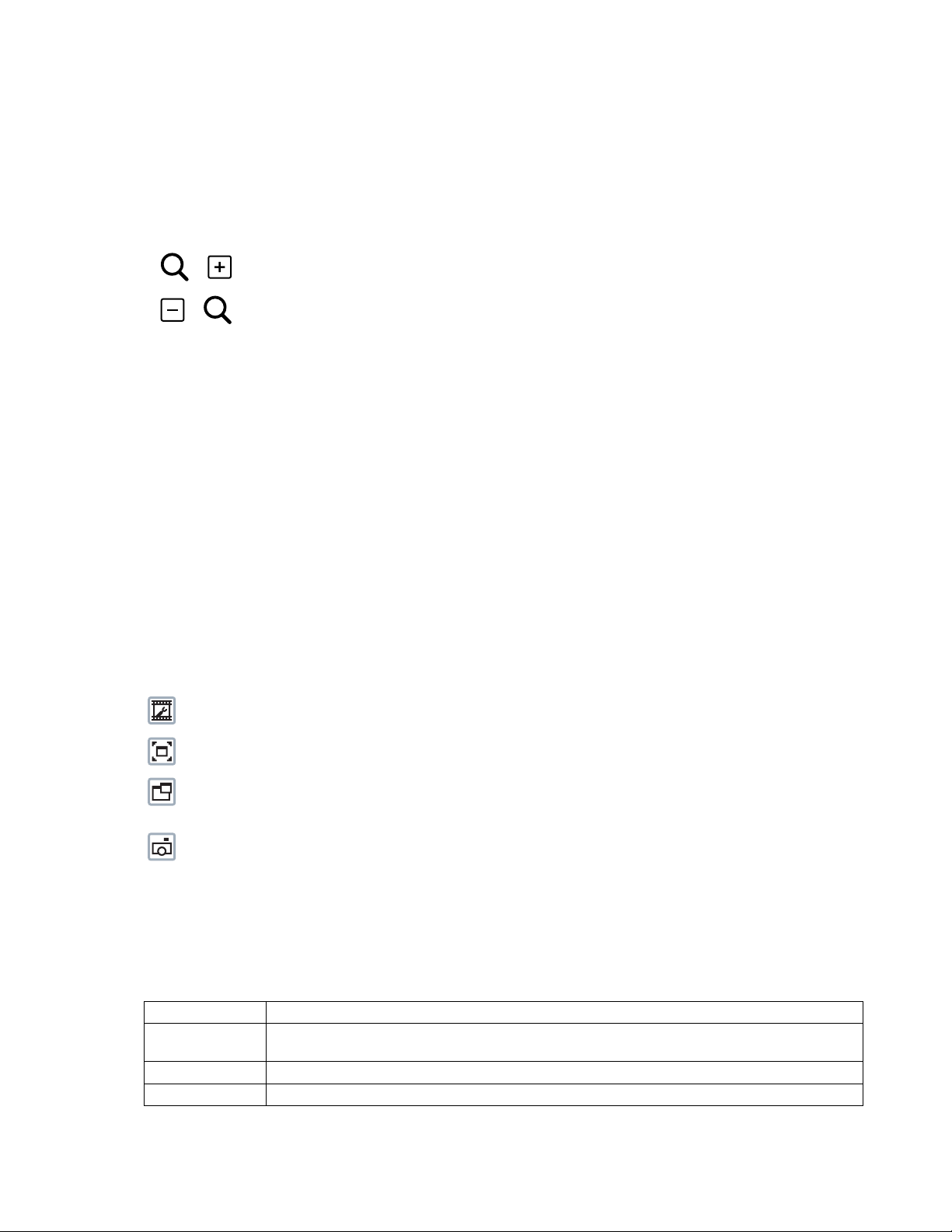
LIVE VIDEO PAGE ICONS
Viewable icons are based on user permissions.
Select Stream: Selects the viewable video stream that displays in live view (Primary, Secondary, QuickView, or Event) and selects
unicast or multicast and throttle settings.
Maximize Viewing Area: Scales the image to the full size of the browser. To resize the video pane to normal view, click the
Show Toolbar button in the upper-right corner of the window.
Open Stream in New Window: Opens the video in a scalable, independent window. Opening the video in a separate window allows
you to view the video while other applications are running. This window can be minimized, maximized, or closed using the title bar
buttons of the active window. The window can also be resized by dragging a corner of the window.
Take a Snapshot: Captures the image displayed in the video pane and saves it as a JPEG file.
KEYBOARD SHORTCUTS
Several keyboard shortcuts are available when viewing the primary stream on the live video page using Microsoft® Internet Explorer® and the
Pelco Media Player. These keyboard shortcuts display different overlays on a video pane and provide quick access to a specific function.
Table A. Keyboard Shortcuts
Keyboard Shortcut Function
SHIFT + A Displays analytics information for the currently active behavior. If there is no currently active behavior, this keyboard
shortcut has no effect.
SHIFT + S Displays details about the live video such as image rate, resolution, and bit rate.
SHIFT + T Displays the current date and time.
These keyboard shortcuts are not available when viewing video with Quicktime
8 C2270M (7/13)
®
.
Page 9

SELECTING A STREAM
1. Click the Select Stream button.
2. Select one of the following streams from the Select Stream page:
Primary Stream: To select this stream, click the button next to Primary Stream.
Secondary Stream: To select this stream, click the button next to Secondary Stream.
QuickView Stream: To select this stream, click the button next to QuickView Stream.
Event Stream: To select this stream, click the button next to Event Stream.
3. Configure the display settings for the selected stream. Available display settings are determined by the video compression of the selected
stream:
4. Click the Select button to save the stream settings.
PRIMARY STREAM AND SECONDARY STREAM
The Primary Stream and Secondary Stream are video streams that include compression, resolution, image rate, and bit rate settings. The streams
can be set up using a video configuration preset or they can be customized using the video configuration settings.
A video preset is a predefined video configuration that offers a good balance between video performance and bandwidth usage. For easy stream
configuration, use the Video Presets page located in the drop-down menu of the A/V Streams tab.
To customize the Primary Stream or Secondary Stream, select the Settings page and then use the Video Configuration page located in the dropdown menu of the A/V Streams tab. Configurable settings include the stream name, compression, resolution, image rate, bit rate, and I-frame
interval of the video streams. The default names for the streams are Primary Stream and Secondary Stream; however, if these stream names are
changed, the new names replace the default names (Primary Stream and Secondary Stream) on the Select Stream page.
QUICKVIEW STREAM
The QuickView Stream is a predefined JPEG video stream with a lower resolution. This low resolution, low frame rate stream is available when
the settings are being configured.
The QuickView Stream is also ideal for users who are connected to a network with processor bandwidth limitations that might cause a high
resolution, high frame rate video stream to pause or appear pixilated.
The aspect ratio of the QuickView Stream mirrors that of the Primary Stream.
EVENT STREAM
The Event Stream displays a list of alerts triggered by a running analytic behavior. The alert includes a screen capture, the profile that was
triggered, and the zone where the alert was detected. For the Event Stream to work you must have an analytic behavior profile running. To set up
and run analytic behaviors, profiles, and zones, use the Analytic Configuration page located in the drop-down menu of the Events tab.
UNICAST
A unicast transmission sends a separate video stream to each user that is requesting data. Although multiple users might request the same data
from the camera at the same time, duplicate video streams are transmitted to each user. Every unicast user that connects to the camera
consumes additional processing power, which limits the number of simultaneous users who can access the camera. The unicast transmission
setting is available in the primary and secondary stream display settings.
MULTICAST
A multicast transmission sends data to multiple users at the same time using one transmission stream. Each multicast user that connects to the
camera consumes no additional processing power; therefore, multicast video streams can be sent to an unlimited number of simultaneous users.
The multicast transmission setting is available in the primary and secondary stream display settings.
C2270M (7/13) 9
Page 10

THROTTLE
Throttle sets the upper limit on the image rate delivered to your computer. Lowering the throttle reduces the load on the network and on your
computer, which might be helpful when resources are limited. The throttle setting is available only when QuickStream is selected.
TAKING A SNAPSHOT
1. Click the Take a Snapshot button.
2. A dialog box opens, allowing you to open or save the file.
3. Select one of the following options:
Open: Your computer’s photo editing program opens and displays the screen image. This function is available only when using
Microsoft
Save: The image is saved as a JPEG file at the location you specify.
Cancel: The captured image is not opened or saved and the dialog box closes.
NOTE: The captured image resolution is 2016 x 1523 and is not dependent on the stream that is selected.
®
Internet Explorer® 7.0 (or later) or Mozilla® Firefox® 3.0 (or later).
Settings Page
Depending on user permissions, the Settings page allows you to manage camera system and network settings, set up users, configure events,
and control the camera imaging and streams.
NOTE: The Settings menu might not be available if the user does not have permission to access this feature.
ACCESSING THE CAMERA MENUS
1. Log on to the camera.
2. Click the Settings link in the navigation bar located in the upper-right corner of the page; a list of menu tabs appears.
3. Place your mouse pointer over a tab to display a list of submenus.
System Tab
Use the System tab to change general system settings, configure the time settings, set up the text overlay and image overlay for the live view,
install licenses, configure backup and restore, display system information, and access snapshots generated by event handlers.
General System Settings
The general system settings page includes configurable fields for the device name, time settings, text overlay, and image overlay. The device
name is the user-friendly description of the camera displayed in the gray area near the top of screen. The time server is an external server that
uses Network Time Protocol (NTP) to synchronize the camera date and time settings. The text overlay settings allow you to customize the
appearance of the video by displaying overlays such as the device name, or the date and time at the top or bottom of the video stream. The image
overlay settings allow you to customize the appearance of the video by displaying an image, such as a corporate logo, at the top or bottom of the
video stream.
You can also use the general system settings page to turn the camera’s LEDs on or off and to configure the Simple Mail Transfer Protocol (SMTP)
server to send an email notification when an event handler is activated.
NOTE: Contact your network administrator for information on configuring email notification on your local network.
You can also use the general system settings page to generate a system log, reboot the camera, or restore the camera’s factory default settings.
10 C2270M (7/13)
Page 11

Licensing Settings
The Licensing page provides an interface to add specialized features to your Sarix® device. Refer to license-specific documentation for more
information about installing licenses and the effects that a license might have on your device.
Backup and Restore Settings
The backup and restore settings page includes configurable fields for backup and restore of camera settings. Once the camera settings have
been configured for optimal scene display, use the backup feature to save the camera settings. If the camera settings are changed and
inadvertently result in a less desirable image, use the restore feature to restore the camera to the previously saved settings.
NOTE: This feature is not intended for the configuration of multiple units or for firmware upgrades.
Information Settings
The information settings page includes read-only fields for the firmware version, hardware version, model number, and serial number of the
camera. This information is typically required by Pelco Product Support for troubleshooting purposes.
Snapshot Viewer
The Snapshot Viewer page displays a list of snapshots saved to the SD card when a “Write JPEG to SD Card” event handler is activated. From
this page, you can open, download, or delete snapshots from the SD card. There are 100 snapshots displayed per page.
CHANGING THE DEVICE NAME
1. Place your mouse pointer over the System tab.
2. Select General Settings from the drop-down menu.
3. Click the Device Name box and highlight the text.
4. Type a user-friendly name into the Device Name box (2 to 63 characters). A user-friendly name makes it easier to recognize the device on
the network. Examples of user-friendly names are Front Door, Lobby, or Parking Lot.
5. Click Save to save the new device name, or click Reset to restore to the previously saved device name.
ENABLING LEDS
1. Place your mouse pointer over the System tab.
2. Select General Settings from the drop-down menu.
3. Select On or Off beside the Enable LEDs button to turn the camera’s power LED on or off. The default setting is Off for IME Series dome
cameras. The default setting is On for IXE Series box cameras.
4. Click Save to save the new setting, or click Reset to restore to the previously saved setting.
CONFIGURING SMTP SERVER
1. Place your mouse pointer over the System tab.
2. Select General Settings from the drop-down menu.
3. Click the SMTP Server box and type the address for the SMTP server used to deliver email from this camera's event system.
4. Click Save to save the new setting, or click Reset to restore to the previously saved setting.
C2270M (7/13) 11
Page 12

CONFIGURING TIME SERVER SETTINGS
Your device supports two methods for synchronizing with a time server: Auto and Manual. The Auto setting allows the device to discover and
synchronize with a network time server over IPv4 or IPv6. If a network time server is not available for discovery on the network, select the Manual
time server setting.
1. Place your mouse pointer over the System tab.
2. Select General Settings from the drop-down menu.
3. Select Auto or Manual for the Time Server. If you select Manual, provide the address or host name of the server.
4. Select the Time Zone.
NOTE: If your selected location observes daylight saving time (DST), the device with alutomatically change time on the associated dates.
5. Click the Save button to save the settings, or click the Reset button to clear all of the information you entered without saving it.
CUSTOMIZING THE APPEARANCE OF THE TEXT OVERLAY
1. Place your mouse pointer over the System tab.
2. Select General Settings from the drop-down menu.
3. Set the Text Overlay settings:
Date/Time Overlay: Select Show to display the date and time in the live view overlay. The default setting is Hide.
Camera Name Overlay: Select Show to display the camera name in the live view overlay. The default setting is Hide.
4. Select the display position for the overlay from the Position drop-down menu. Selections include Top Right, Top Center, Top Left, Bottom
Right, Bottom Center, and Bottom Left.
5. If an overlay is set to Show, view the format of the overlay in the Overlay Format area.
6. Click the Save button to save the settings, or click the Reset button to clear all of the information you entered without saving it.
CUSTOMIZING THE APPEARANCE OF THE IMAGE OVERLAY
1. Place your mouse pointer over the System tab.
2. Select General Settings from the drop-down menu.
3. Set the Image Overlay settings. Select Show to display the image overlay in the live view. The default setting is Hide.
4. Click Choose File and locate a portable pixel map (PPM) image for the overlay.
NOTE: PPM is the only image format that can be used in the image overlay. The PPM image must be a minimum resolution of 32 x 32 or a
maximum resolution of 256 x 192. GIF, JPEG, PNG and other formats are not recognized and cannot be uploaded. Free software
applications, such as GIMP, can be used to convert image formats to PPM.
5. Select the PPM image file to display in the live view overlay, and click Open.
6. Select the display position for the overlay from the Position drop-down menu. Selections include Top Right, Top Center, Top Left, Bottom
Right, Bottom Center, and Bottom Left.
7. Click the Save button to save the settings, or click the Reset button to clear all of the information you entered without saving it.
NOTE: The image overlay is not transparent and appears in front of most informational and text overlays and window blanking regions.
12 C2270M (7/13)
Page 13

GENERATING A SYSTEM LOG
1. Place your mouse pointer over the System tab.
2. Select General Settings from the drop-down menu.
3. Click the Generate System Log button.
4. A dialog box opens, allowing you to open or save the file.
5. Save the file to create a system log that can be used by Pelco Product Support for troubleshooting. Contact Pelco Product Support at
1-800-289-9100 (USA and Canada) or +1-559-292-1981 (international).
REBOOTING THE CAMERA
1. Place your mouse pointer over the System tab.
2. Select General Settings from the drop-down menu.
3. Click the Reboot Camera button to restart the camera.
NOTE: Rebooting the camera does not change the configured camera settings.
RESTORING ALL CAMERA DEFAULTS
WARNING: This process cannot be undone; all user and custom settings will be lost.
1. Place your mouse pointer over the System tab.
2. Select General Settings from the drop-down menu.
3. Click the Restore All Camera Defaults button to restore the camera’s factory default settings.
NOTE: If the device is not connected to a Dynamic Host Configuration Protocol (DHCP) network, the IP address settings for the device will be lost
and the server will not recognize the device. The default setting for the device IP address is DHCP On.
DOWNLOADING A FULL BACKUP OF CAMERA SETTINGS
1. Place your mouse pointer over the System tab.
2. Select Backup and Restore from the drop-down menu.
3. Click the Download Now button. A file download dialog box opens.
4. Click Save and specify where you want to save the file.
5. Click OK to save the backup file, or click Cancel to stop the operation.
C2270M (7/13) 13
Page 14

UPLOADING A BACKUP FILE TO RESTORE CAMERA SETTINGS
1. Place your mouse pointer over the System tab.
2. Select Backup and Restore from the drop-down menu.
3. Click the Browse button. A file upload dialog box opens.
4. Select the file you want to upload.
5. Click the Open button.
6. Click the Upload and Restore button.
NOTE: Restoring a backup file restarts the camera.
7. Click OK to restore the backup file, or click Cancel to stop the operation.
Network Tab
Use the Network tab to change the camera’s general network settings, select the Secure Sockets Layer (SSL) settings, enable Secure Shell (SSH),
configure 802.1x port security, and select Simple Network Management Protocol (SNMP) settings.
General Network Settings
The general network settings page includes configurable and read-only fields for IPv4 and IPv6 network communication settings. Available
settings include the hardware address, host name, IPv4 settings, and IPv6 settings. The hardware address is read-only.
IPv4 settings must be configured for the device. You can enable or disable the IPv4 DHCP setting from the general network settings page. If DHCP
is set to On, the IP address, subnet mask, gateway, and DNS server settings are automatically assigned to the device and are read-only text. If
DHCP is set to Off, these settings must be manually configured. The default camera setting for DHCP is On.
SSL Settings
The SSL settings page includes SSL configuration modes and certificate generation. To ensure security on the Internet, all Web browsers provide
several security levels that can be adjusted for sites that use SSL technology to transmit data. SSL encrypts communications, making it difficult
for unauthorized users to intercept and view user names and passwords.
SSL requires signed certificates to determine if the Web browser accessing the camera has the required authentication. The camera can
generate a certificate signing request (CSR) that can be sent to a certificate authority for a signature (for example, VeriSign
a self-signed certificate using the Generate Self-Signed Certificate option.
®
), or it can generate
SSH Settings
The SSH settings page enables or disables SSH access to the camera. SSH is a user-enabled protocol that allows Pelco Product Support to log on
to and service the camera for advanced troubleshooting purposes. From the SSH settings page, users with the appropriate permissions can
enable or disable SSH access to the camera.
802.1x Settings
The 802.1x settings page enables or disables 802.1x port security, which authenticates devices that want to establish a point-to-point access
through a wired or wireless port using Extensible Authentication Protocol (EAP) protocols. This port-based authentication method prevents
unauthorized access to a Local Area Network (LAN) through a physical port. For example, when a device is connected to a network port, the
network switch asks the device for authentication. The device replies with its credentials. If the credentials are accepted, the network switch
opens the port for normal use. If authentication fails, the device is prevented from accessing information on the port.
SNMP Settings
The SNMP setting page includes SNMP configuration settings. SNMP is an application layer protocol used to manage TCP/IP-based networks
from a single workstation or several workstations. The camera supports SNMP v2c and v3 and can be configured to send traps.
14 C2270M (7/13)
Page 15

CHANGING THE HOST NAME
1. Place your mouse pointer over the Network tab.
2. Select General from the drop-down menu.
3. View the read-only hardware address.
4. Click the Hostname box and highlight the text.
5. Type a user-friendly name into the Hostname box (1 to 21 characters) using alphanumeric characters. A user-friendly name makes it easier
to recognize the device on the network. Numeric-only names are not allowed.
6. Click the Save button to save the settings, or click the Reset button to clear all of the information you entered without saving it.
CHANGING THE HTTP PORT
NOTE: The HTTP port number must remain at the default setting of 80 when connecting to a Pelco video management system (VMS). If you are
connecting to a Pelco VMS, do not change the HTTP port setting.
1. Place your mouse pointer over the Network tab.
2. Select General from the drop-down menu.
3. Click the HTTP Port box and highlight the text.
4. Type a new port number for HTTP communications. The default setting is 80.
NOTE: Contact your network administrator before changing port settings to ensure they do not conflict with your network infrastructure.
5. Click the Save button to save the settings, or click the Reset button to clear all of the information you entered without saving it.
CHANGING THE HTTPS PORT
NOTE: Before configuring the HTTPS port, set the SSL configuration mode to either Optional or Required and install a security certificate.
1. Place your mouse pointer over the Network tab.
2. Select General from the drop-down menu.
3. Click the HTTPS Port box and highlight the text.
4. Type a new port number for HTTPS communications. The default setting is 443.
NOTE: Contact your network administrator before changing port settings to ensure they do not conflict with your network infrastructure.
5. Click the Save button to save the settings, or click the Reset button to clear all of the information you entered without saving it.
C2270M (7/13) 15
Page 16

CHANGING THE RTSP PORT
NOTE: The camera uses the RTSP protocol to communicate with a video management system (VMS). Do not change the RTSP port unless you
are sure your VMS does not use the default RTSP port.
1. Place your mouse pointer over the Network tab.
2. Select General from the drop-down menu.
3. Click the RTSP Port box and highlight the text.
4. Type a new port number for RTSP communications. The default setting is 554.
NOTE: Contact your network administrator before changing port settings to ensure they do not conflict with your network infrastructure.
5. Click the Save button to save the settings, or click the Reset button to clear all of the information you entered without saving it.
TURNING ON DHCP
The default Dynamic Host Configuration Protocol (DHCP) setting for the camera is DHCP On. If DHCP is set to Off, complete the following steps to
reset it to On.
1. Place your mouse pointer over the Network tab.
2. Select General from the drop-down menu.
3. Select On for DHCP.
4. Click the Save button to save the settings, or click the Reset button to clear all of the information you entered without saving it.
NOTE: If the camera is not connected to a DHCP server but DHCP is set to On, the default IP address 192.168.0.20 on subnet mask 255.255.255.0
is automatically assigned to the camera. After the first camera is connected and assigned the default IP address, the system automatically looks
for other cameras on the auto IP address system and assigns IP addresses in sequential order as required. For example, if three cameras are
connected to a network without a DHCP server, the first camera is assigned address 192.168.0.20, the second camera is assigned address
192.168.0.21, and the third camera is assigned address 192.168.0.22.
TURNING OFF DHCP
WARNING: Contact your network administrator to avoid any network conflicts before setting or changing the IP address of the device.
1. Place your mouse pointer over the Network tab.
2. Select General from the drop-down menu.
3. Select Off for the Dynamic Host Configuration Protocol (DHCP).
4. Change the following network settings as required:
IP Address: The address of the camera connected to the network.
Subnet Mask: The address that determines the IP network to which the camera is connected (relative to its address).
Gateway: The router that accesses other networks.
DNS Servers: The addresses of the dedicated servers that translate the names for Web sites and host names into numeric IP addresses.
5. Click the Save button to save the settings, or click the Reset button to clear all of the information you entered without saving it.
16 C2270M (7/13)
Page 17

CONFIGURING IPV6 SETTINGS
Your Sarix device supports IPv6 in conjunction with IPv4 configurations; the device does not support IPv6-only network deployments. The device
will accept up to sixteen IPv6 addresses, three IPv6 DNS servers, and three IPv6 gateways.
There are two configuration modes for IPv6 address assignments:
Auto: Enables automatic configuration using router advertisement. Additional configuration can be provided over DHCPv6 (if available on your
network). Selecting Auto mode still allows you to manually configure additional IPv6 addresses, DNS servers, and gateways.
Manual Only: Provides a link-local IPv6 address for the device and allows you to assign up to 16 static IPv6 addresses to the device.
1. Place your mouse pointer over the Network tab.
2. Select General from the drop-down menu.
3. Select On for IPv6.
4. Select a Configuration Mode from the drop-down box. Selecting Auto allows the device to configure the remaining IPv6 settings
automatically, rendering the remaining steps optional.
5. (Optional) Provide static, unicast addresses in the Manual IP Addresses box. Each address requires a prefix, and it must be input using the
format prefix/IPv6Address. Manual IP addresses without prefix information will be rejected.
6. (Optional) Provide the addresses of DNS servers that are not configured automatically in the Manual DNS Servers box.
7. (Optional) Provide the addresses of gateways that are not configured automatically in the Manual Gateways box.
NOTES:
• The device will not accept multicast, localhost, or undefined IPv6 addresses.
• Link-local addresses are not supported for DNS.
• Manually specified DNS servers supersede automatically discovered DNS servers.
• Manually specified DNS servers are not validated by the device; verify any manually specified DNS servers before saving IPv6 settings.
• Manually specified gateways must be on the same network as the devices’s IPv6 addresses. Behavior for a gateway that is not on the same
network as the device’s IPv6 addresses is undefined.
• Some video management systems (VMS), including Pelco VMS systems, do not support connections to cameras and encoders over IPv6.
C2270M (7/13) 17
Page 18

SELECTING THE SECURE SOCKETS LAYER MODE
1. Place your mouse pointer over the Network tab.
2. Select SSL from the drop-down menu.
3. Select one of the following modes:
Disabled: Turns off access to the Web client through SSL. Sensitive data is not encrypted during transmission. The default setting is
disabled.
NOTE: If the SSL mode is set to disabled, you cannot access the camera using a URL that begins with an “https:” protocol. Your Web
browser displays an error message if you do not type the camera URL correctly.
Optional: A signed SSL certificate must be installed, but a secure URL that begins with the protocol name “https:” is optional when
accessing the camera. You can also access the camera using a standard URL with the “http:” protocol, but sensitive data is not encrypted
during transmission. To ensure that sensitive data is encrypted, you must use a secure URL with the “https:” protocol.
Required: A signed Secure Sockets Layer (SSL) certificate must be installed, and a secure URL that begins with the protocol name “https:”
must be used to access the camera. Sensitive data is always encrypted during transmission. A URL that begins with the “http:” protocol
rather than the “https:” protocol is redirected to the secure URL automatically.
NOTE: Beginning with firmware version 1.8.2, this mode cannot be modified in the Web browser. To select or clear the Required mode, you
must use the ONVIF or Pelco API call. Doing so avoids placing the camera into a mode in which it would no longer work with a connected
VMS system.
GENERATING A SELF-SIGNED CERTIFICATE
1. Place your mouse pointer over the Network tab.
2. Select SSL from the drop-down menu.
3. Click the Install New Certificate button located at the bottom of the SSL Configuration page. The Select Certificate Install Method buttons
appear on the page.
4. Select Generate Self-signed Certificate and then click Next. The Generate Self-signed Certificate form opens.
5. Fill in all of the fields, and then click the Generate Certificate button.
6. After the certificate is uploaded to the device, select the desired mode.
7. Click the Save button to save the settings, or click the Reset button to clear all of the information you entered without saving it.
NOTE: Self-signed certificates are valid for one year. The certificate’s expiration date is listed in the “Valid from” and To fields in the Certificate
section of the window. If the certificate has expired and you attempt to access the camera using a secure URL, the Web browser displays a
message. Repeat this procedure to generate and upload a new certificate.
DELETING A SELF-SIGNED CERTIFICATE
1. Place your mouse pointer over the Network tab.
2. Select SSL from the drop-down menu.
3. Verify the certificate in the Certificate section of the window.
4. Click the Delete Certificate button.
5. Click the Save button to save the settings, or click the Reset button to clear all of the information you entered without saving it.
GENERATING A CERTIFICATE REQUEST
1. Place your mouse pointer over the Network tab.
2. Select SSL from the drop-down menu.
3. Click the Install New Certificate button located at the bottom of the SSL Configuration page. The Select Certificate Install Method buttons
appear on the page.
18 C2270M (7/13)
Page 19

4. Select Generate Certificate Request, and then click Next. The Generate Certificate Signing Request form opens.
5. Fill in all of the fields, and then click Generate Request. The following progress message appears on the page: “Generating certificate
signing request, please wait.”
6. Send the CSR, which looks like an encrypted block of undecipherable text, to a third-party certificate authority of your choice for a
signature. You will receive a signed certificate.
7. Click Choose File and browse to locate the certificate on your computer.
8. Click Open once you locate and select the certificate.
9. Click Upload Certificate to upload the signed certificate to the device.
10. After the certificate is uploaded, select the desired mode.
11. Click the Save button to save the settings, or click the Reset button to clear all of the information you entered without saving it.
NOTE: Depending on the third-party certificate authority that signed your certificate, you might need to renew your certificate after a specified
amount of time. Consult the certificate authority for more details.
ENABLING SECURE SHELL
1. Place your mouse pointer over the Network tab.
2. Select SSH from the drop-down menu.
3. Select the Enabled check box.
4. Click the Password box and type a password (4 to 16 alphanumeric characters). Passwords are case-sensitive.
NOTE: The default user name is “root” and cannot be changed. The user name and password are required when accessing the camera
through a third-party SSH client.
5. Click the Re-type Password box and retype your password.
6. Click the Save button to save the password and enable SSH, or click the Reset button to clear all of the information you entered without
saving it.
CONFIGURING THE 802.1X PORT SECURITY SETTINGS
WARNING: To prevent network conflicts, contact your network administrator before configuring the 802.1x port security settings.
1. Place your mouse pointer over the Network tab.
2. Select 802.1x from the drop-down menu.
3. Select On for the 802.1x port security. The default setting for 802.1x port security is Off.
4. Select the Extensible Authentication Protocol (EAP) method from the Protocol drop-down menu. Supported EAP methods include EAP-MD5,
EAP-TLS, EAP-TTLS, EAP-PEAP, and EAP-FAST.
5. Type the information required for the selected 802.1x EAP method.
6. Connect the PC to a 802.1x secured switch that has the same EAP method.
7. Click the Save button to save the settings, or click the Reset button to clear all of the information you entered without saving it.
C2270M (7/13) 19
Page 20

SELECTING SNMP SETTINGS
WARNING: The Simple Network Management Protocol (SNMP) settings are advanced controls. Contact your network administrator to
obtain the required information to configure SNMP settings.
1. Place your mouse pointer over the Network tab.
2. Select SNMP from the drop-down menu.
3. Select the SNMP version to configure: SNMP V2c or SNMP V3. The default setting is No SNMP Server, which disables the SNMP
configuration.
NOTE: SNMP V2c and SNMP V3 configuration settings are independent of each other, but only one SNMP version can be active at a time.
CONFIGURING SNMP V2C
1. Place your mouse pointer over the Network tab.
2. Select SNMP from the drop-down menu.
3. Select SNMP V2c for the SNMP version.
4. Type the community name in the Community String box. The default name for the Community String is ”public.”
5. Configure the Trap Configuration settings:
Address: Type the host name or IP address of the trap server.
Community String: Type the community name for the trap server.
6. Click the Save button to save the settings, or click the Reset button to clear all of the information you entered without saving it.
CONFIGURING SNMP V3
1. Place your mouse pointer over the Network tab.
2. Select SNMP from the drop-down menu.
3. Select SNMP V3 for the SNMP version.
4. Type the SNMP user name in the SNMP user box.
5. Select the encryption algorithm for authentication from the Authentication drop-down menu. Support authentication settings include None,
MD5, or SHA. If you use authentication method MD5 or SHA, type a password in the box to the right of the selected Authentication
encryption.
6. Select the privacy encryption algorithm setting from the Privacy drop-down menu. Supported encryption settings include None, DES, or
AES. If you use privacy method DES or AES, type a password in the Privacy text box.
7. Type the host name or IP address of the trap server in the Address box under Trap Configuration.
8. Click the Save button to save the settings, or click the Reset button to clear all of the information you entered without saving it.
20 C2270M (7/13)
Page 21

Imaging Tab
Use the Imaging tab to change the camera’s general image settings, adjust the camera exposure, program the focus mechanism, adjust the tone
map settings to increase scene detail, or define window blanking privacy areas.
General Imaging Settings
General imaging settings include adjustments for camera orientation and digital processing. The Orientation settings reconfigure the image
180 degrees horizontally and 180 degrees vertically. Use these settings when installing the camera in an inverted position. If the orientation is
not adjusted, the image will display upside down and mirrored.
Digital processing settings include 3D noise reduction and auto white balance options as well as slider controls to adjust the camera’s
sharpness, saturation, hue, contrast, brightness, and wide dyananic range (WDR) strength.
The WDR strength control offers a balance between image detail and image contrast. A lower WDR strength increases contrast in most scenes,
but with reduced detail. A higher WDR strength ensures greater detail, but may result in reduced contrast and a washed-out look to the image.
3D noise reduction reduces noise and creates the best image quality for most scenes, but can obscure details in moving objects. If moving
objects appear blurrier than the rest of the scene, turn 3D noise reduction off.
Auto white balance settings define how the camera processes video images to render true colors in a scene. When set to On, white balance
automatically adjusts to deliver the best possible image in scenes with changing lighting conditions or in scenes with more than one type of light
source. For example, scenes that benefit from white balance correction are outdoor scenes, indoor scenes that include a window or door that
opens to the outdoors, or indoor scenes that include both incandescent and fluorescent lighting.
Exposure Settings
The exposure settings page includes adjustments for exposure, flicker, and day and night options.
Exposure is the amount of light detected by the camera sensor. A scene with correct exposure settings has adequate detail and contrast between
white and dark values. An image with too little or too much exposure eliminates detail in the scene.
Flicker correction reduces rolling shutter flicker in images with reduced dynamic range. Auto flicker correction automatically reduces rolling
shutter flicker in scenes with reduced dynamic range, but it does not reduce picture flicker in scenes with high dynamic range. The On setting
reduces rolling shutter picture flicker, and it dramatically reduces the amount of dynamic range in the image. The default setting Off maintains
the maximum amount of dynamic range in the image, but it can produce rolling shutter picture flicker in scenes with florescent or other
oscillating light sources.
Day/night settings control the position of the IR cut filter, which determines the color or black-white setting of the camera. Day/night settings
change depending on the exposure settings.
Focus Settings
Focus sets the back focus to the center focal point of the scene. The camera can be configured to back focus automatically or manually. Auto
focus automatically back focuses the camera on the subject in the center of the scene. Manual focus turns off the auto focus mechanism and
locks the camera at a user-specified position. The manual focus setting is recommended only for indoor applications that have a single,
unchanging primary light source. The Focus page also includes Full Range Auto-Focus and Factory Defaults.
Tone Map Settings
Tone map balances the brightest and darkest sections of a scene to produce an image with more balanced lighting and more detail. This is
accomplished, in part, when the device maps the 10-bit input sensor data (0 to 1023 bits) into 8-bit output RGB values (0 to 255 bits).
Window Blanking Settings
Window blanking is used to conceal user-defined privacy areas. A blanked area appears on the screen as a solid gray window. The camera can
handle up to sixteen blanked windows as long as the total blanked area does not exceed 50 percent of the field of view.
C2270M (7/13) 21
Page 22

CONFIGURING THE ORIENTATION OF THE SCENE
1. Place your mouse pointer over the Imaging tab.
2. Select General from the drop-down menu.
3. Select one of the following options:
• Click the “Flip left-to-right” box to rotate the camera image 180 degrees horizontally.
• Click the “Flip top-to-bottom” box to rotate the camera image 180 degrees vertically.
CHANGING THE DIGITAL PROCESSING SETTINGS
1. Place your mouse pointer over the Imaging tab.
2. Select General from the drop-down menu.
3. Select 3D Noise Reduction:
Off: Turns noise reduction off. Video noise in low light is not reduced.
On: Selects a greater amount of video noise reduction in low light. The default setting is On.
NOTE: Turn off 3D noise reduction if details are blurred in moving objects.
4. Select Auto White Balance:
Off: Turns white balance off. Video noise in low light is not reduced.
On: Maintains automatic color balance for most lighting conditions, including environmental settings and scenes that do not change. The
default setting is On.
NOTE: If a temporary lighting condition causes poor Auto White Balance performance, the white balance can be locked in its current state
by turning the setting to Off.
5. Move the slider to the left or right to change the following settings:
Sharpness Adjust: Controls the clarity of detail in a scene. Move the slider to the right to increase the sharpness; move the slider to the
left to decrease the sharpness. Increasing the sharpness also increases the image noise. The range of adjustment is –100 to 100; the
default setting is 0 (zero).
Saturation Adjust: Controls how intense or vivid the colors are in a scene. Move the slider to the right to increase the saturation level;
move the slider to the left to decrease the saturation level. The range of adjustment is –100 to 100; the default setting is 0 (zero).
Hue Adjust: Controls the intensity of red or blue hues in a scene. The range of adjustment is –100 to 100; the default setting is 0 (zero).
Contrast Adjust: Controls gradations between the darkest and lightest portions of the scene. Move the slider to the right to increase the
contrast; move the slider to the left to decrease the contrast. The range of adjustment is –100 to 100; the default setting is 0 (zero).
Brightness Adjust: Controls the lighting detail in a scene. Move the slider to the right to lighten the image; move the slider to the left to
darken the image. The range of adjustment is –100 to 100; the default setting is 0 (zero).
WDR Strength: WDR balances the bright and dark parts of a scene. Move the slider to the right to darken the lighter parts of the scene;
move the slider to the left to lighten darker parts of the scene. The range of adjustment is –100 to 100; the default setting is 0(zero).
6. If required, click the Restore Settings to Defaults button to restore the default settings, or click the Restore All Imaging Settings button to
restore all the imaging settings.
22 C2270M (7/13)
Page 23

SELECTING EXPOSURE SETTINGS
1. Place your mouse pointer over the Imaging tab.
2. Select Exposure from the drop-down menu.
3. Set the exposure priority to Noise or Frame Rate. Exposure priority allows you to select the desired behavior when auto exposure settings
conflict with the desired frame rate selected on the stream configuration page.
Noise: This setting prioritizes the best image quality in all conditions regardless of your desired frame rate.
Frame Rate: This setting prioritizes a guaranteed frame rate in all lighting conditions.
4. Move the slider to the left or right to change the following settings:
Max Exposure Time: Controls the maximum time in milliseconds that the sensor is exposed to the light. Move the slider to the left to
decrease the maximum exposure time, which decreases light sensitivity and reduces motion blurring. Move the slider to the right to
increase the maximum exposure time, which increases light sensitivity and motion blurring. The available range of maximum exposure
settings is 1 to 500 msec; the default setting is 33.3 msec.
Max Gain: Increasing the gain increases the brightness of the image, but it also increases the amount of noise in the image. Move the
slider to the desired position. The available gain settings are 0 to 100. The default setting is 100.
5. Set the Flicker Correction mode to Auto, On, or Off.
Auto: This setting automatically reduces rolling shutter flicker in scenes with low dynamic range, but it does not reduce picture flicker in
scenes with high dynamic range.
On: This setting reduces rolling shutter picture flicker, and it dramatically reduces the amount of dynamic range in the image.
Off: This setting maintains the maximum amount of dynamic range in the image, but it can produce rolling shutter picture flicker in scenes
with florescent or other oscillating light sources. Off is the default setting.
6. If required, click the Restore Settings to Defaults button to restore the default settings.
DAY NIGHT SETTINGS
The Day Night mode controls the position of the IR cut filter, which determines the color or black-white setting of the camera. The Day Night
mode settings change depending on the Exposure settings. If the Day Night mode is set to Auto, the transition settings are available. If the
camera is set to Manual mode, the only available Day Night mode setting is Position, which sets the IR filter to either the day (color) position or
the night (black-white) position.
SELECTING DAY NIGHT AUTO MODE
1. Place your mouse pointer over the Imaging tab.
2. Select Exposure from the drop-down menu.
3. Select Auto for the Day Night mode. The auto setting automatically controls the IR cut filter depending on the Transition Level setting.
4. Set the transition level to the Lighter, Default, or Darker setting. The Transition Detect Time setting determines when the device changes
from day mode (color) to night mode (black-white).
5. Move the Transition Detect Time slider to the desired position. The Transition Detect Time setting determines the frequency at which the
device checks for sufficient ambient light to transition to day mode or night mode. Detection times are 0 to 60 sec.; the default setting is
5sec.
6. If required, click the Restore Settings to Defaults button to restore the default settings.
SELECTING DAY NIGHT MANUAL MODE
1. Place your mouse pointer over the Imaging tab.
2. Select Exposure from the drop-down menu.
C2270M (7/13) 23
Page 24

3. Select Manual for the Day Night mode. The manual mode sets the IR cut filter to a fixed position depending on the position setting.
Available settings include:
Day: Sets the IR filter to the day (color) position.
Night: Sets the IR filter to the night (black-white) position.
4. If required, click the Restore Settings to Defaults button to restore the default settings.
CONFIGURING AUTO FOCUS SETTINGS
1. Place your mouse pointer over the Imaging tab.
2. Select Focus from the drop-down menu.
3. Select the Auto mode.
4. Set the Temperature Change Refocus setting. The camera is programmed to run an automatic focus sequence when the internal
temperature sensor of the camera detects an environmental temperature change of 41°F (5°C). This focus sequence adjusts the center
focal point of the scene to maintain optimal focus. The default setting is On; select Off to turn off this setting.
5. Day/night cameras only: Set the Day/Night Switch Refocus setting. The default setting for the Day/Night Switch Refocus is Off. Select On
if the camera’s focal length is greater than ~25 mm or the night scene uses mostly IR lighting. The best method to determine if the day/night
refocus should be enabled is to test the camera with the daytime light conditions, and then test it again with the nighttime light conditions.
When the setting is On, the imager automatically refocuses the lens when the camera changes from night mode (black-white) to day mode
(color) or the reverse. For example, if the camera changes from day mode to night mode, the imager automatically adjusts the back focus for
the change in light.
6. If required, use one of the following buttons to adjust the focus:
Full Range Auto-Focus: The camera starts a full-range search to find the optimal focal point for the scene.
Restore Setings to Defaults: The camera resets the auto focus to the factory default setting.
CONFIGURING MANUAL FOCUS SETTINGS
NOTE: It is recommended to set the focus to Manual when using analytics. If the focus is set to Auto, significant background changes will occur
when the camera automatically adjusts to different points within a scene resulting in frequently changing image sharpness. This may cause
problems with scene recognition, which will suspend analytics operation or cause false alarms.
1. Place your mouse pointer over the Imaging tab.
2. Select Focus from the drop-down menu.
3. Select the Manual mode.
4. Set one of the following settings:
Day Manual Focus Position: (Available only with day/night cameras.) This is the position of the focus mechanism when the IR cut filter
is applied. The day mode focus position range is 0 to 100.
Night Manual Focus Position: (Available only with day/night cameras.) This is the position of the focus mechanism when the IR cut filter
is removed. The night mode focus position range is 0 to 100.
5. If required, click the Restore Settings to Defaults button to reset the focus to the factory default setting.
24 C2270M (7/13)
Page 25

SELECTING TONE MAP SETTINGS
1. Place your mouse pointer over the Imaging tab.
2. Select Tone Map from the drop-down menu.
3. Select the Optimization setting:
Normal (H.264): If the compression standard for the primary stream is H.264, set Optimization to Normal (H.264). This is the default
setting.
Photographic (JPEG): If the compression standard for the primary stream is JPEG, set Optimization to Photographic (JPEG).
4. Move the Tone Map sliders to adjust the following image settings:
Black Clip Percent: Adjusts the percent of pixels set to black. Move the slider to the right to darken the scene by increasing the number
of pixels that are mapped to absolute black. The black clip percent range is 0 to 5.0; the default setting is 1.0.
White Clip Percent: Adjusts the percent of pixels set to white. Move the slider to the right to lighten the scene by increasing the number
of pixels that are mapped to absolute white. The white clip range is 0 to 5.0; the default setting is 1.0.
5. If required, click the Restore Settings to Defaults button to restore the default settings.
TURNING ON WINDOW BLANKING
1. Place your mouse pointer over the Imaging tab.
2. Select Window Blanking from the drop-down menu.
3. Select On for Window Blanking.
4. In the Live Preview area of the page, click and drag the mouse diagonally across the area you want to blank. A color-coded box appears in
the Edit Window section of the page. The box is the same color as the window-blanking region drawn in the Live Preview area.
NOTE: Up to 16 window-blanking regions can be defined.
5. To resize the window, click and drag one or more of the points until the window is the desired shape and size.
NOTE: Window-blanking regions will not scale proportionally with changes in zoom. Set the zoom level for the camera before defining
window-blanking regions.
6. Click the Save button to save the settings, or click the Reset button to clear all of the information you entered without saving it.
TURNING OFF WINDOW BLANKING
1. Place your mouse pointer over the Imaging tab.
2. Select Window Blanking from the drop-down menu.
3. Select Off for Window Blanking.
4. Click the Save button to save the settings, or click the Reset button to clear all of the information you entered without saving it.
C2270M (7/13) 25
Page 26

DELETING A WINDOW BLANKING AREA
1. Place your mouse pointer over the Imaging tab.
2. Select Window Blanking from the drop-down menu.
3. In the Edit Window area of the page, click the Delete button “X” next to the window blanking area you want to delete.
4. Click the Save button to save the settings, or click the Reset button to clear all of the information you entered without saving it.
RESTORING WINDOW BLANKING DEFAULTS
1. Place your mouse pointer over the Imaging tab.
2. Select Window Blanking from the drop-down menu.
3. Click the Restore Settings to Defaults button. All defined windows are deleted, and the Window Blanking settings are restored to the
default settings of Off.
A/V Streams Tab
Use the A/V Streams tab to configure the video and audio streams for the camera. The A/V Streams tab includes video presets settings, and
video and audio configuration.
Video Presets Settings
The video preset settings page includes three fully-configured video presets, High, Medium, and Low, which include primary and secondary video
stream settings for easy setup. These presets can also be used as a starting point for a custom video configuration. These preset configurations
vary depending on camera model.
Video Configuration Settings
The video configuration settings page allows you to customize the compression, resolution, image rate, bit rate, and I-frame interval of the video
streams. The default names for the streams are Primary Stream and Secondary Stream. Although each stream can be configured independently,
the settings of one stream can limit the options available to the other stream, depending on the processing power used.
NOTE: Always configure the primary stream before the secondary stream. The primary stream should always be the most resource-intensive of
the streams.
Audio Configuration Settings
The audio configuration settings page allows you to set up the internal audio device or an external audio device. The default setting for audio is
disabled, which means that no audio is transmitted from the camera. When enabled, audio is transmitted from the camera to the PC. Based on
your system configuration, images and audio might not be synchronized.
Not all camera models are equipped with an internal audio device. Refer to the specifications for your camera model for information.
NOTE: Improper use of audio/visual recording equipment might subject you to civil and criminal penalties. Applicable laws regarding the use of
such capabilities vary between jurisdictions and might require, among other things, express written consent from the recorded subjects. You are
solely responsible for ensuring strict compliance with such laws and for strict adherence to any/all rights of privacy and personalty.
SELECTING A VIDEO PRESET CONFIGURATION
1. Place your mouse pointer over the A/V Streams tab.
2. Select Video Presets from the drop-down menu.
3. Click the button next to the desired video preset stream configuration.
4. Click the Save button to save the settings, or click the Reset button to clear your selection without saving it.
26 C2270M (7/13)
Page 27

CONFIGURING A CUSTOM VIDEO STREAM CONFIGURATION
1. Place your mouse pointer over the A/V Streams tab.
2. Select Video Configuration from the drop-down menu.
3. Click both of the Clear buttons to delete the primary and secondary streams settings.
4. Optional: In the Primary Stream section, type a user-friendly name in the Name box (2 to 64 characters). A user-friendly name makes it
easier to recognize the stream (for example, Live and Recording).
5. Configure the Compression Standard, Resolution, Image Rate, Bit Rate, and I-frame Interval settings for the primary stream.
NOTE: The compression standard, resolution, image rate, bit rate, and I-frame interval settings are dependent on each other. You must first
decide the priority setting before you configure a stream. For example, if you want an image rate of 30 ips, set the image rate before you
configure the other settings.
6. For the H.264 compression standard, configure the additional QoS (DSCP) Codepoint, Endura Signing, Profile, and Rate Control settings.
7. Repeat steps 3 to 6 for the Secondary stream.
8. Click the Save button to save the settings, or click the Reset button to clear all of the information you entered without saving it.
COMPRESSION STANDARDS
JPEG: A commonly used video compression scheme. JPEG has the least impact on the camera’s processor, but it requires the most bandwidth.
MJPEG: Motion JPEG has the same characteristics as JPEG but differs in its mode of transfer (RTP).
H.264: Also known as MPEG-4 Part 10 or Advanced Video Coding (AVC), H.264 is one of the most widely used compression, recording, and
distribution methodologies for High Definition (HD) video. It is used in Blu-ray™ video players and by companies that transmit HD video or movies
over the internet and by satellite. H.264 is the most processor-intensive compression standard, but it requires the least amount of bandwidth.
RESOLUTION AND RECOMMENDED BIT AND IMAGE RATES
Refer to the following table for the resolution capabilities, recommended bit rates, and maximum image rates of your camera model.
Table B. Camera Resolutions and Bit and Image Rates
Resolution JPEG H.264 High Profile
Camera Model
3 MPx 3.0 2048 1536 4:3 7 12 30 9.2
2 MPx 1.9 1600 1200 4:3 15 12 30 5.7
1 MPx 1.2 1280 960 4:3 30 12 30 3.8
0.5 MPx 0.5 800 608 4:3 30 7.8 30 2
3 MPx and 2 MPx 1080p 1920 1080 16:9 15 12 30 6
1 MPx 720p 1280 720 16:9 30 12 30 2.9
0.5 MPx 0.5 800 448 16:9 30 5.7 30 1.7
MPx Width Height
0.3 640 480 4:3 30 4.9 30 1.5
0.08 320 240 4:3 30 1.2 30 0.5
0.2 640 352 16:9 30 3.6 30 1.2
0.06 320 176 16:9 30 0.9 30 0.4
Aspect
Ratio
IPS
(Max.)
Recommended
Bit Rate
IPS
(Max.)
Recommended
Bit Rate
IMAGE RATE
The image rate is the number of images per second (ips) available for the video stream configuration. Available image rates depend upon the
model of the device that you are using.
NOTE: The maximum image rate setting might not be obtainable due to the compression standard and the resolution of the stream.
C2270M (7/13) 27
Page 28

BIT RATE
The bit rate is the quality of the video stream (rendered in kilobits per second). The higher the value, the higher the video quality and bandwidth
required.
NOTE: When you change any of the video stream configuration settings, the camera automatically adjusts the bit rate. If you manually reduce
the bit rate lower than the camera's automatic setting, the image quality might be reduced and the stream selection options might be limited.
I-FRAME INTERVAL
The I-frame interval configures the number of partial frames that occur between full frames in the video stream. For example, in a scene where a
door opens and a person walks through, only the movements of the door and the person are stored by the video encoder. The stationary
background that occurs in the previous partial frames is not encoded, because no changes occurred in that part of the scene. The stationary
background is only encoded in the full frames. Partial frames improve video compression rates by reducing the size of the video. As the I-frame
interval increases, the number of partial frames increases between full frames. Higher values are recommended only on networks with high
reliability. This setting is available only with H.264.
QUALITY OF SERVICE FOR DIFFERENTIATED SERVICES CODE POINT
Quality of Service (QoS) for Differentiated Services Code Point (DSCP) is a code that allows the network to prioritize the transmission of different
types of data. This setting is available only with H.264.
NOTES:
• If you are not familiar with DSCP, contact your network administrator before changing this setting.
• Your network must be configured to use QoS. If you are unsure if your network is QoS-aware, contact your network administrator.
ENDURA SIGNING
Enabling the Endura Signing feature allows an Endura® system to authenticate video from an Endura recorded stream. This setting is available
only with H.264.
PROFILE
The profile defines the subset of bit stream features in an H.264 stream, which includes color reproduction and additional video compression. It
is important to select the highest profile that is compatible with the recording device so that you receive the best compression that your decoder
can process.
Baseline: A simple profile with a low compression ratio. A baseline profile is compatible with more recorders but uses more bits to compress
quality video than the other profiles. This profile supports I-frames and P-frames. Use the baseline profile in applications with limited scene
changes; for example, an indoor scene with a single, unchanging primary light source and minimal motion.
Main: An intermediate profile with a medium compression ratio. The default setting is main. This profile is compatible with most recorders and
uses fewer bits to compress video than the baseline profile; however, it uses more bits than the high profile. The main profile supports I-frames
and P-frames.
High: A complex profile with a high compression ratio. This is the primary profile for high-definition television applications; for example this is
the profile adopted for Blu-ray and HD-DVD. The high profile supports I-frames and P-frames.
RATE CONTROL
The rate control setting determines the bit rate and quality of each frame in the H.264 video stream. Each rate control setting is a compromise
between image quality and the resources required for video storage.
CBR: The constant bit rate (CBR) streams video at a fixed number of bits per second. CBR uses the full capacity of the bit rate setting for scenes
with or without motion. Video is always streamed at the user bit rate setting.
VBR: The variable bit rate (VBR) reduces or increases bit rates in response to motion while maintaining high-quality video. VBR uses variable
capacity of the bit rate setting for scenes according to a user-defined target bit rate.
CVBR: The constrained variable bit rate (CVBR) provides high-quality video and long recording time of variable bit rate while limiting variations
in recording capacity consumption.
28 C2270M (7/13)
Page 29

SELECTING AUDIO CONFIGURATION SETTINGS
To use audio with the camera if it does not have built-in audio support, you must connect an audio device to the accessory port. Once the device
is connected, audio can only be enabled through the primary stream.
Audio and video may not be synchronized when viewing and listening to the primary stream through a Web browser. You may experience a
three-second delay in video when viewing the primary stream with audio.
NOTE: Improper use of audio/visual recording equipment may subject you to civil and criminal penalties. Applicable laws regarding the use of
such capabilities vary between jurisdictions and may require, among other things, express written consent from the recorded subjects. You are
solely responsible for ensuring strict compliance with such laws and for strict adherence to any/all rights of privacy and personalty.
1. Place your mouse pointer over the A/V Streams tab.
2. Select Audio Configuration from the drop-down menu.
3. Select Enabled in the Audio section.
4. Select the audio device setting from the Audio Device drop-down box.
Native Line In: (Only available with specific Sarix technology products that have built-in audio. Refer to the specifications for your product
model for information.) Enables audio from a microphone connected to the audio-in connector.
Native Microphone In: (Only available with specific Sarix technology products that have built-in audio. Refer to the specifications for
your product model for information.) Enables audio from the internal microphone.
5. Select the sample rate from the Sample Rate drop-down box. The sample rate is the quality of the audio stream (rendered in hertz per
second). The higher the value, the higher the audio quality. Available sample rate settings are 8000 and 12000 Hz. The default setting is
8000 Hz.
6. Select the encoding method for the audio device from the Encoding drop-down box. Available encoding methods are PCMU, PCMA, and
PCM16. The default setting is PCMU.
7. Click the button next to Echo Cancellation (Enabled or Disabled) that you want to select.
8. If required, click the button next to Mute to mute the audio device.
NOTE: Do not use the mute button on an audio device, as it will override the audio software settings. To mute the audio device, select
Mute located on the Audio Configuration page.
9. Set the sensitivity of the input level by moving the Input Level slider. Move the slider to the right to increase the sensitivity level; move it to
the left to decrease the sensitivity level. For example, if the camera is installed in a noisy environment or the connected microphone has a
built-in line amplifier, set the sensitivity to a low setting. The setting range is 0 to 100.
10. Click the Save button to save the settings, or click the Reset button to clear all of the information you entered without saving it.
C2270M (7/13) 29
Page 30

Users Tab
Use the Users tab to create and manage user accounts and to change the way the camera manages the users settings.
General Users Settings
The general users settings page sets the open or closed authentication mode. With open authentication, users can view video and use the
camera API without validating user credentials. With closed authentication, users must log on to the camera with a user name and password.
The general users settings page also allows you to change the way the camera manages users and groups. These settings can be managed on a
camera-to-camera basis (local mode) or by using a centralized server to apply changes to multiple cameras (remote mode).
Users Settings
The users settings page defines the access levels assigned to individuals logged on to the camera. Use this page to create, modify, or delete user
accounts for Administrators, Managers, Operators, and Viewers. User accounts are created to limit permissions.
SELECTING THE USERS AND GROUPS SETTINGS
1. Place your mouse pointer over the Users tab.
2. Select General Settings from the drop-down menu.
3. Select one of the following Authentication modes:
Open Authentication: Allows users to view video and use the camera API without validating user credentials. When Open Authentication
is selected, you can select “Require password for PTZ control” to limit PTZ control to authenticated users.
Closed Authentication: Requires users to possess valid credentials to view video and access the camera API. Before selecting Closed
Authentication, ensure that your video management system supports Closed Authentication mode.
4. Select one of the following User and Group Management modes to manage permissions of users and groups:
Local Mode: The camera manages users and groups locally. Any changes to users and groups affect only the camera that you are
accessing. The default setting is Local Mode.
Remote Mode: The camera authenticates and manages users through a Lightweight Directory Access Protocol (LDAP) server supported by
Microsoft
Selecting Remote Mode disables Local Mode and all management is done on the server.
5. Click the Save button to save the settings, or click the Reset button to clear all of the information you entered without saving it.
®
Active Directory®. This allows administrators to tie cameras and group permissions into existing single sign-on services (SSO).
WARNING: Remote Mode settings are advanced controls. Contact your network administrator to obtain the required information to
configure remote settings.
30 C2270M (7/13)
Page 31

ENABLING REMOTE MODE
1. Place your mouse pointer over the Users tab.
2. Select General Settings from the drop-down menu.
3. Select Remote Mode. The default setting is Local Mode.
4. Type the IP address or host name of the LDAP server in the LDAP Server box.
5. Type the port over which the camera communicates with the LDAP server in the LDAP Port box. The default port for LDAP communications
is 389.
6. Type the distinguished name (DN) or domain component (DC) that is the basis for LDAP searches in the Base DN box.
7. Provide the template to format the user name (provided when the user logs on to the camera) for searches in the LDAP directory in the Bind
DN Template box.
8. Provide the LDAP search query for users found in the base DN in the Search Template box. The search must match an entry in the LDAP user
record to the bind name (user name).
9. Type the Group Mappings for each of the camera’s four user groups:
a. Type the common name (CN) and domain component (DC) for the group of users to whom you want to grant admin access in the
Admins box.
b. Type the CN and domain component (DC) for the group of users to whom you want to grant manager access in the Managers box.
c. Type the CN and domain component (DC) for the group of users to whom you want to grant operator access in the Operators box.
d. Type the CN and domain component (DC) for the group of users to whom you want to grant viewer access in the Viewers box.
10. Type the credentials of a user who can be authenticated through the LDAP server in the User and Password boxes.
NOTE: Remote Mode (LDAP authentication) will not be enabled if you leave these boxes blank or do not provide valid credentials; this
ensures that you cannot lock yourself out of the camera with invalid or incorrect LDAP settings.
11. Click the Save button to save the settings, or click the Reset button to clear all of the information you entered without saving it.
CREATING A NEW USER
1. Place your mouse pointer over the Users tab.
2. Select Users from the drop-down menu.
3. Select the Access Level for the user:
Admins: Permissions include access to all camera settings.
Managers: Permissions include access to all settings except this user cannot modify user permissions or restore factory default settings.
Operators: Permissions include view video, use PTZ functions, and use the API.
Viewers: Permissions include view video and use the API.
4. Click the Username box and type a user name (2 to 32 alphanumeric characters). User names are not case-sensitive and are saved in
lowercase characters.
5. Click the Password box and type a password (4 to 64 alphanumeric characters). Passwords are case-sensitive.
6. Click the Retype Password box and retype your password.
7. Click the Save button to save the settings and create a new user (the new user profile appears in the Users box on the left side of the page),
or click the Reset button to clear all of the information you entered without saving it.
C2270M (7/13) 31
Page 32

EDITING A USER
1. Place your mouse pointer over the Users tab.
2. Select Users from the drop-down menu.
3. Click the user profile that you want to edit from the Users box on the left side of the page.
4. If required, select a different Access Level for the user.
5. Double-click each of the password boxes to highlight the text. Type the new information in each password box.
NOTE: The Username cannot be modified; this box is read-only.
6. Click the Save button to save the settings, or click the Reset button to clear all of the information you entered without saving it.
DELETING A USER
1. Place your mouse pointer over the Users tab.
2. Select Users from the drop-down menu.
3. Click the user profile that you want to delete from the Users box located on the left side of the page.
4. Click the Delete User button. A dialog box opens and the following message appears “Are you sure you want to delete this user?”
5. Click OK. The user profile is deleted from the Users box.
NOTE: The “admin” user cannot be deleted.
32 C2270M (7/13)
Page 33

Events Tab
Use the Events tab to configure camera events and analytics.
Events are activated by user-defined event sources that tell the device how to react when an event occurs. Event handlers are the actions that
the device takes when an event occurs. For example, a system source can be configured to send email to an operator if the system shuts-down
and restarts.
Sources Settings
The sources settings page defines the camera functions that are automatically triggered by an event source. The camera supports Alarm,
Analytics, System, and Timer sources. The Alarm source is the camera input for an external signaling device, such as a door contact or motion
detector. The Analytics source triggers when any configured behavior is detected. The System source is activated when the camera restarts. The
Timer source is a user-defined event that activates an event after a specified amount of time.
Handlers Settings
The handlers settings page defines the actions that a camera takes when an event occurs. The camera supports Send Email, Write JPEG to
SD Card, Upload JPEG to FTP Server, and Open/Close Relay handlers. The Send Email handler sends an email to a defined email address when an
event is activated. The Write JPEG to SD Card handler saves a JPEG of the activated event to an SD card. The Upload JPEG to FTP Server handler
saves a JPEG of the activated event to a defined FTP server. The Open/Close Relay handler sends a signal to an external device when an alarm or
relay is triggered.
NOTE: The Pelco Alarm accessory must be connected to the camera’s accessory port for Open/Close Relay to work.
Analytic Configuration Settings
The analytic configuration settings page includes behaviors for which you can create custom profiles that contain different camera settings. With
these profiles, you can set up different scenarios for the behavior that automatically detects and triggers alarms when the specific activity is
detected.
Pelco analytics can be configured and enabled using a standard Web browser. The device is preloaded with user-configurable behaviors and is
capable of running several behaviors at the same time. The number of behaviors is limited to the available processing power of the device.
Available processing power is determined by the settings for compression standards, resolution, image rate, bit rate, and analytic configuration.
Pelco analytics are also compatible with Endura® or a third-party system that supports alarms using Pelco’s API. Refer to the specific product
documentation for instructions on how to configure and enable Pelco analytics.
NOTE: Analytic alerts can be seen in the event stream, but alarms are only transmitted through Pelco’s API.
Pelco analytics include the following behaviors:
Adaptive Motion: Detects and tracks objects that enter a scene and then triggers an alarm when the objects enter a user-defined zone. The
objects are monitored until they exit the scene.
Camera Sabotage: Detects contrast changes in the field of view. An alarm is triggered if the lens is obstructed with spray paint, a cloth, or
covered with a lens cap. Any unauthorized repositioning of the camera also triggers an alarm.
C2270M (7/13) 33
Page 34

SOURCES
An event is a preconfigured camera function that is activated automatically by an event source. The camera supports the following types of event
sources:
Alarm: An alarm source is an input for external signaling devices, such as door contacts or motion detectors. If the Pelco Alarm accessory is
connected to the device’s accessory port, the device can support four alarm sources.
Analytics: An analytic source will activate a user-defined event handler when an analytic alert is detected.
System: A system source activates a user-defined event handler when the camera restarts.
Tim er: A timer source activates a user-defined event handler after a specified amount of time.
CREATING AN ALARM EVENT SOURCE
1. Place your mouse pointer over the Events tab.
2. Select Sources from the drop-down menu.
3. In the New Event Source section of the window, click the Name box and type a user-friendly name (2 to 23 alphanumeric characters).
4. Select Alarm from the Type drop-down menu.
5. Select PCP2 from the Alarm Bank drop-down menu.
6. Select the alarm you want to trigger when an event occurs from the Alarm drop-down menu.
7. Move the Dwell Time slider to set the amount of time in seconds that the alarm is active. The dwell time range is 0.1 to 25 seconds;
the default setting is 0.1.
8. Select either Normally Open or Normally Closed from the Polarity drop-down menu.
9. Select either True or False from the Supervised drop-down menu.
10. Click the Submit button to save the settings, or click the Reset button to clear all of the information you entered without saving it.
CREATING AN ANALYTICS EVENT SOURCE
1. Place your mouse pointer over the Events tab.
2. Select Sources from the drop-down menu.
3. In the New Event Source section of the window, click the Name box and type a user-friendly name (2 to 23 alphanumeric characters).
4. Select Analytics from the Type drop-down menu.
5. Select the Any Analytics check box to activate an event when any analytic event occurs.
6. Click the Submit button to save the settings, or click the Reset button to clear all of the information you entered without saving it.
CREATING A SYSTEM EVENT SOURCE
1. Place your mouse pointer over the Events tab.
2. Select Sources from the drop-down menu.
3. In the New Event Source section of the window, click the Name box and type a user-friendly name (2 to 23 alphanumeric characters).
4. Select System from the Type drop-down menu.
5. Select the Boot check box to activate an event when the camera reboots.
6. Click the Submit button to save the settings, or click the Reset button to clear all of the information you entered without saving it.
34 C2270M (7/13)
Page 35

CREATING A TIMER EVENT SOURCE
1. Place your mouse pointer over the Events tab.
2. Select Sources from the drop-down menu.
3. In the New Event Source section of the window, click the Name box and type a user-friendly name (2 to 23 alphanumeric characters).
4. Select Timer from the Type drop-down menu.
5. Configure the frequency:
a. Select the time interval from the drop-down menu. Time intervals include seconds, minutes, hours, or days. The default setting is
seconds.
b. Click the Frequency box and type a number.
6. Click the Submit button to save the settings, or click the Reset button to clear all of the information you entered without saving it.
EDITING AN EVENT SOURCE
1. Place your mouse pointer over the Events tab.
2. Select Sources from the drop-down menu.
3. Click the source profile that you want to edit from the Sources box located on the left side of the page.
4. Make your changes to the available fields in the Edit Event Source section of the window.
5. Click the Submit button to save the settings, or click the Reset button to clear all of the information you entered without saving it.
DELETING AN EVENT SOURCE
1. Place your mouse pointer over the Events tab.
2. Select Sources from the drop-down menu.
3. Click the source profile that you want to delete from the Sources box located on the left side of the page.
4. Click the Delete Source button. The source profile is deleted from the Sources box.
C2270M (7/13) 35
Page 36

HANDLERS
Event handlers are the actions that the camera takes when an event occurs. The camera supports the following event handlers:
Send Email: Sends an email to a defined email address when an event is activated. The Simple Mail Transfer Protocol (SMTP) server must be
configured to accept the camera’s IP address.
Write JPEG to SD Card: Saves a JPEG of the activated event to an SD card. An SD card must be installed in the device for this handler to
function.
NOTE: The SD card must be formatted as FAT32. Other formats are not compatible with the camera.
Upload JPEG to FTP Server: Saves a JPEG of the activated event to a defined FTP server.
Open/Close Relay: Sends a signal to an external device when an alarm or relay is triggered.
CREATING AN EVENT HANDLER: SEND EMAIL
NOTE: To use email notification, the camera must be connected to a local area network (LAN) that maintains an SMTP mail server. Contact your
network administrator for information on configuring email notification on your local network.
1. Configure the SMTP server to send email.
2. Place your mouse pointer over the Events tab.
3. Select Handlers from the drop-down menu.
4. In the New Event Handler section of the window, click the Name box and type a user-friendly name (2 to 23 alphanumeric characters).
5. Select Send Email from the Type drop-down menu.
6. Click the boxes (To, From, Subject, and Message), and then type the necessary information in each box.
7. Select the JPEG Snapshot box if you want to send a JPEG as an attachment.
8. Select the Attach Raw Event Data box if you want the email to include extra data about the event. For example, select this box if the event
is triggered by an alarm and you want to receive data about the state, time, or type of alarm.
9. If you do not want the handler to activate every time an event occurs, set filters for the handler:
a. Select the day(s) of the week on which you want emails to be sent.
b. Type times in the Start and End boxes for the days you have selected. Use time values in 24-hour notation (for example, use 0800 for
8:00 a.m., 1600 for 4:00 p.m.).
c. If required, click the plus button (+) to add another time range.
10. Select one or more event sources to send an email when those event sources are activated.
11. Click the Submit button to save the settings, or click the Reset button to clear all of the information you entered without saving it.
CREATING AN EVENT HANDLER: WRITE JPEG TO SD CARD
1. Install an SD card in the SD card slot located on the back of the camera.
NOTE: The SD card must be formatted as FAT32. Other formats are not compatible with the camera.
2. Place your mouse pointer over the Events tab.
3. Select Handlers from the drop-down menu.
4. Click in the Name box and type a user-friendly name (2 to 23 alphanumeric characters).
5. Select the Write JPEG to SD Card option from the Type drop-down menu.
6. The JPEG files saved to the SD card will be given file names that correspond to the date and time of the event. Select a time standard from
the File Name drop-down menu.
7. Click in the Size limit box and type a number. Select Kilobytes, Megabytes, or Gigabytes from the Size Limit drop-down menu.
36 C2270M (7/13)
Page 37

NOTE: Do not select a size limit that is larger than the amount of memory on the SD card. For example, if the SD card is 2 MB, do not
exceed 2 MB in the Size Limit box.
8. If you do not want the handler to activate every time an event occurs, set filters for the handler.
a. Select the day(s) of the week on which you want JPEGs saved to the SD card.
b. Type times in the Start and End boxes for the days you have selected. Use time values in 24-hour notation (for example, use 0800 for
8:00 a.m., 1600 for 4:00 p.m.).
9. Select one or more sources to save a JPEG to the SD card when those event sources are activated.
10. Click the Submit button to save the settings, or click the Reset button to clear all of the information you entered without saving it.
CREATING AN EVENT HANDLER: UPLOAD JPEG TO FTP SERVER
1. Place your mouse pointer over the Events tab.
2. Select Handlers from the drop-down menu.
3. In the New Event Handler section of the window, click the Name box and type a user-friendly name (2 to 23 alphanumeric characters).
4. Select the Upload JPEG to FTP Server option from the Type drop-down menu.
5. Click the Server box and type the server address (1 to 32 alphanumeric characters).
6. Click the Username box and type the user’s name (1 to 32 alphanumeric characters).
7. Click the Password box and type a password (4 to 16 alphanumeric characters).
8. Click the Base Path box and type the base path (1 to 32 alphanumeric characters). The base path is the path to your root directory.
9. Select a time standard from the File Name drop-down menu. The JPEG files uploaded to the FTP server are given file names that
correspond to the date and time of the event.
10. If you do not want the handler to activate every time an event occurs, set filters for the handler:
a. Select the day(s) of the week on which you want JPEGs saved to the FTP server.
b. Type times in the Start and End boxes for the days you have selected. Use time values in 24-hour notation (for example, use 0800 for
8:00 a.m., 1600 for 4:00 p.m.).
c. If required, click the plus button (+) to add another time range.
11. Select one or more sources to save a JPEG to the FTP server when those event sources are activated.
12. Click the Submit button to save the settings, or click the Reset button to clear all of the information you entered without saving it.
CREATING AN EVENT HANDLER: OPEN CLOSE RELAY
1. Place your mouse pointer over the Events tab.
2. Select Handlers from the drop-down menu.
3. In the New Event Handler section of the window, click the Name box and type a user-friendly name (2 to 23 alphanumeric characters).
4. Select Open/Close Relay in the Type drop-down menu.
5. Select the serial number of the relay device from the Relay Bank drop-down menu.
6. Select the relay you want to trigger when an event occurs from the Relay drop-down menu.
7. Move the On Time slider to set the amount of time for the relay to remain open. The time range is 0.1 to 200 seconds; the default setting
is 0.1.
8. Move the Off Time slider to set the amount of time for the relay to remain closed. The time range is 0.1 to 200 seconds; the default setting
is 0.1.
9. Click the Pulse Count box and type a number. The pulse count is the number of relay pulses (number of on and off cycles).
10. If you do not want the handler to activate every time an event occurs, set filters for the handler:
C2270M (7/13) 37
Page 38

a. Select the day(s) of the week on which you want the relay opened or closed.
b. Type times in the Start and End boxes for the days you have selected. Use time values in 24-hour notation (for example, use 0800 for
8:00 a.m., 1600 for 4:00 p.m.).
11. Select one or more event sources to open/close the relay when those event sources are activated.
12. Click the Submit button to save the settings, or click the Reset button to clear all of the information you entered without saving it.
EDITING AN EVENT HANDLER
1. Place your mouse pointer over the Events tab.
2. Select Handlers from the drop-down menu.
3. Click the handler profile that you want to edit from the Handlers box located on the left side of the page.
4. Make your changes to the available fields in the Edit Event Handler section of the window.
5. Click the Submit button to save the settings, or click the Reset button to clear all of the information you entered without saving it.
DELETING AN EVENT HANDLER
1. Place your mouse pointer over the Events tab.
2. Select Handlers from the drop-down menu.
3. Click the handler profile that you want to delete from the Handlers box located on the left side of the page.
4. Click the Delete Handler button. The handler profile is deleted from the Handlers box.
EXAMPLE HANDLER FILTER SETUP
If you do not want a handler to activate every time an event occurs, use the filter fields to limit handlers. In the following example, you only want
a handler activated when an event occurs after business hours. Your business is open Monday through Saturday, 8:00 a.m. to 6:00 p.m., and it is
closed on Sunday.
1. Create a handler for Monday through Saturday:
a. Select the day filter fields Monday through Saturday.
b. Type 0000 in the Start box and 0800 in the End box.
c. Click the plus button (+) to add another time range. Type 1800 in the second Start box and type 2400 in the second End box.
d. Select the source(s) that activates the handler.
e. Click the Submit button to save the handler.
2. Create a second handler for Sunday:
a. Select Sunday from the day filter fields.
b. Do not set a Start time or End time as this is a 24-hour event.
c. Select the source(s) that activates the handler.
d. Click the Submit button to save the second handler.
38 C2270M (7/13)
Page 39

ANALYTIC CONFIGURATION
To configure an analytic behavior using a standard Web browser, you must create a profile, select the behavior for the profile, and then create the
zones to be monitored by the behavior.
NOTES:
• This section explains how to configure and enable Pelco analytics using a Web browser.
• Analytic alerts can be seen in the event stream, but alarms are only transmitted through Pelco’s API.
PROFILES
A profile defines the scene attributes of a behavior including scene type, background movement, and noise sensitivity. When configured properly,
a profile accurately detects behavior violations and decreases the number of triggered false alarms.
Profile Settings
For each behavior, you can create several custom profiles that contain different settings. These settings include:
Name: Assigns a descriptive name to the profile to make it easier to recognize and locate. Consider naming profiles based on their function.
Scene type: Sets the scene type of the profile. Available settings include Indoor and Outdoor.
Background: Defines the background movement of the scene. Available settings include Still or Noisy. If the background is stable, with few
moving objects, set the background to Still. If the background is busy, with many moving objects, select Noisy.
Fine tuning: Defines the zone violation sensitivity. Available settings include Conservative, Normal, or Aggressive. Conservative is the least
sensitive setting and reduces the amount of triggered false alarms, but it could miss some zone violations. Aggressive is the most sensitive
setting and detects all suspect objects, but it could trigger more false alarms. Normal falls between conservative and aggressive sensitivity and
provides moderate results.
Sensitivity: Defines the minimum motion an object can move before a behavior is activated. Settings range from 1 (low) to 10 (high). The
selected setting identifies any movement lower than the defined setting as noise, and ignores it. The higher the setting, the greater the chance
for a false alarm. A lower setting reduces the chance for a false alarm, but it could result in missed violations.
Creating a New Profile
1. Place your mouse pointer over the Events tab.
2. Select Analytic Configuration from the drop-down menu.
3. Click the New button located in the Select Profile section.
4. Type a descriptive name for the profile in the Name box located in the Profile Settings section.
NOTE: Consider naming profiles based on their function. A more descriptive name makes it easier to recognize and locate a profile.
5. Select the Camera preset, Scene type, Background, Fine tuning, and Sensitivity settings from the drop-down menus located in the Profile
Settings section.
6. Click the Calibrate Scene button to calibrate the scene.
NOTE: Set the perspective settings to reflect the camera’s angle. This information makes the object sizes you set on the next tab more
meaningful and helps reduce the number of false alarms.
7. Select the behavior for the profile from the Select Behaviors section.
8. Configure the settings for the behavior.
9. Click the Save button to save the profile. The new profile name appears in the Select Profile section. Or click the Reset button to clear all of
the information you entered without saving it.
C2270M (7/13) 39
Page 40

Revising a Profile
1. Place your mouse pointer over the Events tab.
2. Select Analytic Configuration from the drop-down menu.
3. Select the profile name from the Select Profile section. The settings for the profile appear.
4. Make the required changes to the profile settings.
5. Click the Save button to save the settings, or click the Reset button to clear all of the information you entered without saving it.
Deleting a Profile
1. Place your mouse pointer over the Events tab.
2. Select Analytic Configuration from the drop-down menu.
3. Select the profile name from the Select Profile section.
4. Click the Delete button located in the Select Profile section.
5. A dialog box opens and the following message appears: “Are you sure you want to delete the profile [profile name]?”
6. Click the OK button to delete the profile.
40 C2270M (7/13)
Page 41

BEHAVIORS
Behaviors analyze objects within the camera’s field of view and are configured to detect and trigger alarms automatically when specific activity
is detected.
Examples of behaviors include Camera Sabotage, which detects contrast changes in the field of view and triggers an alarm if the lens is
obstructed or if the camera is repositioned, and Adaptive Motion, which detects and tracks objects that enter a user-defined zone.
Configuring a Behavior
1. Place your mouse pointer over the Events tab.
2. Select Analytic Configuration from the drop-down menu.
3. Select a profile from the Select Profile section.
4. Select the behavior for the profile from the Select Behaviors section.
5. Check the Activate Behavior box located in the “Settings for [behavior name]” section.
If the camera has enough resources, the behavior activates and a check mark appears to the left of the selected behavior(s), which is
located in the Select Behaviors section.
If the camera does not have enough resources, the following message and instructions appear: “The camera does not have enough
processing power to activate this behavior. To free up needed resources, turn off one of the other behaviors or reconfigure the video
streams.”
6. Set up the zones for the behavior.
7. Click the Save button to save the settings, or click the Reset button to clear all of the information you entered without saving it.
C2270M (7/13) 41
Page 42

ZONES
A zone is a defined boundary or area that is monitored by a configured behavior. A zone can be defined by a box, polygon, or line. If a box or
polygon is drawn to define the zone, any motion in the defined direction triggers an alarm. For example, if a line is drawn to define the zone, any
motion that crosses the line in the defined direction triggers an alarm. Objects within a zone can also be excluded and sized.
Draw Zone Tools
NOTE: The available zone drawing tools depend on the configured analytic behavior.
Box: Tracks objects in a defined zone and triggers an alarm if the objects move in the same direction as defined.
Polygon: Tracks objects in a defined zone and triggers an alarm if the objects move in the same direction as defined.
Line: Tracks objects that cross a line and triggers an alarm if the objects move in the same direction as defined.
Exclude Zone Box Tool: Ignores objects inside a defined zone.
Exclude Zone Polygon Tool: Ignores objects inside a defined zone.
Object Size Filter: Sets the minimum and maximum object size for a zone.
Drawing a Zone
1. Place your mouse pointer over the Events tab.
2. Select Analytic Configuration from the drop-down menu.
3. Click a behavior located in the Select Behaviors section.
4. Check the Activate Behavior box located in the “Settings for [behavior name]” section. A check mark appears to the left of the selected
behavior(s) located in the Select Behaviors section.
5. Use the draw tools to define the zone.
6. Set the behavior-specific settings for the zone.
7. To draw another zone, repeat steps 5 and 6.
8. Click the Save button to save the settings, or click the Reset button to clear all of the information you entered without saving it.
Deleting a Zone
1. Place your mouse pointer over the Events tab.
2. Select Analytic Configuration from the drop-down menu.
3. Click the behavior located in the Select Behaviors section that you want to modify.
4. The settings for the behavior are displayed in the “Settings for [behavior name]” section.
5. In the “Zone list” area of the page, click the check box next to the zone you want to delete.
6. Click the Save button to save the settings, or click the Reset button to clear all of the information you entered without saving it.
42 C2270M (7/13)
Page 43

ADAPTIVE MOTION
The Adaptive Motion behavior detects and tracks objects that enter a scene and then triggers an alarm when the objects enter a user-defined
zone. The objects are monitored until they exit the scene.
The Adaptive Motion behavior is designed to work indoors and outdoors to track a few moving objects in uncrowded fields of view. The behavior
learns the background scene over time and adjusts to changing conditions like snow, fog, wind, and rain.
Analytics events, including Adaptive Motion, are displayed on the live video page when viewing the Event stream. You must configure both an
analytics event source and the appropriate event handlers in order to receive notifications when an Adaptive Motion alarm is triggered.
Scene Setup for Adaptive Motion
Install the camera in a ceiling or against a wall with the lens pointing at a slight downward angle, above regular motion activity.
The ideal scene for Adaptive Motion behavior is one with light traffic and a clean background. If heavy traffic or a busy background is
unavoidable, place the user-defined zone in a relatively stable area.
Avoid crowded scenes where people move in all directions or stand in one place for long periods of time.
NOTE: Objects that are very small might not be classified as the correct object type. This could result in false alarms or alarms not being
triggered. If objects appear too small in the scene, move the camera closer to the zone of interest to increase the relative size of the objects in
the scene.
Selecting Adaptive Motion Settings
1. Place your mouse pointer over the Events tab.
2. Select Analytic Configuration from the drop-down menu.
3. Click the profile that you want to use from the Select Profile list.
4. Select Adaptive Motion from the Select Behaviors list.
5. Click the Activate Behavior check box to enable Adaptive Motion for the selected profile.
6. Use the zone draw tools to draw one or more zones of interest in the video pane.
7. After you have defined the desired zones, adjust the following zone settings:
Name: Assigns a descriptive name to make the zone easier to distinguish when viewing detection messages.
Direction: Detects and tracks moving objects and people that move in a specified direction within the defined zone.
Enable alarm: Turns on the zone alarm, which displays a log of analytics events in the Event stream on the live video page. Alarms can
also trigger an event handler if sources and handlers are configured for analytics.
Alarm severity: Defines the severity of an alarm to allow the prioritization of alarms.
Dwell time: Defines the amount of time that an alarm remains activated after the alarm-triggering object exits the zone.
8. Click the Save button to save the settings, or click the Reset button to clear all of the information you entered without saving it.
C2270M (7/13) 43
Page 44

CAMERA SABOTAGE
The Camera Sabotage behavior detects contrast changes in the field of view. An alarm is triggered if the lens is obstructed by spray paint, a
cloth, or if it is covered with a lens cap. Any unauthorized repositioning of the camera also triggers an alarm.
Scene Setup for Camera Sabotage
Install the camera in a high position, looking down on the scene. The field of view should be as large as possible. A small field of view could
result in the view being blocked by an adjacent object.
Avoid scenes with a dark, uniform background; low lighting; and large moving objects.
Selecting Camera Sabotage Settings
1. Place your mouse pointer over the Events tab.
2. Select Analytic Configuration from the drop-down menu.
3. Click the profile that you want to use from the Select Profile list.
4. Select Camera Sabotage from the Select Behaviors list.
5. Click the Activate Behavior check box to enable Camera Sabotage for the selected profile.
6. Adjust the following zone settings:
Delay before alarm: Defines the delay between the time a violation is detected and the actual trigger of an alarm. If the violation does
not continue past the delay period, an alarm does not trigger. If the violation lasts longer than the delay period, an alarm triggers. The
default setting is 3 seconds.
Alarm severity: Defines the severity of an alarm to allow the prioritization of alarms.
7. Click the Save button to save the settings, or click the Reset button to clear all of the information you entered without saving it.
44 C2270M (7/13)
Page 45

This equipment contains electrical or electronic components that must be recycled properly to comply with Directive 2002/96/EC of the European Union
regarding the disposal of waste electrical and electronic equipment (WEEE). Contact your local dealer for procedures for recycling this equipment.
REVISION HISTORY
Manual # Date Comments
C2270M 7/13 Original version.
Pelco, the Pelco logo, and other trademarks associa ted with Pelco products referred to in this publication are trademarks of Pelco, I nc. or its affiliates.
ONVIF and the ONVIF logo are trademarks of ONVIF Inc. All other product names and services are the property of their respective companies. © Copyright 2013, Pelco, Inc.
Product specifications and availability are subject to change without notice. All rights reserved.
Page 46

Pelco by Schneider Electric 3500 Pelco Way Clovis, California 93612-5699 United States
USA & Canada Tel (800) 289-9100 Fax (800) 289-9150
International Tel +1 (559) 292-1981 Fax +1 (559) 348-1120
www.pelco.com www.pelco.com/community
 Loading...