

Page 1
QUICK START
IX and IXE Series Network Camera
Sarix™ Technology
C2951M-A (2/09)
Page 2
Camera Layout
RELAY
ALARM
RESET
ACTLINK
ACC
(FRONT COVER
OPENED)
FV
PoE
24V~
R1
A1
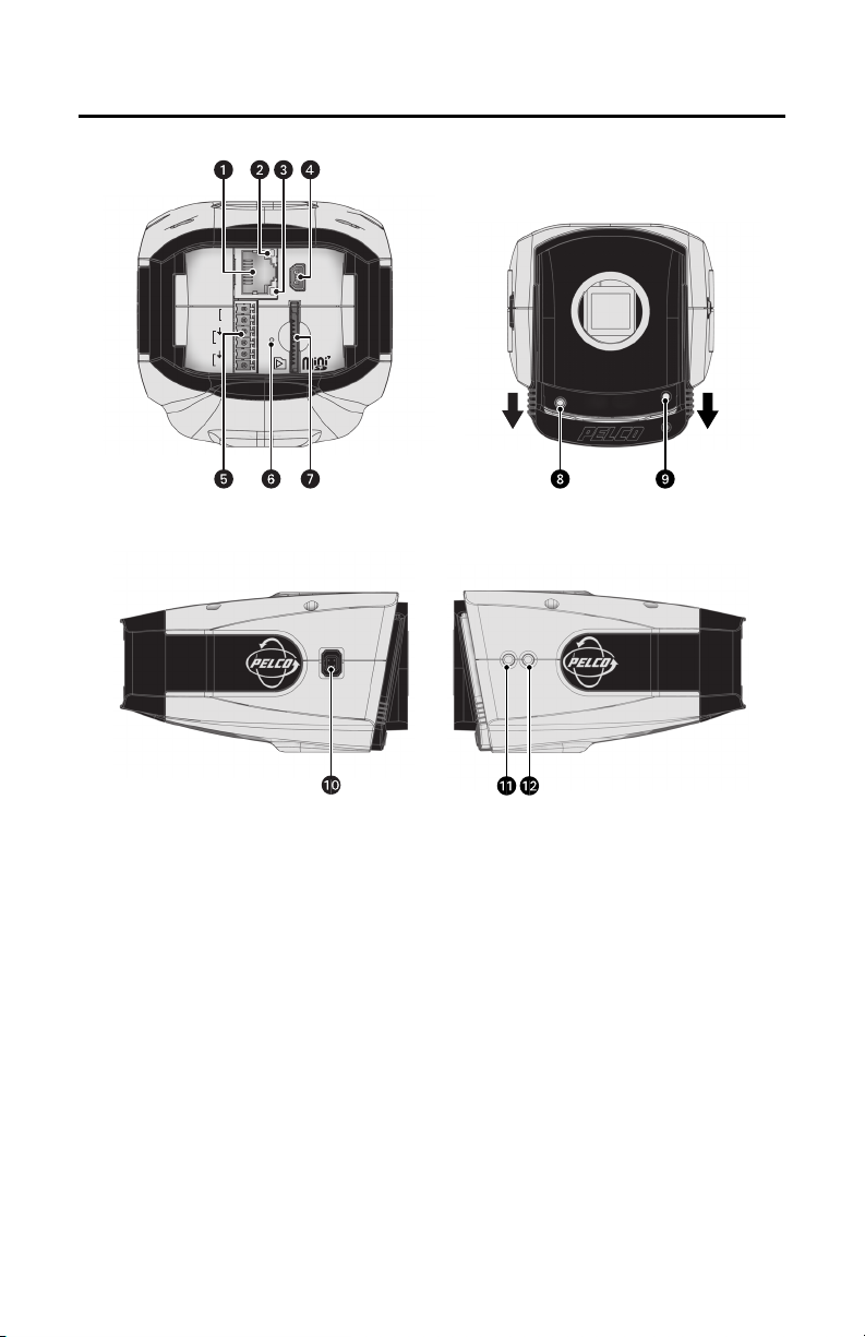
Figure 1. Camera Connections and Features
2 C2951M-A (2/09)
Page 3

ì
RJ-45 Connector: Supplies power to the camera through the network using PoE. If PoE is not
available, the camera is prewired for 24 VAC.
î
Ethernet Activity LED: Flashes green to indicate that data is being transmitted/received by the
camera.
ï
Ethernet Link LED: Glows solid amber to indicate that a live connection is established.
ñ
Accessory Port: Reserved for future use.
ó
24 VAC Power, Relay, and Alarm Connections: Supports 24 VAC as the power source, one
relay that can be used to control an external circuit, and one alarm for physical input into the
system.
r
Reset Button: Reboots the camera or restores the camera's factory default settings. This button is
recessed. Using a small tool, such as a paper clip, press and release the reset button once to reboot
the camera. Press and hold the reset button for 10 seconds to restore the camera to the factory
default settings.
s
Mini SD Card Slot: Saves a snapshot image to a mini SD card based on alarm activity.
t
Service Connector: Outputs analog video. Use this connector at the installation site to set up the
field of view and focus the camera. When a service cable is connected to the camera, video to the
IP stream is disabled.
u
Power LED: Glows solid green to indicate that the camera has power and flashes green during the
boot cycle. The LED can be disabled through the user interface. If this LED glows red (solid or
flashing), contact Pelco Product Support at 1-800-289-9100 (USA and Canada) or +1-559-292-1981
(International) for assistance.
~í
Auto Iris Lens Connector: Controls the auto iris lens. Insert the 4-pin connector from the DC drive
auto iris lens into this connector.
~â
Auto Back Focus Button: Sets the auto back focus mechanism. Press once to center the auto
back focus mechanism and fully open the iris. Press and hold the button for three seconds to start
the auto back focus mechanism and focus the camera.
~ä
NTSC/PAL Button: Toggles the service connector between NTSC and PAL formats. Press the
NTSC/PAL button to toggle between NTSC and PAL formats when using the service connector. The
default setting is NTSC.
NOTES:
• Pelco recommends connecting the camera to a network that uses a Dynamic Host Configuration
Protocol (DHCP) server to address devices.
• Do not use a HUB in the network setup of the camera.
• To secure access to the IP camera, place the camera behind a firewall when it is connected to a
network.
C2951M-A (2/09) 3
Page 4

Installation
NOTES:
• For detailed instructions, refer to the IX Series Installation/Operation manual (C2950M) or IXE Series
Installation/Operation manual (C2953M) available on the resource disc.
• Megapixel lenses are designed and tested to deliver optimal image quality to the IX Series and IXE
Series megapixel cameras. A standard definition lens installed on a megapixel camera will limit the
resolution of the camera and create poor image quality.
1. Install the lens:
a. Make sure the lens does not touch the camera imager when installed.
b. Screw the lens onto the lens mount. Be careful to prevent dust from entering the space
between the lens and the imager. If necessary, use clean, compressed air to remove any
foreign matter (refer to the instructions shipped with the lens).
c. Connect the auto iris lens to the 4-pin connector located on the side of the camera. Refer to
Figure 2 for pin designation and iris drive connector information.
3
12
2. Mount the camera in the desired location. The camera can be mounted from either the top or
bottom, depending on the type of camera mount used in your installation. Use a standard 1/4-20
screw. The maximum thread depth is 0.25 inches (6.4 mm).
NOTE: When installing inside an enclosure, mount the camera in an inverted position to allow easy
access to the service connector. Use the camera software to reconfigure the camera orientation for
normal operation.
4
Pin DC (AID) Auto Iris Lens
1 Control coil negative (-)
2 Control coil positive (+)
3 Drive coil positive (+)
4 Drive coil negative (-)
Figure 2. Lens Connections
4 C2951M-A (2/09)
Page 5

3. Plug the network cable into the RJ-45 connector located at the back of the camera (refer to Figure 3).
1
2
3
4
5
6
7
8
1
2
3
4
5
6
7
8
8 7 6 5 4 3 2 1
1
8
8
1
Pin Function
1TX+
2TX-
3RX+
4 PoE 1-2
5 PoE 1-2
1
2
3
4
5
6
7
8
8
7
6 5
4
3
2 1
6RX-
7 PoE 3-4
8 PoE 3-4
Figure 3. Pin Descriptions
4. Attach the supplied ferrite to the network cable. The ferrite should be installed on the cable
approximately 1 inch from the camera’s RJ-45 connector.
WARNING: The ferrite must be installed for the camera to meet FCC Class B compliance standards.
Failure to correctly install the ferrite might cause harmful interference to radio communications.
5. Connect the necessary wiring for alarms and relays (refer to Figure 4). Only use the 24 VAC wires if
PoE is not available.
24V~
RELAY
R1
ALARM
A1
Figure 4. Alarm and Relay Wiring
6. Apply power to the camera. View the camera image using the service jack or a Web browser.
7. Focus the lens:
a. Press the auto back focus button (located on the side of the camera) once to center the focus
mechanism.
b. Manually adjust the zoom and focus of the lens to the desired field of view (refer to the
instructions shipped with the lens).
c. Press and hold the back focus button for three seconds to make the final focus adjustments.
C2951M-A (2/09) 5
Page 6

Operation
Once the camera is installed, apply power to the camera. The camera will start a configuration sequence.
The green LED flashes five times per second for approximately two minutes, and then turns solid after the
boot cycle is complete and the camera is online.
IP ADDRESS SETTINGS
If the camera is connected to a DHCP network and DHCP is set to the On position, the server will
automatically assign an IP address to the device; DHCP On is the default setting for the camera. Set DHCP
to the Off position to manually set the camera’s IP address.
WARNING: If the camera is not connected to a DHCP server but DHCP is set to the On position, the
IP address 192.168.0.20 on subnet mask 255.255.255.0 is automatically assigned to the camera.
After the first camera is connected and assigned the default IP address, you must manually change
the IP address of the camera before connecting any additional cameras. Connecting a second
camera before changing the IP address of the first camera may result in a loss of communication to
one or both of the devices.
NOTES:
• Contact your network administrator to avoid network conflicts before setting/changing the camera’s
IP address.
• If you do not know the camera’s IP address, install the Pelco Device Utility software available on the
resource disc shipped with the product. The utility will locate the assigned name, IP address, and
MAC address for devices connected to the same virtual local area network (VLAN) as your computer.
The Device Utility software is also available at www.pelco.com/software/downloads/.
WEB BROWSER REQUIREMENTS
To use a Web browser with the IP camera, your equipment must meet the following minimum system
requirements:
• PC with Windows
– IX Series models: Pentium
– IXE Series models: Intel
•RAM
– IX Series models: 512 Mbyte
– IXE Series models: 2 GB
• Ethernet Card: 100 Mbit
• Screen resolution of 1024 x 768 pixels or higher, 16- or 32-bit pixel color resolution
• Microsoft
NOTE: Internet Explorer is not supported by Mac OS X 10.4.
•QuickTime
®
XP, Windows Vista®, or Mac® OS X 10.4
®
Internet Explorer® 7 (or later) or Mozilla® Firefox® 3.0 (or later)
®
7.5 (or later)
®
4 microprocessor, 1.6 GHz
®
Core™ 2 Duo microprocessor, 2.6 GHz
LOGGING ON TO THE CAMERA
To log on to the camera:
1. Click Login. A login dialog box opens.
2. Type admin (all lowercase) in the User ID and Password boxes (admin is the default for both boxes).
3. Click Log In.
NOTE: For security purposes, be sure to change the password after you log on for the first time.
6 C2951M-A (2/09)
Page 7

LIVE PAGE ICONS
Viewable icons are based on group permissions. The camera has two predefined groups: Public and Admin.
Public: This defined group can be modified or deleted. The default permission for this group is single
stream view.
Admin: This is the only defined group that cannot be deleted; however, the administrator password can be
changed. For security purposes, it is important that you change your password after you log on to the
device for the first time. This group has access to all permissions.
Show Device List: Displays a list of viewable cameras connected to the same VLAN as the
camera to which you are logged on.
Disable Viewer: Closes the live view window.
1 x 1 Mode: Displays a single video pane.
2 x 2 Mode: Displays 4 video panes in rows of two.
3 x 3 Mode: Displays 9 video panes in rows of three.
4 x 4 Mode: Displays 16 video panes in rows of four.
Select Stream: Selects the viewable video stream (primary or secondary) and selects
unicast or multicast settings.
Maximize Viewing Area: Scales the image to the full size of the browser.
Show Toolbar: Returns the screen to normal view. This icon is only available after the
screen has been set to maximize viewing area.
Open Stream in New Window: Opens the video in a scalable, independent window.
Opening the video in a separate window allows you to view the video while other
applications are running.
Take a Snapshot: Captures the image displayed in the video pane and saves it as a JPEG file.
C2951M-A (2/09) 7
Page 8

SETTINGS PAGE
Depending on user permissions, the Settings page allows you to manage camera system settings, set up
users and groups, and control the camera.
To access the camera settings:
1. Log on to the camera.
2. Click the Settings link in the navigation bar located in the upper-right corner of the page; a list of
menu tabs appear. Place the mouse pointer over a tab to display a list of submenus.
System Network
General General Select Preset Users Sources
SSL Exposure
SSH Focus
Imaging Video Streams
Custom Configuration Groups Handlers
Ton e M ap
White Balance
Users and Groups
General Settings
Events
Figure 5. Settings Page Menus
SYSTEM TAB
The System tab displays the firmware version, device name, enables/disables the power LED, allows
setup of the day and time settings, and permits event system email setup.
NETWORK TAB
Network Settings: Displays the hardware address, hostname, DHCP settings, and IP address settings.
SSL (Secure Socket Layers): Encrypts communications making it difficult for unauthorized users to
intercept and view user names and passwords.
SSH (Secure Shell): Allows Pelco Product Support to log on to and service the camera for advanced
troubleshooting purposes.
8 C2951M-A (2/09)
Page 9

IMAGING TAB
General: Includes camera orientation and digital processing settings. The orientation settings allow for
standard or inverted installation of the camera. The digital processing settings adjust the sharpness,
saturation, and contrast of the scene.
Exposure: Adjusts scene detail and contrast. A scene with correct exposure settings has adequate detail
and contrast between white and dark values. An image with too little or too much exposure eliminates
detail in the scene. The camera features auto and manual exposure settings.
Focus: Includes auto back focus and manual focus settings (refer to Focus in the IX Series Installation/
Operation manual [C2950M] or the IXE Series Installation/Operation manual [C2953M] for detailed
instructions). If the camera is programmed to automatically back focus, the camera will routinely refocus
when changes in the scene are detected. The camera will also run a quick autofocus sequence every three
hours to adjust the center focal point of the scene. This quick autofocus sequence compensates for
environmental temperature change and maintains optimal focus. If the auto back focus is turned off, the
autofocus mechanism locks the camera at a user-specified position. The camera will not focus if changes
in the scene occur. Manual focus is recommended only for indoor applications that have a single,
unchanging primary light source.
Ton e Ma p: Balances the brightest and darkest sections of an image to produce a picture with more
balanced lighting and more detail.
White Balance: Defines how the camera processes video images to render true colors in a scene. White
balance is especially effective in scenes with changing lighting conditions or in scenes with more than one
type of light source.
VIDEO STREAMS TAB
Select Preset: Selects preset camera configurations, which include primary and secondary video stream
settings available for easy setup.
Custom Configuration: Configures custom video stream settings. The camera features dual video
streams with programmable settings for compression, resolution, and image rate. The default names for
the streams are Primary and Secondary. Although each stream can be programmed independently, the
settings of one stream can limit the options available for the other stream depending on the bandwidth
consumed.
USERS AND GROUPS TAB
Users: Defines the permissions assigned to individuals logged on to the camera. Use this feature to
create, modify, or delete user accounts.
Groups: Defines the permissions assigned to users within a group. Use this setting to create, modify, and
delete groups and permissions. Multiple permissions can be assigned to each group.
General Settings: Changes the way the camera manages the users and groups settings. These settings
can be managed on a camera-to-camera basis or by using a centralized server to apply changes to multiple
cameras.
EVENTS TAB
Sources: Defines the camera functions that are automatically triggered by an event source. The camera
supports alarm, system, and timer event sources.
Handlers: Defines the actions that a camera takes when an event occurs. The camera supports four event
handlers: Send Email, Write JPEG to SD Card, Upload JPEG to FTP Server, and Open/Close Relay.
C2951M-A (2/09) 9
Page 10

Page 11

REVISION HISTORY
Manual # Date Comments
C2951M 1/09 Original version.
C2951M-A 2/09 Revised installation instructions.
Pelco, the Pelco logo, Camclosure, Digital Sentry, Endura, Esprit, ExSite, Genex, Intelli-M, Legacy, and Spectra are registered trademarks of Pelco, Inc.
Spectra III and Sarix are trademarks of Pelco, Inc.
All product names and services identified t hroughout this document are trademarks or registered trademarks of their re spective companies.
The absence of a trademark or registered trademark from this document does not constitute a waiver of intellectual property rights.
© Copyright 2009, Pelco, Inc. All rights reserved.
Page 12

www.pelco.com
Pelco, Inc. Worldwide Headquarters 3500 Pelco Way Clovis, California 93612 USA
USA & Canada Tel (800) 289-9100 Fax (800) 289-9150
International Tel +1 (559) 292-1981 Fax +1 (559) 348-1120
 Loading...