

Page 1
C2293M-B-EN (12/16)
IMP121-1ES
IMP121-1RS
IMP221-1ES
IMP221-1RS
IMP321-1ES
IMP321-1RS
IMP521-1ES
IMP521-1RS
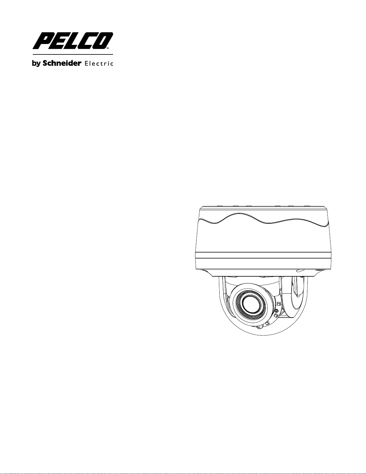
Sarix
®
Professional IMP
Series Environmental Vandal
Dome
Quick Start Guide
Page 2

Contents
Contents ....................................................................................................................................................................................... 2
Important Notices Statement ........................................................................................................................................................ 3
Regulatory Notices ......................................................................................................................................................... 3
Radio and Television Interference ................................................................................................................................. 3
Korean Class A EMC ............................................................................................................................................................ 3
Warranty Statement ..................................................................................................................................................................... 3
UL Safety Notices .......................................................................................................................................................... 3
Model Instructions ........................................................................................................................................................................ 4
Description ................................................................................................................................................................................... 5
Package Contents ........................................................................................................................................................................ 5
Optional Accessories .................................................................................................................................................................... 5
Installation .................................................................................................................................................................................... 5
In-Ceiling Flush Mount with IMPICM-1ER ...................................................................................................................... 6
Wall Surface Mount ........................................................................................................................................................ 8
Pendant Mount with IMPPM-1ER .................................................................................................................................. 9
Top Cover Defog .......................................................................................................................................................... 11
Position the Camera .................................................................................................................................................... 11
Adjusting the Focus ..................................................................................................................................................... 11
Pelco Troubleshooting Contact Information ............................................................................................................................... 12
Note for Dimension Drawings ..................................................................................................................................................... 12
2
Page 3
Important Notices Statement
For information about Pelco’s product-specific important notices and thereto related information, refer to www.pelco.com/legal.
REGULATORY NOTICES
This device complies with Part 15 of the FCC Rules. Operation is subject to the following two conditions: (1) this device may
not cause harmful interference, and (2) this device must accept any interference received, including interference that may
cause undesired operation.
RADIO AND TELEVISION INTERFERENCE
This equipment has been tested and found to comply with the limits of a Class A digital device, pursuant to Part 15 of the FCC
rules. These limits are designed to provide reasonable protection against harmful interference when the equipment is operated
in a commercial environment. This equipment generates, uses, and can radiate radio frequency energy and, if not installed
and used in accordance with the instruction manual, may cause harmful interference to radio communications. Operation of
this equipment in a residential area is likely to cause harmful interference in which case the user will be required to correct the
interference at his own expense.
Changes and Modifications not expressly approved by the manufacturer or registrant of this equipment can void your authority
to operate this equipment under Federal Communications Commission’s rules.
CAN ICES-3(A)/NMB-3(A)
Korean Class A EMC
Warranty Statement
For information about Pelco’s product warranty and thereto related information, refer to www.pelco.com/warranty.
UL SAFETY NOTICES
The product is intended to be supplied by a Listed Power Unit marked "L.P.S." (or "Limited Power Source") and rated output
24Vac, 50/60Hz, 1.28A minimum or 48Vdc, 0.35A minimum.
The product shall be installed by a qualified service person and the installation shall conform to all local codes.
3
Page 4

Model Instructions
Model
Description
IMP121-1ES
1MP Environmental Vandal Dome with Vari-focal lens
IMP121-1RS
1MP Environmental Vandal Dome with IR and Vari-focal lens
IMP221-1ES
2MP Environmental Vandal Dome with Vari-focal lens
IMP221-1RS
2MP Environmental Vandal Dome with IR and Vari-focal lens
IMP321-1ES
3MP Environmental Vandal Dome with Vari-focal lens
IMP321-1RS
3MP Environmental Vandal Dome with IR and Vari-focal lens
IMP521-1ES
5MP Environmental Vandal Dome with Vari-focal lens
IMP521-1RS
5MP Environmental Vandal Dome with IR and Vari-focal lens
The physical appearance and installation methods for the models indicated within the list below are, by and large, the same.
Therefore, please use this quick guide where we take the example from IMP521-1RS as a reference to apply to all the varied
models.
4
Page 5

Description
The Sarix® Professional Series IP Environmental Vandal Dome is ideal for both indoor and outdoor applications. Before
installing it, please verify your model and read this guide carefully
Package Contents
Environmental Vandal Dome camera * 1
Plastic Anchor * 4
Flat Head Screw (Tapping Type) * 4
T20 Security Torx Wrench * 1
Mounting Template * 2
Terminal Block * 1
Conduit Hole Plug * 1
Important Notices Declaration * 1
Printed Quick Start Guide * 1
Supplemental Resources Sheet * 1
Important Safety Instruction * 1
ROHS Statement Slip * 1
Optional Accessories
IMPICM-1ER: In-ceiling wall mount, for use with the environmental models
IMPPM-1ER: Pendant adapter, for use with the environmental models
IMPLD2-0ER: Lower dome (smoked)
IMPLD2-1ER: Lower dome (clear)
Installation
Sarix® Professional Series IP Environmental Vandal Dome can be installed by the following method.
In-Ceiling Flush Mount
Wall Surface Mount
Pendant mount (requires pendant mounting kit)
5
Page 6

IN-CEILING FLUSH MOUNT WITH IMPICM-1ER
1 2 3
4
Install the environmental vandal dome camera to an in-ceiling area as shown in the following procedure.
1. Utilize torx wrench to loosen the screws on lens base and top cover in order to disassemble the 3 parts of camera individually.
2. Connect the required cables (Ethernet and Alarm/Audio Input/Output threads) with the corresponding ports on rear side.
3. Attach the mounting template onto an in-ceiling surface followed by drilling a hole based on the template indication.
4. Embed the in-ceiling mount bracket into the hole that was drilled based on the mounting template.
6
Page 7

5. Use a cross screw driver to turn the 2 bracket screws clockwise to extend the locking arms and tighten them securely to
5
6
10
Protective Cover
Spring Hook * 2
Tightening torque: 8 ~ 10kg/cm
(17.64 ~ 22.05 lb/in)
Tightening torque: 8 ~ 10kg/cm
(17.64 ~ 22.05 lb/in)
compress the locking arms so that the bracket can be fixed within the in-ceiling area firmly.
6. Based on your needs, use the bottom conduit hole or side conduit hole on lower case for cable entry and connect the cables.
NOTE: Please properly lock the conduit hole plug on the unused hole. For example, lock the side conduit hole with the
plug while using the bottom conduit hole for cable entry and vice versa.
7. Fix the lower case onto the in-ceiling bracket by fastening the 4 screws followed by aligning the identifying red dots of
lower case and lens base to properly assemble them together with securing the 3 lens base screws.
8. After adjusting focus position to the satisfied field of view, mount the top cover on the lens base, both of which have a red
dot respectively also for aligning identification and tighten the 3 top cover screws firmly.
9. Attach the 2 spring hooks flanked the protective cover to the in-ceiling bracket for mounting completion.
NOTE: It is strongly recommended that you first ensure the mounting area is stable enough to withstand the in-ceiling
bracket and locking arms clamping on the ground of safety concern.
7
Page 8

WALL SURFACE MOUNT
Tightening torque: 8 ~ 10kg/cm
(17.64 ~ 22.05 lb/in)
Tightening torque: 8 ~ 10kg/cm
(17.64 ~ 22.05 lb/in)
Install the environmental vandal dome camera to a wall surface as shown in the following procedure.
1. Based on your needs, use the bottom or side conduit hole on the lower case for cable entry and connect the required
cables first. Then mount the lower case on a surface by securing screws (supplied) into the inserted plastic anchors tightly.
2. Align the lower case and the lens base, both of which have a red dot on the top side respectively for aligning
identification. Use the red dots to properly align them and then securely fasten the 3 screws of the lens base to the
bottom case with torx key (supplied).
3. Adjust the focusing position by rotating, panning and tilting the camera lens base. When rotating the camera lens, do not
rotate it over the stop point.
4. Fit the inner liner over the camera lens base until it snaps into the place.
5. Mount the top cover on the lens base, both of which similarly have a red dot for aligning identification. Be aware that the
red dot of top cover is within interior instead of top side.
6. Use the torx wrench (supplied) to tighten the 3 top cover screws to complete mounting.
NOTE: Please properly lock the conduit hole plug on the unused hole. For example, lock the side conduit hole with the
plug while using the bottom conduit hole for cable entry and vice versa.
8
Page 9

PENDANT MOUNT WITH IMPPM-1ER
Pendant Wall Mount
Pendant Pole Mount
Adaptor Ring
Rubber O-Ring
Apply Waterproof Repellent
The Pendant Installation involves mounting IMPPM-1ER Sarix Environmental Pendant Mount for Environmental Vandal
Dome camera. The camera must be first installed within the pendant mount back box with an adaptor ring before assembled
with additional pendant mount brackets. Below are the recommended brackets, which are NOT provided, for additional
pendant mount applications for your reference.
NOTE: Mounts and conduits must be sealed to prevent condensation in the camera
1. Rotate the adaptor ring, which can connect with brackets of 1 1/2”-conform screw thread, clockwise to the pendant mount back
box securely as shown below. The rubber o-ring provides seal on grooves between back box and adaptor ring. Note that it is
highly suggested to apply waterproof repellent onto the upper screw thread as shown below for complete ingress protection.
The diagram in the right side is the back box mounted with the adaptor ring.
NOTE: Anti-seize compound should be applied on environmental pendant. Not doing so might prevent the unit from
being separated in the future. Waterproof tape can also be used to help prevent water ingress damage.
9
Page 10

2. After wires connection, attach the lens base to the pendant mount back box by aligning the red dots for identification of
Tightening torque: 8 ~ 10kg/cm
(17.64 ~ 22.05 lb/in)
Tightening torque: 8 ~ 10kg/cm
(17.64 ~ 22.05 lb/in)
both parts and securely fasten the 3 screws of the lens base with the torx wrench (supplied). Finally, assemble the top
cover with the lens base, both of which, similarly, have red dots for aligning identification, followed by fastening the 3
screws of top cover to complete the installation.
10
Page 11

TOP COVER DEFOG
A
B
C
Defog function, which heats up the camera to overcome certain extreme weather conditions (e.g., snow or frost) which may harm
the operation of camera, is embedded within this vandal camera. However, in order to prevent a scald incident from happening to
installers, the Defog heating function won’t be activated when the top cover is detached from the camera body as shown in the
following figure where a button at the camera body (marked red) is not pressed by the salient point of top cover (marked green).
Instead, when the salient point presses the button of camera body, the heating function will activate automatically.
POSITION THE CAMERA
Pan Adjustment (A): Rotate the lens base until you are satisfied with the field of view. Note that the side conduit hole of
the lower case is the point where the camera lens shouldn’t be rotated over.
Horizontal Rotation (B): Rotate 3D assembly in the lens base, but do not turn assembly more than 355° as this may
cause the internal cables to be twisted, disconnected, or broken.
Tilt Adjustment (C): Lift to open the inner liner, and tilt the camera lens to your desired angle. Restore the inner liner
back to its default position after adjustment.
NOTE: Limitation for three axes position: Pan range: ±177°, Rotate range: ±177°, Tilt range: 35°~ 90°
ADJUSTING THE FOCUS
1. View the camera image using the browser (refer to the user manual).
2. Use the settings in the Web interface (refer to the user manual) to adjust the zoom and focus of the lens to the desired
field of view.
3. Also, the focus can be adjusted by moving the zoom slider and using the Focus options in the live webpage.
NOTE: Focus adjustment is done exclusively with Web UI.
11
Page 12

Pelco Troubleshooting Contact Information
NOTE: VALUES IN PARENTHESES ARE INCHES; ALL OTHERS ARE CENTIMETERS.
ENVIRONMENTAL VANDAL DOME
If the instructions provided fail to solve your problem, contact Pelco Product Support at 1-800-289-9100 (USA and Canada) or
+1-559-292-1981 (international) for assistance. Be sure to have the serial number available when calling.
Do not try to repair the unit yourself. Leave maintenance and repairs to qualified technical personnel only.
Note for Dimension Drawings
12
Page 13

Pelco by Schneider Electric
3500 Pelco Way Clovis, California 93612 USA
(800) 289-9100 Tel (800) 289-9150 Fax
+1 (559) 292-1981 International Tel
+1 (559) 348-1120 International Fax
www.pelco.com
Pelco, the Pelco logo, and other trademarks associated with Pelco products referred to in this publication are trademarks of Pelco, Inc. or its affiliates.
ONVIF and the ONVIF logo are trademarks of ONVIF Inc. All other product names and services are the property of their respective companies.
Product specifications and availability are subject to change without notice.
© Copyright 2016, Pelco, Inc.
All rights reserved.
13
 Loading...