

Page 1
GFC Professional Multi
Series Environmental
Dome Camera
Installation Manual
C6615M (05/19)
IMD2007-1ES
Page 2

2
Contents
Important Notices ......................................................................................................................................................................... 3
Regulatory Notices [FCC Class A] ................................................................................................................................. 3
Radio and Television Interference ................................................................................................................................. 3
Legal Notice [Audio Notice] ............................................................................................................................................ 3
Video Quality Caution .................................................................................................................................................... 3
Frame Rate Notice Regarding User Selected Options ................................................................................................... 3
Open Source Software ................................................................................................................................................... 4
Korean Class A EMC ..................................................................................................................................................... 4
ESD Warning ................................................................................................................................................................. 4
Warranty ........................................................................................................................................................................ 4
Network Topology Statement ......................................................................................................................................... 4
Getting Started ............................................................................................................................................................................. 5
GFC Pro Multi Series Models ....................................................................................................................................................... 5
Installation .................................................................................................................................................................................... 6
Pelco Troubleshooting Contact Information ............................................................................................................................... 16
Note for Dimension Drawings ..................................................................................................................................................... 16
Page 3

3
Important Notices
REGULATORY NOTICES [FCC CLASS A]
This device complies with Part 15 of the FCC Rules. Operation is subject to the following two conditions: (1) this device may
not cause harmful interference, and (2) this device must accept any interference received, including interference that may
cause undesired operation.
RADIO AND TELEVISION INTERFERENCE
This equipment has been tested and found to comply with the limits of a Class A digital device, pursuant to Part 15 of the FCC
rules. These limits are designed to provide reasonable protection against harmful interference when the equipment is operated
in a commercial environment. This equipment generates, uses, and can radiate radio frequency energy and, if not installed
and used in accordance with the instruction manual, may cause harmful interference to radio communications. Operation of
this equipment in a residential area is likely to cause harmful interference in which case the user will be required to correct the
interference at his own expense.
Changes and Modifications not expressly approved by the manufacturer or registrant of this equipment can void your authority
to operate this equipment under Federal Communications Commission’s rules.
Cet appareil numérique de la classe A est conforme à la norme NMB-003 du Canada.
LEGAL NOTICE [AUDIO NOTICE]
SOME PELCO EQUIPMENT CONTAINS, AND THE SOFTWARE ENABLES, AUDIO/VISUAL AND RECORDING
CAPABILITIES, THE IMPROPER USE OF WHICH MAY SUBJECT YOU TO CIVIL AND CRIMINAL PENALTIES.
APPLICABLE LAWS REGARDING THE USE OF SUCH CAPABILITIES VARY BETWEEN JURISDICTIONS AND MAY
REQUIRE, AMONG OTHER THINGS, EXPRESS WRITTEN CONSENT FROM RECORDED SUBJECTS. YOU ARE SOLELY
RESPONSIBLE FOR INSURING STRICT COMPLIANCE WITH SUCH LAWS AND FOR STRICT ADHERENCE TO ANY/ALL
RIGHTS OF PRIVACY AND PERSONALTY. USE OF THIS EQUIPMENT AND/OR SOFTWARE FOR ILLEGAL
SURVEILLANCE OR MONITORING SHALL BE DEEMED UNAUTHORIZED USE IN VIOLATION OF THE END USER
SOFTWARE AGREEMENT AND RESULT IN THE IMMEDIATE TERMINATION OF YOUR LICENSE RIGHTS
THEREUNDER.
NOTE: Improper use of audio/visual recording equipment may subject you to civil and criminal penalties. Applicable laws
regarding the use of such capabilities vary between jurisdictions and may require, among other things, express written consent
from the recorded subjects. You are solely responsible for insuring strict compliance with such laws and for strict adherence to
any/all right of privacy and personality.
VIDEO QUALITY CAUTION
FRAME RATE NOTICE REGARDING USER SELECTED OPTIONS
Pelco systems are capable of providing high quality video for both live viewing and playback. However, the systems can be
used in lower quality modes, which can degrade picture quality, to allow for a slower rate of data transfer and to reduce the
amount of video data stored. The picture quality can be degraded by either lowering the resolution, reducing the picture rate,
or both. A picture degraded by having a reduced resolution may result in an image that is less clear or even indiscernible. A
picture degraded by reducing the picture rate has fewer frames per second, which can result in images that appear to jump or
move more quickly than normal during playback. Lower frame rates may result in a key event not being recorded by the
system.
Judgment as to the suitability of the products for users' purposes is solely the users' responsibility. Users shall determine the
suitability of the products for their own intended application, picture rate and picture quality. In the event users intend to use
the video for evidentiary purposes in a judicial proceeding or otherwise, users should consult with their attorney regarding any
particular requirements for such use.
Page 4
4
OPEN SOURCE SOFTWARE
This product includes certain open source or other software originated from third parties that is subject to the GNU General
Public License (GPL), GNU Library/Lesser General Public License (LGPL) and different and/or additional copyright licenses,
disclaimers, and notices.
The exact terms of GPL, LGPL, and some other licenses are provided to you with this product. Please refer to the exact terms
of the GPL and LGPL at http://www.fsf.org (Free Software Foundation) or http://www.opensource.org (Open Source Initiative)
regarding your rights under said license. You may obtain a complete corresponding machine-readable copy of the source code
of such software under the GPL or LGPL by sending your request to digitalsupport@pelco.com; the subject line should read
Source Code Request. You will then receive an email with a link for you to download the source code.
This offer is valid for a period of three (3) years from the date of the distribution of this product by Pelco.
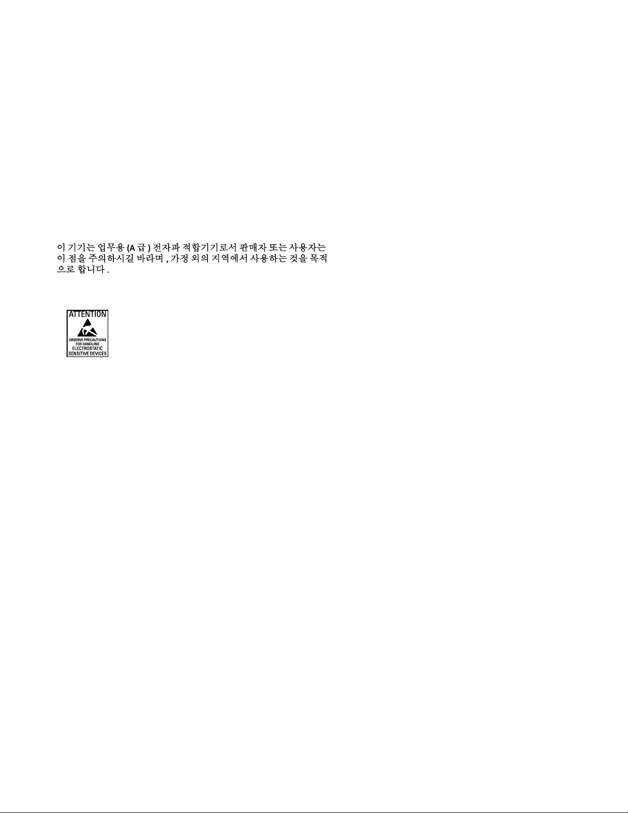
KOREAN CLASS A EMC
ESD WARNING
WARNING: This product is sensitive to Electrostatic Discharge (ESD). To avoid ESD damage to this product,
use ESD safe practices during installation. Before touching, adjusting or handling this product, correctly
attach an ESD wrist strap to your wrist and appropriately discharge your body and tools. For more
information about ESD control and safe handling practices of electronics, please refer to ANSI/ESD S20.201999 or contact the Electrostatic Discharge Association (www.esda.org).
WARRANTY
For information about Pelco’s product warranty and thereto related information, refer to www.pelco.com/warranty.
NETWORK TOPOLOGY STATEMENT
IMPORTANT NOTE. PLEASE READ. The network implementation is shown as a general representation only and is not
intended to show a detailed network topology. Your actual network will differ, requiring changes or perhaps additional network
equipment to accommodate the system as illustrated. Please contact your local Pelco representative to discuss your specific
requirements.
Page 5

5
Getting Started
Before installing your device, thoroughly familiarize yourself with the information in the installation section of this manual.
NOTES
• Pelco recommends connecting the device to a network that uses Dynamic Host Configuration Protocol (DHCP)
server to address devices.
• To ensure secure access, place the device behind a firewall when it is connected to a network.
NOTE:
• The product is intended to be supplied by a Listed Power Unit marked "L.P.S." (or "Limited Power Source")
and rated output:
• The product shall be installed by a qualified service person and the installation shall conform to all local
codes.
GFC Professional Multi Series Models
SUPPLIED PARTS LIST
QTY
DESCRIPTION
1
GFC Professional Multi Dome
1
I/O combo cable
2
Desiccant packs
1
Camera mounting plate
1
Installation alignment sticker
1
Printed installation manual and Important Safety Instructions
USER SUPPLIED PARTS LIST
QTY
DESCRIPTION
1
Drill
1
Screwdriver
1
Wire cutter
1
Ground wire
1
RJ-45 connector to terminate wires
1
Cat5 (or higher) cable
Page 6
6
Installation
Install the GFC Professional Multi Series Environmental Dome as shown in the following instructions:
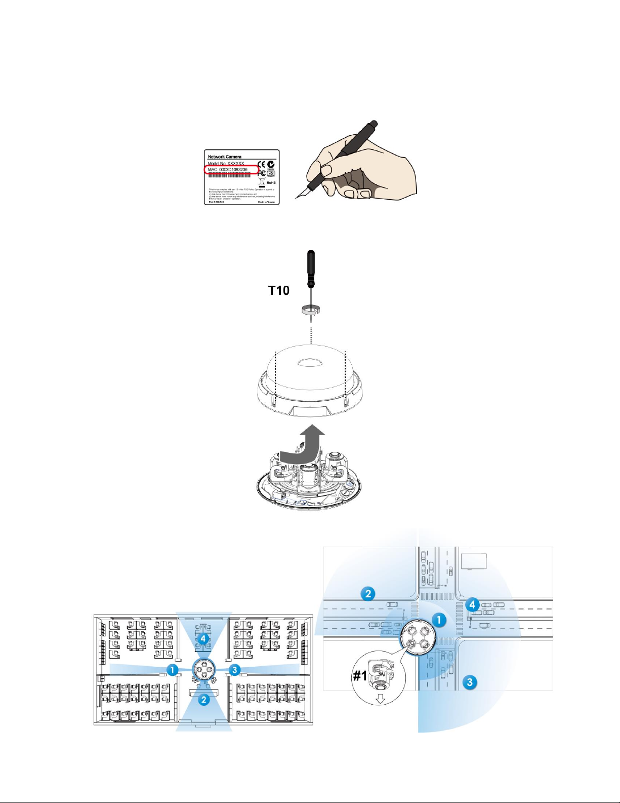
1. Jot down the camera’s MAC address for later reference.
2. Open the door cover by loosening four T10 anti-tamper screws. Hold the camera model still and twist the lower dome
slightly counterclockwise to unlock the hooks and open the camera.
3. With its remote focus lenses, the lens modules can be aiming at different areas at different distances.
Page 7

7
4. Remove the waterproof connectors. If you do not need to route I/O wires, leave the plastic cap in place. If you need to
connect I/O wires, keep the stainless nut.
5. Attach the alignment sticker to a position you prefer. Drill screw holes and a routing hole. Route cables through the
routing hole and secure the top mounting plate to ceiling by driving the included screws.
Page 8

8
6. Pass at least CAT5E Ethernet cable through the routing hole.
7. Hook up the tether wire between the camera and the top mounting plate.
8. Pass the Ethernet cable through the components of the waterproof cable gland.
Page 9

9
9. Remove part of the outer CAT5E or better Ethernet cable jacket and be careful not to damage the internal UTP wires.
Separate out the four pairs of wire and terminate these wires, following the standard TIA/EIA T568B. Make sure the
wires are pushed into the RJ45 plug so that they are fully inserted. Firmly crimp the RJ-45 plug so that the individual
wires and the outer sheath are all fully trapped inside the plug.
Note: Carefully route the ethernet cable under the lens plate (camera base) to avoid any damages to the microphone
pins and/or other exposed components. The picture on step 14 shows the wire routing.
10. Tighten and install the components of the waterproof connector.
Page 10

10
11. Pass the I/O combo cable (if applied) through the routing hole and attach a rubber seal ring. Install the combo cable
with the white headers inside the camera and tighten the stainless hex nut from the inside of the camera.
12. Connect the white headers to J9 and J14 heads on camera PCM board. Carefully route the cables along the camera
base.
Page 11

11
1. The DO+ pin provides a 5V output voltage, and the max. load is 50mA.
2. The max. voltage for DO- pins is 30VDC (External power). In order to control AC devices, the above diagram
can be taken in consideration. The diagram uses a relay to control the ON/OFF condition of the AC device.
3. An external relay can be triggered by using DO+ or by an external power source, depending on the type of relay
you use.
4. In case of using an individual relay (instead of using a relay module), for protection against voltage or current
spikes, a transient voltage suppression diode must be connected in parallel with the inductive load.
Page 12

12
13. On the outside of the cameras, the I/O wires connection should be protected against moisture by using electrical
insulation putty.
14. Install a Micro SD card if applicable.
15. When the Ethernet and I/O wires connection is complete, and the camera is powered up, try to find the camera using
Pelco’s VideoXpert.
16. DoubleClick on the camera’s entry on VMS to open a web console with the camera. A browser session will open. The
program will search for Pelco video receivers, video servers, or network cameras on the same LAN.
17. Use a ground wire (user supplied, with a resistance lower the 4Ω, a diameter larger than 20AWG) and an M4 screw
to connect it to the ground rod.
Page 13

13
18. Secure the camera to the top mounting plate by using the alignment marks. Align and then rotate the camera
clockwise.
19. When done, the camera will snap in place on the mounting plate.
20. If you are not sure whether the field of view can properly cover the area of your interest, you can check the live view
at the installation site.
21. With a live view displayed on your laptop, you can adjust the lens shooting direction to obtain an optimal field of view.
Check the live view to ensure the image is in focus.
Page 14

14
22. You can move a lens module from side to side, turn the lens shooting direction up or down, or rotate the module to
cover the area of your interest. Note: Stay within the pan range (180º) and rotation range (±90º each lens). When
adjusting the shooting angle, please avoid touching the exposed circuit board or ribbon cable. Static discharge can
cause damages.
23. Perform necessary adjustments such as the image alignments on the panoramic view from the 4 sensors. Go to
Confirmation>Media>Image>Focus. Zoom in on the individual lens if necessary. The automated focus function can
help you acquire the best image.
Page 15

15
24. Replace the two desiccant bags on the sides of the camera. Desiccant is used to absorb moisture in the camera.
Replace the desiccant every time you open the dome cover. Note: Do not forget to install the new provided desiccant
bags. Otherwise, condensation might build in the lens. Secure the desiccant packs to the back housing to prevent
them from falling and obstructing the lens field of view.
25. Align the center of the dome cover (the center of the Pelco logo) with the alignment mark on the camera body. Aim
and then turn clockwise. Install the dome cover by fastening the T10 anti-tamper screws. You may need to carefully
route the safety tether aside. Complete the installation by tightening the T10 Screw on the side of the mounting plate
to 9 in-lbs (1.0 Nm). This will ensure the camera is secure in the mounting plate.
Page 16

16
Pelco Troubleshooting Contact Information
If the instructions provided fail to solve your problem, contact Pelco Product Support at 1-800-289-9100 (USA and Canada) or
+1-559-292-1981 (international) for assistance. Be sure to have the serial number available when calling.
Do not try to repair the unit yourself. Leave maintenance and repairs to qualified technical personnel only.
Note for Dimension Drawings
NOTE: VALUES IN PARENTHESES ARE INCHES; ALL OTHERS ARE CENTIMETERS.
REVISION HISTORY
Manual # Date Comments
C26615M 03/19 Rev.01
Pelco, the Pelco logo, and other trademarks associated with Pelco products referred to in this publication are trademarks of Pelco, Inc. or its affiliates. © Copyright 2019, Pelco, Inc.
ONVIF and the ONVIF logo are trademarks of ONVIF Inc. All other product names and services are the property of their respective companies. All rights reserved.
This equipment contains electrical or electronic components that must be recycled properly to comply with Directive 2002/96/EC
of the European Union -regarding the disposal of waste electrical and electronic equipment (WEEE). Contact your local dealer
for procedures for recycling this equipment.
Page 17

Pelco, Inc.
625 W. Alluvial Ave.
Fresno, CA 93711
Tel. +1 559-292-1981
www.pelco.com
Pelco, the Pelco logo, and other trademarks associated with Pelco products referred to in this publication are trademarks of Pelco, Inc. or its
affiliates. ONVIF and the ONVIF logo are trademarks of ONVIF Inc. All other product names and services are the property of their respective
companies. Product specifications and availability are subject to change without notice. ©Copyright 2019, Pelco, Inc. All rights reserved.
 Loading...