

Page 1
C1463M-A (12/00)
PDF8 Series
Pendant Fixed Mount Dome
®
3500 Pelco Way
Clovis, CA 93612-5699
USA
In North America & Canada:
Tel (800) 289-9100
FAX (800) 289-9150
DataFAX (800) 289-9108
International Customers:
Tel +1(559) 292-1981
FAX +1(559) 348-1120
DataFAX +1(559) 292-0435
PelcoEurope BV
Dillenburg Center
Dillenburgstraat 5F
5652 AM Eindhoven
The Netherlands
Tel +31(40) 251-9870
FAX +31(40) 251-9835
Pelco Online
www.pelco.com
IMPORTANT SAFEGUARDS AND WARNINGS
Prior to installation and use of this product, the following WARNINGS should be observed.
1. Installation and servicing should only be done by qualified service personnel and conform
to all local codes.
2. Unless the unit is specifically marked as a NEMA Type 3, 3R, 3S, 4, 4X ,6 or 6P enclosure,
it is designed for indoor use only and it must not be installed where exposed to rain and
moisture.
3. Only use replacement parts recommended by Pelco.
4. The installation method and materials should be capable of supporting four times the
weight of the enclosure, pan/tilt, camera and lens combination.
Please thoroughly familiarize yourself with the information in this manual prior to installation and
operation.
DESCRIPTION
PDF8 Series domes are pendant style units designed for indoor use only. The dome can be
mounted to a ceiling or wall using a suitable length pipe (threaded at both ends) and a mount/
adapter. All PDF8 Series pendant domes are compatible with Pelco IWM Series Wall Mount, the
MRWA Wall Mount, and the MRCA Ceiling Mount.
Models
PDF8-0 Pendant dome with opaque black bubble and smoked viewing slot (1/2 f-stop
of light loss)
PDF8-1 Same as the PDF8-0 except bubble is opaque black with a clear viewing slot
NOTE:
The length of pipe used
may cause noticeable motion on
the video display. If this occurs,
the pipe will require additional
support by bracing, guy wires, etc.
CAUTION:
The mount
area must be capable of
supporting up to 40
pounds (18.12 kg) of weight.
INSTALLATION
Mount, Back Box Cap and Back Box Installation
1 Refer to the instructions supplied with
the IWM, MRWA, or MRCA to install the
mount for the PDF8 Series dome. Bring
the wiring for the dome through the
mount. Refer to Tables A and B for wiring distances.
2 Install a threaded pipe with a minimum
length of 2.50-inches into the mount.
Tighten the pipe to the mount with torque
of approximately 30 ft-lb.
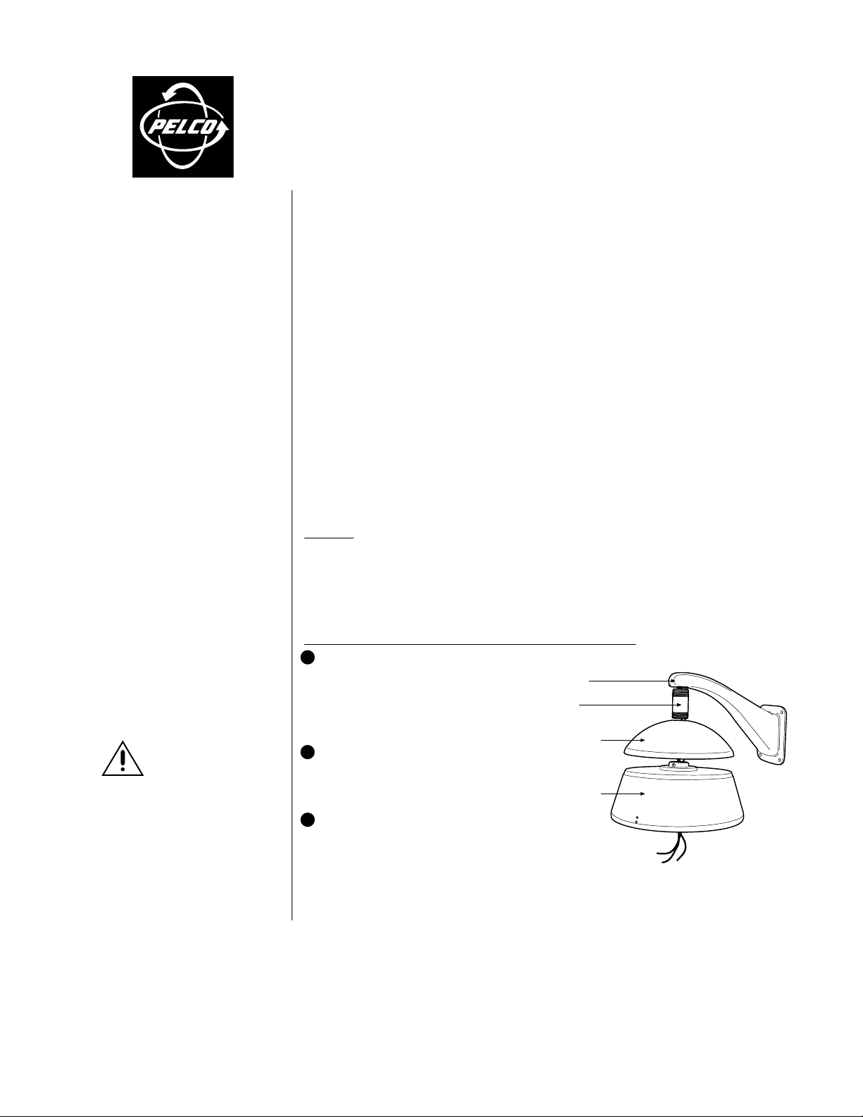
3 Refer to Figure 1 and install the back
box cap and back box. Pull wiring from
the mount through the back box cap and
into the back box. Slide the back box
cap over the pipe and screw the back
box onto the threaded pipe. Tighten the
back box by lightly applying torque, approximately 20 ft-lb.
MOUNT
PIPE
(NOT SUPPLIED)
BACK BOX
CAP
BACK BOX
Figure 1. Back Box Cap and Back Box
Installation
Page 2
Camera and Lens Installation
1 Refer to Figure 2 and attach the tilt table assembly to the back box with the supplied black
fender washer, lock washer, and wing nut. Tighten the wing nut.
2 Attach the camera and lens to the tilt table with the 1/4-20 screw and washers (supplied).
Adjust the tilt table by loosening the bolts on the side of the tilt table assembly. Position the
tilt table where desired and tighten the bolts.
3 Do the following to ensure that the lens will not hit the viewing window when installed:
a. Extend the lens to the maximum length.
b. Place the lower dome over the back box with the camera and lens installed (do not
attach dome).
c. If the lens touches the lower dome, adjust the tilt table assembly.
4 Refer to the Operation Manual supplied with the camera and lens, for the following information:
a. How to connect power and video wiring.
b. How to make camera and lens adjustments.
TILT TABLE
ASSEMBLY
ADJUSTMENT
TILT TABLE
BOLT
POSITIONING
RIVETS
Figure 2. Camera and Lens Installation
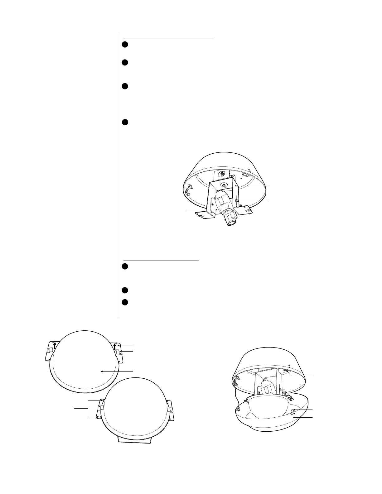
Lower Dome Installation
1 Refer to Figure 3 and install the acrylic viewing dome by sliding one side of the dome under
the retaining clips on the tilt table assembly. Seat the dome to the edge of the positioning
rivets.
2 Turn the dome so that the viewing slot is in front of the camera lens.
3 Refer to Figure 4 and install the bezel on the back box by lining up the pins with the holes
located on the edge of the back box. Apply light pressure to the top of the bezel. Turn the
bezel clockwise and release pressure.
TILT TABLE
RETAINING CLIP
VIEWING DOME
HOLE
PIN
BEZEL
Figure 3. Acrylic Viewing Dome Installation
Figure 4. Lower Dome and Bezel Installation
Page 3

T able A. Video Coaxial Cable Requirements
Cable Type* Maximum Distance
RG59/U 750 ft (229 m)
RG6/U 1,000 ft (305 m)
RG11/U 1,500 ft (457 m)
* Minimum cable requirements:
75 ohms impedance
All-copper center conductor
All-copper braided shield with 95% braid coverage
Table B. 24 VAC Wiring Distances
The following are the recommended maximum distances for 24 VAC applications and are
calculated with a 10-percent voltage drop. (Ten percent is generally the maximum allowable
voltage drop for AC-powered devices.)
EXAMPLE:
An enclosure
that requires 80 vA and is installed 35 feet (10 m) from
the transformer would require a minimum wire gauge
of 20 AWG.
NOTE:
Wire gauges are
standard AWG or metric
sizes. Distances are calculated in feet; values in
parentheses are meters.
Wire Gauge
Total
vA (0.5 mm2) (1.0 mm2) (1.5 mm2) (2.5 mm2) (4.0 mm2) (6.0 mm2)
10 283 451 716 1142 1811 2880
20 141 225 358 571 905 1440
30 94 150 238 380 603 960
40 70 112 179 285 452 720
50 56 90 143 228 362 576
60 47 75 119 190 301 480
70 40 64 102 163 258 411
80 35 56 89 142 226 360
90 31 50 79 126 201 320
100 28 45 71 114 181 288
110 25 41 65 103 164 261
120 23 37 59 95 150 240
130 21 34 55 87 139 221
140 20 32 51 81 129 205
150 18 30 47 76 120 192
160 17 28 44 71 113 180
170 16 26 42 67 106 169
180 15 25 39 63 100 160
190 14 23 37 60 95 151
200 14 22 35 57 90 144
20 18 16 14 12 10
(86) (137) (218) (348) (551) (877)
(42) (68) (109) (174) (275) (438)
(28) (45) (72) (115) (183) (292)
(21) (34) (54) (86) (137) (219)
(17) (27) (43) (69) (110) (175)
(14) (22) (36) (57) (91) (146)
(12) (19) (31) (49) (78) (125)
(10) (17) (27) (43) (68) (109)
(9) (15) (24) (38) (61) (97)
(8) (13) (21) (34) (55) (87)
(7) (12) (19) (31) (49) (79)
(7) (11) (17) (28) (45) (73)
(6) (10) (16) (26) (42) (67)
(6) (9) (15) (24) (39) (62)
(5) (9) (14) (23) (36) (58)
(5) (8) (13) (21) (34) (54)
(4) (7) (12) (20) (32) (51)
(4) (7) (11) (19) (30) (48)
(4) (7) (11) (18) (28) (46)
(4) (6) (10) (17) (27) (43)
Maximum distance from transformer to load
Page 4

MAINTENANCE
To clean the inside or outside of the plastic viewing dome, use a soft cloth that will not scratch
the surface. If you use any liquid cleaner, make sure it is safe for acrylic plastic.
Service Manual
If you need to service your unit, obtain a service manual in one of the following ways:
• Go to Pelco’s web site at ftp://www.pelco.com and find service manual C1463SM.
• Call Pelco’s DataFAX service at 1-800-289-9108 or 1-559-292-0435 and request document
214638.
• Contact Pelco’s Literature Department and request service manual C1463SM.
SPECIFICATIONS
GENERAL
Environment: Indoor only
Operating Range: 32° to 120°F (0° to 49°C)
Weight: 8.25 lb (3.74 kg)
MECHANICAL
Construction
Back Box: Aluminum
Cap: Aluminum
Bezel: Aluminum
Viewing Window: Acrylic plastic
Finish: Black polyester powder coat
Cable Entry: Top of dome
Dimensions: See Dimension Drawing
Maximum Camera/
Lens Size (Dimensions include BNC connector)
Horizontal: 7.0 (L) x 4.5 (W) x 3.0 (H) inches (17.78 x 11.43 x 7.62 cm)
15 degrees: 10.0 (L) x 4.5 (W) x 2.0 (H) inches (25.4 x 11.43 x 5.08 cm)
30 degrees: 12.0 (L) x 4.5 (W) x 2.5 (H) inches (30.48 x 11.43 x 6.35 cm)
(Design and specifications are subject to change without notice.)
WARRANTY AND RETURN INFORMATION
WARRANTY
Pelco will repair or replace, without charge, any merchandise proved defective in
material or workmanship for a period of one year after the date of shipment. Exceptions to this warranty are as noted below:
• Three years on Genex® Series (multiplexers, server, and keyboard).
• Two years on cameras and all standard motorized or fixed focal length lenses.
• Two years on Legacy®, Camclosure™ Camera Systems, CM6700/CM8500/
CM9500/CM9750/CM9760 Matrix, PelcoVision®, DF5 Series and DF8 Fixed Dome
products.
• Two years on Spectra
applications.
• Two years on WW5700 series window wiper (excluding wiper blades).
• Six months on all pan and tilts, scanners or preset lenses used in continuous
motion applications (that is, preset scan, tour and auto scan modes).
Pelco will warrant all replacement parts and repairs for 90 days from the date of Pelco
shipment. All goods requiring warranty repair shall be sent freight prepaid to Pelco,
Clovis, California. Repairs made necessary by reason of misuse, alteration, normal
wear, or accident are not covered under this warranty.
Pelco assumes no risk and shall be subject to no liability for damages or loss resulting from the specific use or application made of the Products. Pelco’s liability for any
claim, whether based on breach of contract, negligence, infringement of any rights of
any party or product liability, relating to the Products shall not exceed the price paid
by the Dealer to Pelco for such Products. In no event will Pelco be liable for any
special, incidental or consequential damages (including loss of use, loss of profit and
claims of third parties) however caused, whether by the negligence of Pelco or otherwise.
The above warranty provides the Dealer with specific legal rights. The Dealer may
also have additional rights, which are subject to variation from state to state.
®
and Esprit™, including when used in continuous motion
If a warranty repair is required, the Dealer must contact Pelco at (800) 289-9100
or (559) 292-1981 to obtain a Repair Authorization number (RA), and provide
the following information:
1. Model and serial number
2. Date of shipment, P.O. number, Sales Order number, or Pelco invoice number
3. Details of the defect or problem
If there is a dispute regarding the warranty of a product which does not fall
under the warranty conditions stated above, please include a written explanation with the product when returned.
Method of return shipment shall be the same or equal to the method by which
the item was received by Pelco.
RETURNS
In order to expedite parts returned to the factory for repair or credit, please call
the factory at (800) 289-9100 or (559) 292-1981 to obtain an authorization number (CA number if returned for credit, and RA number if returned for repair).
Goods returned for repair or credit should be clearly identified with the assigned
CA/RA number and freight should be prepaid. All merchandise returned for credit
may be subject to a 20% restocking and refurbishing charge.
Ship freight prepaid to: Pelco
3500 Pelco Way
Clovis, CA 93612-5699
REVISION HISTORY
Manual # Date Comments
C1463M 6/97 Original version.
C1463M-A 12/00 Revised installation instructions and illustrations. Updated manual to new format.
® Pelco, the Pelco logo, Spectra, Genex, Legacy, and PelcoVision are registered trademarks of Pelco. © Copyright 2000, Pelco.
™ Esprit and Camclosure are trademarks of Pelco. All rights reserved.
8/97 Revised available model numbers.
 Loading...