

Page 1
OPERATION
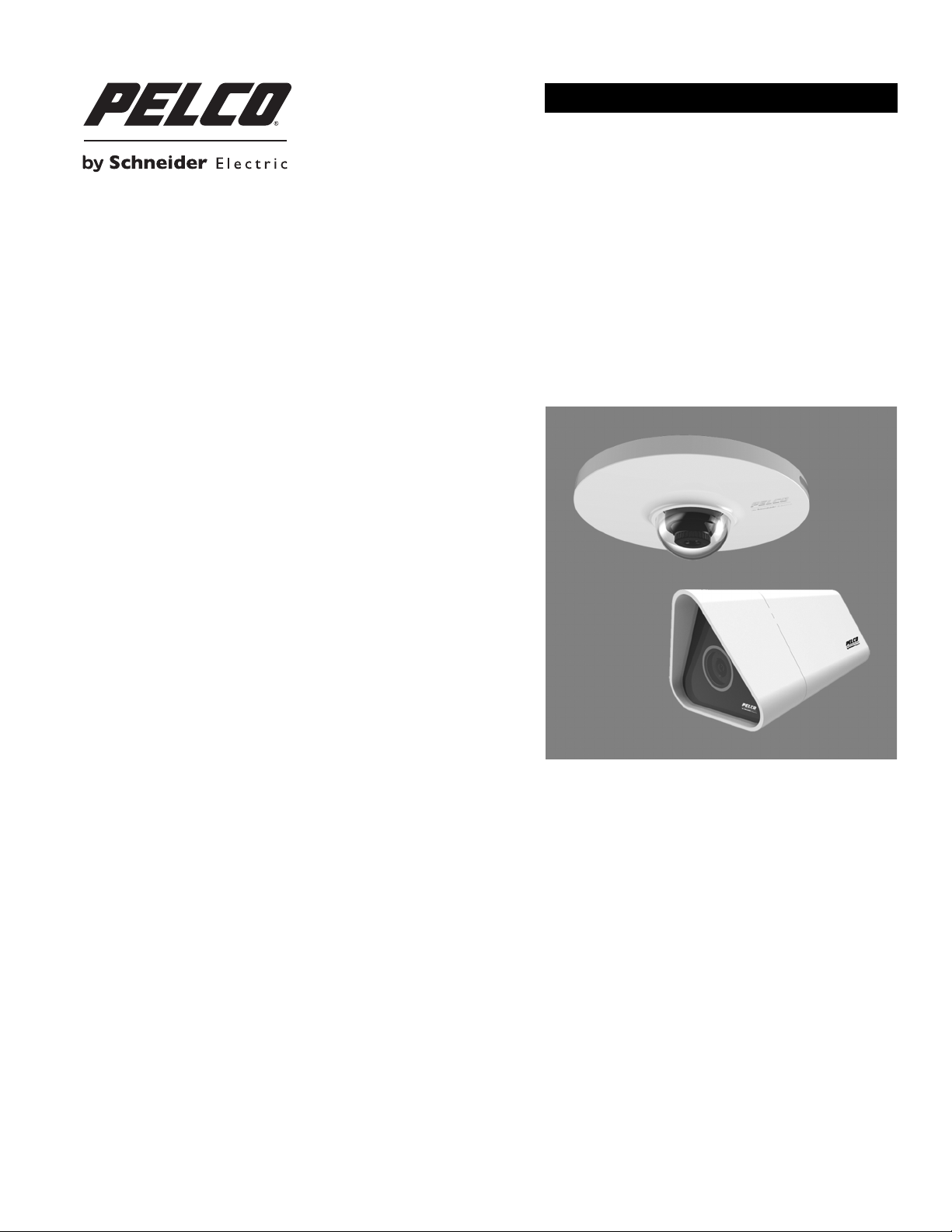
Sarix® IL10 Series IP Camera
Box Camera
Micro Dome Camera
C3916M (2/13)
Page 2

Contents
Important Notices . . . . . . . . . . . . . . . . . . . . . . . . . . . . . . . . . . . . . . . . . . . . . . . . . . . . . . . . . . . . . . . . . . . . . . . . . . . . . . . . . . . . . . . . . . . . . . . . . . . . . 5
Regulatory Notices . . . . . . . . . . . . . . . . . . . . . . . . . . . . . . . . . . . . . . . . . . . . . . . . . . . . . . . . . . . . . . . . . . . . . . . . . . . . . . . . . . . . . . . . . . . . . . . . 5
Legal Notice . . . . . . . . . . . . . . . . . . . . . . . . . . . . . . . . . . . . . . . . . . . . . . . . . . . . . . . . . . . . . . . . . . . . . . . . . . . . . . . . . . . . . . . . . . . . . . . . . . . . . 5
Introduction . . . . . . . . . . . . . . . . . . . . . . . . . . . . . . . . . . . . . . . . . . . . . . . . . . . . . . . . . . . . . . . . . . . . . . . . . . . . . . . . . . . . . . . . . . . . . . . . . . . . . . . . . . 6
Operation . . . . . . . . . . . . . . . . . . . . . . . . . . . . . . . . . . . . . . . . . . . . . . . . . . . . . . . . . . . . . . . . . . . . . . . . . . . . . . . . . . . . . . . . . . . . . . . . . . . . . . . . . . . . 7
Camera Configuration Sequence . . . . . . . . . . . . . . . . . . . . . . . . . . . . . . . . . . . . . . . . . . . . . . . . . . . . . . . . . . . . . . . . . . . . . . . . . . . . . . . . . . . . . 7
Minimum System Requirements . . . . . . . . . . . . . . . . . . . . . . . . . . . . . . . . . . . . . . . . . . . . . . . . . . . . . . . . . . . . . . . . . . . . . . . . . . . . . . . . . . . . . 7
Accessing the IP Camera . . . . . . . . . . . . . . . . . . . . . . . . . . . . . . . . . . . . . . . . . . . . . . . . . . . . . . . . . . . . . . . . . . . . . . . . . . . . . . . . . . . . . . . . . . . 7
Live Video Page . . . . . . . . . . . . . . . . . . . . . . . . . . . . . . . . . . . . . . . . . . . . . . . . . . . . . . . . . . . . . . . . . . . . . . . . . . . . . . . . . . . . . . . . . . . . . . . . . . . . . . . 8
Live Video Page Icons . . . . . . . . . . . . . . . . . . . . . . . . . . . . . . . . . . . . . . . . . . . . . . . . . . . . . . . . . . . . . . . . . . . . . . . . . . . . . . . . . . . . . . . . . . . . . . 8
Keyboard Shortcuts. . . . . . . . . . . . . . . . . . . . . . . . . . . . . . . . . . . . . . . . . . . . . . . . . . . . . . . . . . . . . . . . . . . . . . . . . . . . . . . . . . . . . . . . . . . . . . . .8
Selecting a Stream . . . . . . . . . . . . . . . . . . . . . . . . . . . . . . . . . . . . . . . . . . . . . . . . . . . . . . . . . . . . . . . . . . . . . . . . . . . . . . . . . . . . . . . . . . . . . . . . 9
Settings Page. . . . . . . . . . . . . . . . . . . . . . . . . . . . . . . . . . . . . . . . . . . . . . . . . . . . . . . . . . . . . . . . . . . . . . . . . . . . . . . . . . . . . . . . . . . . . . . . . . . . . . . . 10
Accessing the Camera Menus . . . . . . . . . . . . . . . . . . . . . . . . . . . . . . . . . . . . . . . . . . . . . . . . . . . . . . . . . . . . . . . . . . . . . . . . . . . . . . . . . . . . . .10
Logging On to the Camera . . . . . . . . . . . . . . . . . . . . . . . . . . . . . . . . . . . . . . . . . . . . . . . . . . . . . . . . . . . . . . . . . . . . . . . . . . . . . . . . . . . . . . 7
Primary Stream and Secondary Stream. . . . . . . . . . . . . . . . . . . . . . . . . . . . . . . . . . . . . . . . . . . . . . . . . . . . . . . . . . . . . . . . . . . . . . . . . . . . 9
Quickview Stream . . . . . . . . . . . . . . . . . . . . . . . . . . . . . . . . . . . . . . . . . . . . . . . . . . . . . . . . . . . . . . . . . . . . . . . . . . . . . . . . . . . . . . . . . . . . 9
Unicast . . . . . . . . . . . . . . . . . . . . . . . . . . . . . . . . . . . . . . . . . . . . . . . . . . . . . . . . . . . . . . . . . . . . . . . . . . . . . . . . . . . . . . . . . . . . . . . . . . . . . 9
Multicast . . . . . . . . . . . . . . . . . . . . . . . . . . . . . . . . . . . . . . . . . . . . . . . . . . . . . . . . . . . . . . . . . . . . . . . . . . . . . . . . . . . . . . . . . . . . . . . . . . . 9
Taking a Snapshot . . . . . . . . . . . . . . . . . . . . . . . . . . . . . . . . . . . . . . . . . . . . . . . . . . . . . . . . . . . . . . . . . . . . . . . . . . . . . . . . . . . . . . . . . . . 10
System Tab . . . . . . . . . . . . . . . . . . . . . . . . . . . . . . . . . . . . . . . . . . . . . . . . . . . . . . . . . . . . . . . . . . . . . . . . . . . . . . . . . . . . . . . . . . . . . . . . . . . . . . . . . 11
Changing the Device Name . . . . . . . . . . . . . . . . . . . . . . . . . . . . . . . . . . . . . . . . . . . . . . . . . . . . . . . . . . . . . . . . . . . . . . . . . . . . . . . . . . . . . . . . 11
Configuring DHCP Time Server Settings . . . . . . . . . . . . . . . . . . . . . . . . . . . . . . . . . . . . . . . . . . . . . . . . . . . . . . . . . . . . . . . . . . . . . . . . . . . . . . 12
Configuring Manual Time Server Settings. . . . . . . . . . . . . . . . . . . . . . . . . . . . . . . . . . . . . . . . . . . . . . . . . . . . . . . . . . . . . . . . . . . . . . . . . . . . . 12
Customizing the Appearance of the Text Overlay . . . . . . . . . . . . . . . . . . . . . . . . . . . . . . . . . . . . . . . . . . . . . . . . . . . . . . . . . . . . . . . . . . . . . . . 12
Generating a System Log . . . . . . . . . . . . . . . . . . . . . . . . . . . . . . . . . . . . . . . . . . . . . . . . . . . . . . . . . . . . . . . . . . . . . . . . . . . . . . . . . . . . . . . . . .13
Rebooting the Camera . . . . . . . . . . . . . . . . . . . . . . . . . . . . . . . . . . . . . . . . . . . . . . . . . . . . . . . . . . . . . . . . . . . . . . . . . . . . . . . . . . . . . . . . . . . . 13
Restoring All Camera Defaults . . . . . . . . . . . . . . . . . . . . . . . . . . . . . . . . . . . . . . . . . . . . . . . . . . . . . . . . . . . . . . . . . . . . . . . . . . . . . . . . . . . . . .13
Downloading a Full Backup of Camera Settings . . . . . . . . . . . . . . . . . . . . . . . . . . . . . . . . . . . . . . . . . . . . . . . . . . . . . . . . . . . . . . . . . . . . . . . . 13
Uploading a Backup File to Restore Camera Settings . . . . . . . . . . . . . . . . . . . . . . . . . . . . . . . . . . . . . . . . . . . . . . . . . . . . . . . . . . . . . . . . . . . . 13
Network Tab . . . . . . . . . . . . . . . . . . . . . . . . . . . . . . . . . . . . . . . . . . . . . . . . . . . . . . . . . . . . . . . . . . . . . . . . . . . . . . . . . . . . . . . . . . . . . . . . . . . . . . . . 14
Changing the Host Name . . . . . . . . . . . . . . . . . . . . . . . . . . . . . . . . . . . . . . . . . . . . . . . . . . . . . . . . . . . . . . . . . . . . . . . . . . . . . . . . . . . . . . . . . . 15
Turning On DHCP . . . . . . . . . . . . . . . . . . . . . . . . . . . . . . . . . . . . . . . . . . . . . . . . . . . . . . . . . . . . . . . . . . . . . . . . . . . . . . . . . . . . . . . . . . . . . . . . 15
Turning Off DHCP . . . . . . . . . . . . . . . . . . . . . . . . . . . . . . . . . . . . . . . . . . . . . . . . . . . . . . . . . . . . . . . . . . . . . . . . . . . . . . . . . . . . . . . . . . . . . . . . 15
Selecting the Secure Sockets Layer Mode. . . . . . . . . . . . . . . . . . . . . . . . . . . . . . . . . . . . . . . . . . . . . . . . . . . . . . . . . . . . . . . . . . . . . . . . . . . . . 16
Generating a Self-Signed Certificate . . . . . . . . . . . . . . . . . . . . . . . . . . . . . . . . . . . . . . . . . . . . . . . . . . . . . . . . . . . . . . . . . . . . . . . . . . . .16
Deleting a Self-Signed Certificate. . . . . . . . . . . . . . . . . . . . . . . . . . . . . . . . . . . . . . . . . . . . . . . . . . . . . . . . . . . . . . . . . . . . . . . . . . . . . . . 16
Generating a Certificate Request . . . . . . . . . . . . . . . . . . . . . . . . . . . . . . . . . . . . . . . . . . . . . . . . . . . . . . . . . . . . . . . . . . . . . . . . . . . . . . . 17
Enabling Secure Shell . . . . . . . . . . . . . . . . . . . . . . . . . . . . . . . . . . . . . . . . . . . . . . . . . . . . . . . . . . . . . . . . . . . . . . . . . . . . . . . . . . . . . . . . . . . . . 17
Configuring the 802.1x Port Security Settings . . . . . . . . . . . . . . . . . . . . . . . . . . . . . . . . . . . . . . . . . . . . . . . . . . . . . . . . . . . . . . . . . . . . . . . . . . 17
Selecting SNMP Settings . . . . . . . . . . . . . . . . . . . . . . . . . . . . . . . . . . . . . . . . . . . . . . . . . . . . . . . . . . . . . . . . . . . . . . . . . . . . . . . . . . . . . . . . . . 18
Configuring SNMP V2c . . . . . . . . . . . . . . . . . . . . . . . . . . . . . . . . . . . . . . . . . . . . . . . . . . . . . . . . . . . . . . . . . . . . . . . . . . . . . . . . . . . . . . .18
Configuring SNMP V3 . . . . . . . . . . . . . . . . . . . . . . . . . . . . . . . . . . . . . . . . . . . . . . . . . . . . . .
Imaging Tab . . . . . . . . . . . . . . . . . . . . . . . . . . . . . . . . . . . . . . . . . . . . . . . . . . . . . . . . . . . . . . . . . . . . . . . . . . . . . . . . . . . . . . . . . . . . . . . . . . . . . . . . . 19
Selecting the Orientation . . . . . . . . . . . . . . . . . . . . . . . . . . . . . . . . . . . . . . . . . . . . . . . . . . . . . . . . . . . . . . . . . . . . . . . . . . . . . . . . . . . . . . . . . . 19
Changing the Digital Processing Settings . . . . . . . . . . . . . . . . . . . . . . . . . . . . . . . . . . . . . . . . . . . . . . . . . . . . . . . . . . . . . . . . . . . . . . . . . . . . . 20
Changing the White Balance Settings . . . . . . . . . . . . . . . . . . . . . . . . . . . . . . . . . . . . . . . . . . . . . . . . . . . . . . . . . . . . . . . . . . . . . . . . . . . . . . . . 20
Changing the Brightness. . . . . . . . . . . . . . . . . . . . . . . . . . . . . . . . . . . . . . . . . . . . . . . . . . . . . . . . . . . . . . . . . . . . . . . . . . . . . . . . . . . . . . . . . . . 20
Changing the Lighting Condition . . . . . . . . . . . . . . . . . . . . . . . . . . . . . . . . . . . . . . . . . . . . . . . . . . . . . . . . . . . . . . . . . . . . . . . . . . . . . . . . . . . . 21
Changing the Line Frequency . . . . . . . . . . . . . . . . . . . . . . . . . . . . . . . . . . . . . . . . . . . . . . . . . . . . . . . . . . . . . . . . . . . . . . . . . . . . . . . . . . . . . . . 21
. . . . . . . . . . . . . . . . . . . . . . . . . . . . . . . . . . 18
Video Streams Tab. . . . . . . . . . . . . . . . . . . . . . . . . . . . . . . . . . . . . . . . . . . . . . . . . . . . . . . . . . . . . . . . . . . . . . . . . . . . . . . . . . . . . . . . . . . . . . . . . . . .22
Selecting Video Streams . . . . . . . . . . . . . . . . . . . . . . . . . . . . . . . . . . . . . . . . . . . . . . . . . . . . . . . . . . . . . . . . . . . . . . . . . . . . . . . . . . . . . . . . . . 22
C3916M (2/13) 3
Page 3

Users Tab . . . . . . . . . . . . . . . . . . . . . . . . . . . . . . . . . . . . . . . . . . . . . . . . . . . . . . . . . . . . . . . . . . . . . . . . . . . . . . . . . . . . . . . . . . . . . . . . . . . . . . . . . . .23
Selecting the Users and Groups Settings. . . . . . . . . . . . . . . . . . . . . . . . . . . . . . . . . . . . . . . . . . . . . . . . . . . . . . . . . . . . . . . . . . . . . . . . . . . . . .23
Enabling Remote Mode . . . . . . . . . . . . . . . . . . . . . . . . . . . . . . . . . . . . . . . . . . . . . . . . . . . . . . . . . . . . . . . . . . . . . . . . . . . . . . . . . . . . . . . . . . . 24
Creating a New User . . . . . . . . . . . . . . . . . . . . . . . . . . . . . . . . . . . . . . . . . . . . . . . . . . . . . . . . . . . . . . . . . . . . . . . . . . . . . . . . . . . . . . . . . . . . . 24
Editing a User . . . . . . . . . . . . . . . . . . . . . . . . . . . . . . . . . . . . . . . . . . . . . . . . . . . . . . . . . . . . . . . . . . . . . . . . . . . . . . . . . . . . . . . . . . . . . . . . . . .25
Deleting a User . . . . . . . . . . . . . . . . . . . . . . . . . . . . . . . . . . . . . . . . . . . . . . . . . . . . . . . . . . . . . . . . . . . . . . . . . . . . . . . . . . . . . . . . . . . . . . . . . . 25
4 C3916M (2/13)
Page 4

Important Notices
REGULATORY NOTICES
This device complies with Part 15 of the FCC Rules. Operation is subject to the following two conditions: (1) this device may not cause harmful
interference, and (2) this device must accept any interference received, including interference that may cause undesired operation.
RADIO AND TELEVISION INTERFERENCE
This equipment has been tested and found to comply with the limits of a Class A digital device, pursuant to Part 15 of the FCC rules. These limits
are designed to provide reasonable protection against harmful interference when the equipment is operated in a commercial environment.
This equipment generates, uses, and can radiate radio frequency energy and, if not installed and used in accordance with the instruction manual,
may cause harmful interference to radio communications. Operation of this equipment in a residential area is likely to cause harmful interference
in which case the user will be required to correct the interference at his own expense.
Changes and Modifications not expressly approved by the manufacturer or registrant of this equipment can void your authority to operate this
equipment under Federal Communications Commission’s rules.
In order to maintain compliance with FCC regulations shielded cables must be used with this equipment. Operation with non-approved
equipment or unshielded cables is likely to result in interference to radio and television reception.
This Class A digital apparatus complies with Canadian ICES-003.
Cet appareil numérique de la classe A est conforme à la norme NMB-003 du Canada.
LEGAL NOTICE
SOME PELCO EQUIPMENT CONTAINS, AND THE SOFTWARE ENABLES, AUDIO/VISUAL AND RECORDING CAPABILITIES, THE IMPROPER USE OF
WHICH MAY SUBJECT YOU TO CIVIL AND CRIMINAL PENALTIES. APPLICABLE LAWS REGARDING THE USE OF SUCH CAPABILITIES VARY
BETWEEN JURISDICTIONS AND MAY REQUIRE, AMONG OTHER THINGS, EXPRESS WRITTEN CONSENT FROM RECORDED SUBJECTS. YOU
ARE SOLELY RESPONSIBLE FOR INSURING STRICT COMPLIANCE WITH SUCH LAWS AND FOR STRICT ADHERENCE TO ANY/ALL RIGHTS OF
PRIVACY AND PERSONALTY. USE OF THIS EQUIPMENT AND/OR SOFTWARE FOR ILLEGAL SURVEILLANCE OR MONITORING SHALL BE DEEMED
UNAUTHORIZED USE IN VIOLATION OF THE END USER SOFTWARE AGREEMENT AND RESULT IN THE IMMEDIATE TERMINATION OF YOUR
LICENSE RIGHTS THEREUNDER.
C3916M (2/13) 5
Page 5

Introduction
The Sarix® IL10 Series box and dome cameras are high-definition, IP network cameras that offer a cost-effective solution for video security needs
in small- and medium-sized businesses. The IL10 Series is part of Pelco’s Value (V) range of cameras.
The IL10 Series box and dome cameras use a standard Web browser for easy remote setup and administration. The IL10 Series easily connects
to Pelco IP and hybrid systems such as Endura
recorders. The camera is also conformant with ONVIF Profile S for connection with third-party video management systems.
This document describes the operation of the Sarix IL10 Series cameras and the user interface configuration.
®
version 2.0 (or later), Digital Sentry® version 7.3 (or later), and DX4700/DX4800 hybrid video
6 C3916M (2/13)
Page 6

Operation
CAMERA CONFIGURATION SEQUENCE
Once the device is installed and power is applied, the device undergoes a configuration sequence. The configuration sequence takes
approximately two minutes to complete, and then the device will come on line.
NOTE: If the device is not connected to a Dynamic Host Configuration Protocol (DHCP) server and DHCP is enabled, the configuration sequence
might take up to five minutes to complete.
Refer to the following sections for more information:
• Network Tab on page 14
• Turning On DHCP on page 15
• Turning Off DHCP on page 15
MINIMUM SYSTEM REQUIREMENTS
Processor: Intel® Core™ i3 Processor, 2.4 GHz
®
Operating system: Microsoft
Memory: 2 GB RAM
Network interface card: 100 megabits (or greater)
Monitor: Minimum of 1024 x 768 resolution, 16- or 32-bit pixel color resolution
Web browser: Internet Explorer
Media player: Pelco Media Player or QuickTime
Windows® XP, Windows Vista®, Windows 7® or Mac® OS X 10.4 (or later)
®
7.0 (or later) or Mozilla® Firefox® 3.0 (or later)
®
7.7.2 for Windows or QuickTime 7.7.2 for Mac OS X
NOTES:
• Pelco Media Player is recommended for control, smoothness, and reduced latency as compared to QuickTime.
• This product is not compatible with QuickTime version 7.6.9. If you have this version installed on your PC, you will need to upgrade to
QuickTime version 7.7.2.
• Network and processor bandwidth limitations might cause the video stream to pause or appear pixelated when additional Web-interface
users connect to the camera. Decrease the images per second (ips) setting of the Web interface video streams or select a different video
configuration (High, Medium, or Low) to compensate for network or processor limitations.
ACCESSING THE IP CAMERA
The first time you access the camera, the live video page appears. By default, you are viewing the video as a public user and only have access to
the single stream live view.
If, for security purposes, users should not be allowed to view video without first logging on to the camera, change the permissions for public
users.
LOGGING ON TO THE CAMERA
1. Open the Web browser.
2. Type the camera’s IP address in the browser address bar.
NOTE: If you do not know the camera’s IP address, you can locate it using the Pelco Device Utility software.
3. Click the Login button in the navigation bar; a dialog box opens.
4. Type your user name and password.
NOTE: If you are logging on to the camera as the administrator for the first time, the default user name and password are admin
(all lowercase). For security purposes, be sure to change the password after you log on for the first time.
5. Click Log In.
C3916M (2/13) 7
Page 7

Refer to the following sections for more information:
• Live Video Page on page 8
• Settings Page on page 10
• System Tab on page 11
• Network Tab on page 14
• Imaging Tab on page 19
• Video Streams Tab on page 22
• Users Tab on page 23
Live Video Page
The live video page allows you to manage the way you view live video and capture images. You can also view live video from this page and
access menus on the navigation bar (based on user permissions).
LIVE VIDEO PAGE ICONS
Viewable icons are based on user permissions.
Select Stream: Selects the viewable video stream that displays in live view (Primary, Secondary, QuickView, or Event) and selects
unicast or multicast and throttle settings.
Maximize Viewing Area: Scales the image to the full size of the browser. To resize the video pane to normal view, click the
Show Toolbar button in the upper-right corner of the window.
Open Stream in New Window: Opens the video in a scalable, independent window. Opening the video in a separate window allows
you to view the video while other applications are running. This window can be minimized, maximized, or closed using the title bar
buttons of the active window. The window can also be resized by dragging the lower-right corner of the window.
Take a Snapshot: Captures the image displayed in the video pane and saves it as a JPEG file.
KEYBOARD SHORTCUTS
Several keyboard shortcuts are available when viewing the primary stream on the live video page using Microsoft® Internet Explorer® and the
Pelco Media Player. These keyboard shortcuts display different overlays on a video pane and provide quick access to a specific function.
Keyboard Shortcut Function
SHIFT + S Displays details about the live video such as image rate, resolution, and bit rate.
SHIFT + T Displays the current date and time.
These keyboard shortcuts are not available when viewing video with Quicktime
Table A. Keyboard Shortcuts
®
.
8 C3916M (2/13)
Page 8

SELECTING A STREAM
1. Click the Select Stream button.
2. Select one of the following streams from the Select Stream page:
Primary Stream: To select this stream, click the button next to Primary Stream.
Secondary Stream: To select this stream, click the button next to Secondary Stream.
QuickView Stream: To select this stream, click the button next to QuickView Stream.
3. Configure the display settings for the selected stream. Available display settings are determined by the video compression of the selected
stream:
• For the Primary or Secondary Stream, the video compression is H.264. You can also select Unicast or Multicast from the Transmission
drop-down menu.
• For the QuickView Stream, the video compression is JPEG.
4. Click the Select button to save the stream settings.
Refer to the following sections for more information:
• Primary Stream and Secondary Stream on page 9
• Quickview Stream on page 9
• Unicast on page 9
• Multicast on page 9
PRIMARY STREAM AND SECONDARY STREAM
The Primary Stream and Secondary Stream are video streams that include compression, resolution, image rate, and bit rate settings. The streams
can be set up using a video configuration preset.
A video preset is a predefined video configuration that offers a good balance between video performance and bandwidth usage. For easy stream
configuration, use the Video Streams tab.
QUICKVIEW STREAM
The QuickView Stream is a predefined JPEG video stream with a lower resolution. This low resolution, low frame rate stream is available when
the settings are being configured.
The QuickView Stream is also ideal for users who are connected to a network with processor bandwidth limitations that might cause a high
resolution, high frame rate video stream to pause or appear pixilated.
The aspect ratio of the QuickView Stream mirrors that of the Primary Stream.
UNICAST
A unicast transmission sends a separate video stream to each user that is requesting data. Although multiple users might request the same data
from the camera at the same time, duplicate video streams are transmitted to each user. Every unicast user that connects to the camera
consumes additional processing power, which limits the number of simultaneous users who can access the camera.
The camera supports a maximum of 6 simultaneous users.
MULTICAST
A multicast transmission sends data to multiple users at the same time using one transmission stream. Each multicast user that connects to the
camera consumes no additional processing power; therefore, multicast video streams can be sent to an unlimited number of simultaneous users.
C3916M (2/13) 9
Page 9

TAKING A SNAPSHOT
1. Click the “Take a Snapshot” button.
2. The snapshot is shown in the window. Right-click with the mouse to save the picture to a folder.
3. Specify the file name and type and click Save.
Settings Page
Depending on user permissions, the Settings page allows you to manage camera system and network settings, control the camera imaging and
video streams, and set up users.
NOTE: The Settings menu might not be available if the user does not have permission to access this feature.
ACCESSING THE CAMERA MENUS
1. Log on to the camera.
2. Click the Settings link in the navigation bar located in the upper-right corner of the page; a list of menu tabs appears.
3. Place your mouse pointer over a tab to display a list of submenus.
Refer to the following sections for more information:
• System Tab on page 11
• Network Tab on page 14
• Imaging Tab on page 19
• Video Streams Tab on page 22
• Users Tab on page 23
10 C3916M (2/13)
Page 10

System Tab
Use the System tab to change general system settings, configure the time settings, set up the text overlay for the live view, configure backup and
restore, and display system information.
General System Settings
The general system settings page includes configurable fields for the device name, time settings, and text overlay settings. The device name is
the user-friendly description of the camera displayed in the gray area near the top of screen. The time server is an external server that uses
Network Time Protocol (NTP) to synchronize the camera date and time settings. The text overlay settings allow you to customize the appearance
of the video by displaying overlays such as the device name, or the date and time at the top or bottom of the video stream.
You can also use the general system settings page to generate a system log, reboot the camera, or restore the camera’s factory default settings.
Licensing
The Licensing page provides an interface to add specialized features to your Sarix device. Refer to license-specific documentation for more
information about installing licenses and the effects that a license may have on your device.
Backup and Restore Settings
The backup and restore settings page includes configurable fields for backup and restore of camera settings. Once the camera settings have
been configured for optimal scene display, use the backup feature to save the camera settings. If the camera settings are changed and
inadvertently result in a less desirable image, use the restore feature to restore the camera to the previously saved settings.
NOTE: This feature is not intended for the configuration of multiple units or for firmware upgrades.
Information Settings
The information settings page includes read-only fields for the firmware version, hardware version, model number, and serial number of the
camera. This information is typically required by Pelco Product Support for troubleshooting purposes.
Refer to the following sections for more information:
• Changing the Device Name on page 11
• Configuring DHCP Time Server Settings on page 12
• Configuring Manual Time Server Settings on page 12
• Customizing the Appearance of the Text Overlay on page 12
• Generating a System Log on page 13
• Rebooting the Camera on page 13
• Restoring All Camera Defaults on page 13
• Downloading a Full Backup of Camera Settings on page 13
• Uploading a Backup File to Restore Camera Settings on page 13
CHANGING THE DEVICE NAME
1. Place your mouse pointer over the System tab.
2. Select General Settings from the drop-down menu.
3. Click the Device Name box and highlight the text.
4. Type a user-friendly name into the Device Name box (2 to 63 characters). A user-friendly name makes it easier to recognize the device on
the network. Examples of user-friendly names are Front Door, Lobby, or Parking Lot.
5. Click Save to save the new device name, or click Reset to restore to the previously saved device name.
C3916M (2/13) 11
Page 11

CONFIGURING DHCP TIME SERVER SETTINGS
The Auto setting allows the device to discover and synchronize with a network time server over IPv4 or IPv6. If a network time server is not
available for discovery on the network, select the Manual time server setting.
1. Place your mouse pointer over the System tab.
2. Select General Settings from the drop-down menu.
3. Select Auto for the Time Server.
4. Click the Save button to save the settings, or click the Reset button to clear all of the information you entered without saving it.
CONFIGURING MANUAL TIME SERVER SETTINGS
1. Place your mouse pointer over the System tab.
2. Select General Settings from the drop-down menu.
3. Select Manual for the Time Server.
4. Type the IP address or hostname of the time server in the Time Server box.
5. Configure the Time Zone by selecting the continent and region that are closest to the camera’s location from the Time Zone drop-down
menus.
NOTE: If your location observes a form of daylight saving time, the system automatically changes the time on the associated dates.
6. You can also specify time using an offset from Greenwich Mean Time (GMT) if you do not make a selection from the Time Zone drop-down
menu.
7. Click the Save button to save the settings, or click the Reset button to clear all of the information you entered without saving it.
CUSTOMIZING THE APPEARANCE OF THE TEXT OVERLAY
1. Place your mouse pointer over the System tab.
2. Select General Settings from the drop-down menu.
3. Set the Text Overlay settings:
Date/Time Overlay: Select Show to display the date and time in the live view overlay. The default setting is Hide.
Camera Name Overlay: Select Show to display the camera name in the live view overlay. The default setting is Hide.
4. Select the display position for the overlay from the Position drop-down menu. Selections include Top Right, Top Center, Top Left, Bottom
Right, Bottom Center, and Bottom Left.
5. If an overlay is set to Show, view the format of the overlay in the Overlay Format area.
6. Click the Save button to save the settings, or click the Reset button to clear all of the information you entered without saving it.
12 C3916M (2/13)
Page 12

GENERATING A SYSTEM LOG
1. Place your mouse pointer over the System tab.
2. Select General Settings from the drop-down menu.
3. Click the Generate System Log button.
4. A dialog box opens, allowing you to open or save the file.
5. Save the file to create a system log that can be used by Pelco Product Support for troubleshooting. Contact Pelco Product Support at
1-800-289-9100 (USA and Canada) or +1-559-292-1981 (international).
REBOOTING THE CAMERA
1. Place your mouse pointer over the System tab.
2. Select General Settings from the drop-down menu.
3. Click the Reboot Camera button to restart the camera. Rebooting the camera does not change the configured camera settings.
RESTORING ALL CAMERA DEFAULTS
WARNING: This process cannot be undone; all user and custom settings will be lost.
1. Place your mouse pointer over the System tab.
2. Select General Settings from the drop-down menu.
3. Click the Restore All Camera Defaults button to restore the camera’s factory default settings.
NOTE: If the camera is not connected to a Dynamic Host Configuration Protocol (DHCP) network, the IP address settings for the camera will be
lost and the server will not recognize the camera. The default setting for the camera IP address is DHCP On.
DOWNLOADING A FULL BACKUP OF CAMERA SETTINGS
1. Place your mouse pointer over the System tab.
2. Select Backup and Restore from the drop-down menu.
3. Click the Download Now button. A file download dialog box opens.
4. Click Save and specify where you want to save the file.
5. Click OK to save the backup file, or click Cancel to stop the operation.
UPLOADING A BACKUP FILE TO RESTORE CAMERA SETTINGS
1. Place your mouse pointer over the System tab.
2. Select Backup and Restore from the drop-down menu.
3. Click the Browse button. A file upload dialog box opens.
4. Select the file you want to upload.
5. Click the Open button.
6. Click the “Upload and Restore” button.
NOTE: Restoring a backup file restarts the camera.
C3916M (2/13) 13
Page 13

7. Click OK to restore the backup file, or click Cancel to stop the operation.
Network Tab
Use the Network tab to change the camera’s general network settings, select the Secure Sockets Layer (SSL) settings, enable Secure Shell (SSH),
configure 802.1x port security, and select Simple Network Management Protocol (SNMP) settings.
General Network Settings
The general network settings page includes configurable and read-only fields for IPv4 and IPv6 network communication settings. Available
settings include the hardware address, host name, IPv4 settings, and IPv6 settings. The hardware address is read-only.
IPv4 settings must be configured for the device. You can enable or disable the IPv4 DHCP setting from the general network settings page. If DHCP
is set to On, the IP address, subnet mask, gateway, and DNS server settings are automatically assigned to the device and are read-only text. If
DHCP is set to Off, these settings must be manually configured. The default camera setting for DHCP is On.
SSL Settings
The SSL settings page includes SSL configuration modes and certificate generation. To ensure security on the Internet, all Web browsers provide
several security levels that can be adjusted for sites that use SSL technology to transmit data. SSL encrypts communications, making it difficult
for unauthorized users to intercept and view user names and passwords.
SSL requires signed certificates to determine if the Web browser accessing the camera has the required authentication. The camera can
generate a certificate signing request (CSR) that can be sent to a certificate authority for a signature (for example, VeriSign
a self-signed certificate using the Generate Self-Signed Certificate option.
®
), or it can generate
SSH Settings
The SSH settings page enables or disables SSH access to the camera. SSH is a user-enabled protocol that allows Pelco Product Support to log on
to and service the camera for advanced troubleshooting purposes. From the SSH settings page, users with the appropriate permissions can
enable or disable SSH access to the camera.
802.1x Settings
The 802.1x settings page enables or disables 802.1x port security, which authenticates devices that want to establish a point-to-point access
through a wired or wireless port using Extensible Authentication Protocol (EAP) protocols. This port-based authentication method prevents
unauthorized access to a Local Area Network (LAN) through a physical port. For example, when a device is connected to a network port, the
network switch asks the device for authentication. The device replies with its credentials. If the credentials are accepted, the network switch
opens the port for normal use. If authentication fails, the device is prevented from accessing information on the port.
SNMP Settings
The SNMP setting page includes SNMP configuration settings. SNMP is an application layer protocol used to manage TCP/IP-based networks
from a single workstation or several workstations. The camera supports SNMP v2c and v3 and can be configured to send traps.
Refer to the following sections for more information:
• Changing the Host Name on page 15
• Turning On DHCP on page 15
• Turning Off DHCP on page 15
• Selecting the Secure Sockets Layer Mode on page 16
• Generating a Self-Signed Certificate on page 16
• Deleting a Self-Signed Certificate on page 16
• Generating a Certificate Request on page 17
• Enabling Secure Shell on page 17
• Configuring the 802.1x Port Security Settings on page 17
• Selecting SNMP Settings on page 18
14 C3916M (2/13)
Page 14

CHANGING THE HOST NAME
1. Place your mouse pointer over the Network tab.
2. Select General from the drop-down menu.
3. View the read-only hardware address.
4. Click the Hostname box and highlight the text.
5. Type a user-friendly name into the Hostname box (1 to 21 characters) using alphanumeric characters. A user-friendly name makes it easier
to recognize the device on the network. Numeric-only names are not allowed.
6. Click the Save button to save the settings, or click the Reset button to clear all of the information you entered without saving it.
TURNING ON DHCP
The default Dynamic Host Configuration Protocol (DHCP) setting for the camera is DHCP On. If DHCP is set to Off, complete the following steps to
reset it to On.
1. Place your mouse pointer over the Network tab.
2. Select General from the drop-down menu.
3. Select On for DHCP.
4. Click the Save button to save the settings, or click the Reset button to clear all of the information you entered without saving it.
NOTE: If the camera is not connected to a DHCP server but DHCP is set to On, the default IP address 192.168.0.20 on subnet mask 255.255.255.0
is automatically assigned to the camera. After the first camera is connected and assigned the default IP address, the system automatically looks
for other cameras on the auto IP address system and assigns IP addresses in sequential order as required. For example, if three cameras are
connected to a network without a DHCP server, the first camera is assigned address 192.168.0.20, the second camera is assigned address
192.168.0.21, and the third camera is assigned address 192.168.0.22.
TURNING OFF DHCP
WARNING: Contact your network administrator to avoid any network conflicts before setting or changing the IP address of the device.
1. Place your mouse pointer over the Network tab.
2. Select General from the drop-down menu.
3. Select Off for the Dynamic Host Configuration Protocol (DHCP).
4. Change the following network settings as required:
IP Address: The address of the camera connected to the network.
Subnet Mask: The address that determines the IP network to which the camera is connected (relative to its address).
Gateway: The router that accesses other networks.
DNS Servers: The addresses of the dedicated servers that translate the names for Web sites and host names into numeric IP addresses.
5. Click the Save button to save the settings, or click the Reset button to clear all of the information you entered without saving it.
C3916M (2/13) 15
Page 15

SELECTING THE SECURE SOCKETS LAYER MODE
1. Place your mouse pointer over the Network tab.
2. Select SSL from the drop-down menu.
3. Select one of the following modes:
Disabled: Turns off access to the Web client through SSL. Sensitive data is not encrypted during transmission. The default setting is
disabled.
NOTE: If the SSL mode is set to disabled, you cannot access the camera using a URL that begins with an “https:” protocol. Your Web
browser displays an error message if you do not type the camera URL correctly.
Optional: A signed SSL certificate must be installed, but a secure URL that begins with the protocol name “https:” is optional when
accessing the camera. You can also access the camera using a standard URL with the “http:” protocol, but sensitive data is not encrypted
during transmission. To ensure that sensitive data is encrypted, you must use a secure URL with the “https:” protocol.
Required: A signed Secure Sockets Layer (SSL) certificate must be installed, and a secure URL that begins with the protocol name “https:”
must be used to access the camera. Sensitive data is always encrypted during transmission. A URL that begins with the “http:” protocol
rather than the “https:” protocol is redirected to the secure URL automatically.
NOTE: Beginning with firmware version 1.8.2, this mode cannot be modified in the Web browser. To select or clear the Required mode, you
must use the ONVIF or Pelco API call. Doing so avoids placing the camera into a mode in which it would no longer work with a connected
VMS system.
GENERATING A SELF-SIGNED CERTIFICATE
1. Place your mouse pointer over the Network tab.
2. Select SSL from the drop-down menu.
3. Click the Install New Certificate button located at the bottom of the SSL Configuration page. The Select Certificate Install Method buttons
appear on the page.
4. Select Generate Self-signed Certificate and then click Next. The Generate Self-signed Certificate form opens.
5. Fill in all of the fields, and then click the Generate Certificate button.
6. After the certificate is uploaded to the device, select the desired mode.
7. Click the Save button to save the settings, or click the Reset button to clear all of the information you entered without saving it.
NOTE: Self-signed certificates are valid for one year. The certificate’s expiration date is listed in the “Valid from” and To fields in the Certificate
section of the window. If the certificate has expired and you attempt to access the camera using a secure URL, the Web browser displays a
message. Repeat this procedure to generate and upload a new certificate.
DELETING A SELF-SIGNED CERTIFICATE
1. Place your mouse pointer over the Network tab.
2. Select SSL from the drop-down menu.
3. Verify the certificate in the Certificate section of the window.
4. Click the Delete Certificate button.
5. Click the Save button to save the settings, or click the Reset button to clear all of the information you entered without saving it.
16 C3916M (2/13)
Page 16

GENERATING A CERTIFICATE REQUEST
1. Place your mouse pointer over the Network tab.
2. Select SSL from the drop-down menu.
3. Click the Install New Certificate button located at the bottom of the SSL Configuration page. The Select Certificate Install Method buttons
appear on the page.
4. Select Generate Certificate Request, and then click Next. The Generate Certificate Signing Request form opens.
5. Fill in all of the fields, and then click Generate Request. The following progress message appears on the page: “Generating certificate
signing request, please wait.”
6. Send the CSR, which looks like an encrypted block of undecipherable text, to a third-party certificate authority of your choice for a
signature. You will receive a signed certificate.
7. Click Choose File and browse to locate the certificate on your computer.
8. Click Open once you locate and select the certificate.
9. Click Upload Certificate to upload the signed certificate to the device.
10. After the certificate is uploaded, select the desired mode.
11. Click the Save button to save the settings, or click the Reset button to clear all of the information you entered without saving it.
NOTE: Depending on the third-party certificate authority that signed your certificate, you might need to renew your certificate after a specified
amount of time. Consult the certificate authority for more details.
ENABLING SECURE SHELL
1. Place your mouse pointer over the Network tab.
2. Select SSH from the drop-down menu.
3. Select the Enabled check box.
4. Click the Password box and type a password (4 to 16 alphanumeric characters). Passwords are case-sensitive.
NOTE: The default user name is “root” and cannot be changed. The user name and password are required when accessing the camera
through a third-party SSH client.
5. Click the “Re-type Password” box and retype your password.
6. Click the Save button to save the password and enable SSH, or click the Reset button to clear all of the information you entered without
saving it.
CONFIGURING THE 802.1X PORT SECURITY SETTINGS
WARNING: To prevent network conflicts, contact your network administrator before configuring the 802.1x port security settings.
1. Place your mouse pointer over the Network tab.
2. Select 802.1x from the drop-down menu.
3. Select On for the 802.1x port security. The default setting for 802.1x port security is Off.
4. Select the Extensible Authentication Protocol (EAP) method from the Protocol drop-down menu. Supported EAP methods include EAP-MD5,
EAP-TLS, EAP-TTLS, EAP-PEAP, and EAP-FAST.
5. Type the information required for the selected 802.1x EAP method.
6. Connect the PC to a 802.1x secured switch that has the same EAP method.
7. Click the Save button to save the settings, or click the Reset button to clear all of the information you entered without saving it.
C3916M (2/13) 17
Page 17

SELECTING SNMP SETTINGS
WARNING: The Simple Network Management Protocol (SNMP) settings are advanced controls. Contact your network administrator to
obtain the required information to configure SNMP settings.
1. Place your mouse pointer over the Network tab.
2. Select SNMP from the drop-down menu.
3. Select the SNMP version to configure: No SNMP Server, SNMP V2c, or SNMP V3. The default setting is No SNMP Server, which disables
the SNMP configuration.
NOTE: SNMP V2c and SNMP V3 configuration settings are independent of each other, but only one SNMP version can be active at a time.
CONFIGURING SNMP V2C
1. Place your mouse pointer over the Network tab.
2. Select SNMP from the drop-down menu.
3. Select SNMP V2c for the SNMP version.
4. Type the community name in the Community String box. The default name for the Community String is ”public.”
5. Configure the Trap Configuration settings:
Address: Type the host name or IP address of the recipient of the trap message.
Community String: Type the name of the community that should receive the trap message.
6. Click the Save button to save the settings, or click the Reset button to clear all of the information you entered without saving it.
CONFIGURING SNMP V3
1. Place your mouse pointer over the Network tab.
2. Select SNMP from the drop-down menu.
3. Select SNMP V3 for the SNMP version.
4. View the read-only Engine ID, which is a unique string that identifies the device to SNMP V3.
5. Type the SNMP user name in the SNMP user box.
6. Select the encryption algorithm for authentication from the Authentication drop-down menu: None, MD5, or SHA. If you use authentication
method MD5 or SHA, type a password in the box to the right of the selected Authentication encryption.
7. Select the privacy encryption algorithm setting from the Privacy drop-down menu: None, DES, or AES. If you use privacy method DES or
AES, type a password in the Privacy text box.
8. Type the address for the Trap Configuration in the Address text box. The Address is the host name or IP address of the recipient of the trap
message.
9. Click the Save button to save the settings, or click the Reset button to clear all of the information you entered without saving it.
18 C3916M (2/13)
Page 18

Imaging Tab
Use the Imaging tab to change the camera’s general and advanced image settings.
General Imaging Settings
The general imaging settings page includes adjustments for orientation, digital processing, and white balance.
The orientation setting changes the orientation of the image. The digital processing settings adjust the camera’s sharpness, saturation, and
contrast.
The white balance settings define how the camera processes video images to render true colors in a scene. White balance is especially effective
in scenes with changing lighting conditions or in scenes with more than one type of light source. For example, scenes that benefit from white
balance correction are outdoor scenes, indoor scenes that include a window or door that opens to the outdoors, or indoor scenes that include
both incandescent and fluorescent lighting.
Advanced Imaging Settings
The advanced imaging settings page includes adjustments for brightness, exposure, lighting condition, and line frequency.
The brightness setting controls the lighting detail in a scene. If “Multi-frame Exposure in Low Light” is selected, the camera will automatically
switch exposure settings to improve the image.
The lighting condition settings describe the type of lighting that is present indoor such as outdoor lighting, or indoor lighting with warm or cool
fluorescent light. The line frequency settings define the AC frequency of the lighting sources.
Refer to the following sections for more information:
• Selecting the Orientation on page 19
• Changing the Digital Processing Settings on page 20
• Changing the White Balance Settings on page 20
• Changing the Brightness on page 20
• Changing the Lighting Condition on page 21
• Changing the Line Frequency on page 21
SELECTING THE ORIENTATION
1. Place your mouse pointer over the Imaging tab.
2. Select General from the drop-down menu.
3. Select “Up-side-down” to change the orientation of the image from the camera. Use this selection if you have mounted your camera upside
down and want to view the image in the correct orientation.
4. If required, click the “Restore Settings to Defaults” button to restore the default settings, or click the Restore All Imaging Settings button to
restore all the imaging settings.
C3916M (2/13) 19
Page 19

CHANGING THE DIGITAL PROCESSING SETTINGS
1. Place your mouse pointer over the Imaging tab.
2. Select General from the drop-down menu.
3. Move the sliders to change the following settings:
Sharpness Adjust: Controls the clarity of detail in a scene. Move the slider to the right to increase the sharpness; move the slider to the
left to decrease the sharpness. Increasing the sharpness also increases the image noise.
Saturation Adjust: Controls how intense or vivid the colors are in a scene. Move the slider to the right to increase the saturation level;
move the slider to the left to decrease the saturation level.
Contrast Adjust: Controls gradations between the darkest and lightest portions of the scene. Move the slider to the right to increase the
contrast; move the slider to the left to decrease the contrast.
For each slider, the range of adjustment is –100 to 100; the default setting is 0 (zero).
4. If required, click the “Restore Settings to Defaults” button to restore the default settings, or click the Restore All Imaging Settings button to
restore all the imaging settings.
CHANGING THE WHITE BALANCE SETTINGS
1. Place your mouse pointer over the Imaging tab.
2. Select General from the drop-down menu.
3. Move the sliders to adjust the following settings:
Red Gain: Adjusts the image output in the red range. Move the slider to the right to increase the red level; move the slider to the left to
decrease the red level. As you move the slider, you will see the color change on your monitor.
Green Gain: Adjusts the image output in the green range. Move the slider to the right to increase the green level; move the slider to the
left to decrease the green level. As you move the slider, you will see the color change on your monitor.
Blue Gain: Adjusts the image output in the blue range. Move the slider to the right to increase the blue level; move the slider to the left to
decrease the blue level. As you move the slider, you will see the color change on your monitor.
For each slider, the range of adjustment is –1 to 1; the default setting is 0 (zero).
4. If required, click the Restore Settings to Defaults button to reset the white balance to the factory default setting.
CHANGING THE BRIGHTNESS
1. Place your mouse pointer over the Imaging tab.
2. Select Advanced from the drop-down menu.
3. Move the slider to change the following setting:
Brightness Adjust: Controls the lighting detail in a scene. Move the slider to the right to lighten the image; move the slider to the left to
darken the image. The range of adjustment is –100 to 100; the default setting is 0 (zero).
4. Select the “Multi-frame Exposure in Low Light” check box to improve the image in low light conditions. The camera will automatically
switch from an exposure setting of 33 ms to an exposure setting of 200 ms to improve the image. If “Multi-frame Exposure in Low Light” is
not selected, the camera will remain at an exposure setting of 33 ms. The default setting is “Multi-frame Exposure in Low Light”.
5. If required, click the “Restore Settings to Defaults” button to restore the default settings.
20 C3916M (2/13)
Page 20

CHANGING THE LIGHTING CONDITION
1. Place your mouse pointer over the Imaging tab.
2. Select Advanced from the drop-down menu.
3. Select the lighting condition of the camera:
Outdoor: Specifies an indoor lighting condition in which a lot of outdoor lighting is present, such as when a camera is installed in a room
with large windows.
Indoor Daylight (with flicker-control): Specifies an indoor lighting condition in which the lighting is cool fluorescent with flicker control.
Indoor Warm Light (with flicker-control): Specifies an indoor lighting condition in which the lighting is warm fluorescent with flicker
control.
4. If required, click the “Restore Settings to Defaults” button to restore the default settings.
CHANGING THE LINE FREQUENCY
1. Place your mouse pointer over the Imaging tab.
2. Select Advanced from the drop-down menu.
3. Select the AC frequency of the indoor lighting sources:
Auto: Selects a line frequency of either 50 Hz or 60 Hz, automatically. The default setting is auto, however, it is recommended that you
select a line frequency.
50 Hz: Selects a line frequency of 50 Hz, typically in use in Europe.
60 Hz: Selects a line frequency of 60 Hz, typically in use in North America.
4. If required, click the “Restore Settings to Defaults” button to restore the default settings.
C3916M (2/13) 21
Page 21

Video Streams Tab
Use the Video Streams tab to select preset video stream configurations that offer a good balance of video performance to bandwidth.
SELECTING VIDEO STREAMS
1. Place your mouse pointer over the Video Streams tab.
2. Select the images per second (ips) for the primary stream.
3. Review the descriptions of the primary stream configurations, and then select one of the fully-configured presets:
High: Selects a high quality video stream configuration.
Medium: Selects a medium quality video stream configuration.
Low: Selects a low quality video stream configuration.
4. Click the Save button to save the settings, or click the Reset button to clear all of the information you entered without saving it.
22 C3916M (2/13)
Page 22

Users Tab
Use the Users tab to create and manage user accounts and to change the way the camera manages the users settings.
General Users Settings
The general users settings page sets the public user access level. This access level is a predefined set of user permissions that allows the
camera to be accessed without logging on. Available permissions depend on the model of the camera that you are using.
The general users settings page also allows you to change the way the camera manages users and groups. These settings can be managed on a
camera-to-camera basis (local mode) or by using a centralized server to apply changes to multiple cameras (remote mode).
Users Settings
The users settings page defines the access levels assigned to individuals logged on to the camera. Use this page to create, modify, or delete user
accounts for Administrators, Managers, and Viewers. User accounts are created to limit permissions.
Refer to the following sections for more information:
• Selecting the Users and Groups Settings on page 23
• Enabling Remote Mode on page 24
• Creating a New User on page 24
• Editing a User on page 25
• Deleting a User on page 25
SELECTING THE USERS AND GROUPS SETTINGS
1. Place your mouse pointer over the Users tab.
2. Select General Settings from the drop-down menu.
3. Select a Public Access Level setting by reviewing the descriptions on the page.
4. Select one of the following User and Group Management modes to manage permissions of users and groups:
Local Mode: The camera manages users and groups locally. Any changes to users and groups affect only the camera that you are
accessing. The default setting is Local Mode.
Remote Mode: The camera authenticates and manages users through a Lightweight Directory Access Protocol (LDAP) server supported by
Microsoft
Selecting Remote Mode disables Local Mode and all management is done on the server.
5. Click the Save button to save the settings, or click the Reset button to clear all of the information you entered without saving it.
®
Active Directory®. This allows administrators to tie cameras and group permissions into existing single sign-on services (SSO).
WARNING: Remote Mode settings are advanced controls. Contact your network administrator to obtain the required information to
configure remote settings.
C3916M (2/13) 23
Page 23

ENABLING REMOTE MODE
1. Place your mouse pointer over the Users tab.
2. Select General Settings from the drop-down menu.
3. Select Remote Mode. The default setting is Local Mode.
4. Type the IP address or host name of the LDAP server in the LDAP Server box.
5. Type the port over which the camera communicates with the LDAP server in the LDAP Port box. The default port for LDAP communications
is 389.
6. Type the distinguished name (DN) that is the basis for LDAP searches in the Base DN box.
7. Provide the template to format the user name (provided when the user logs on to the camera) for searches in the LDAP directory in the Bind
DN Template box.
8. Provide the LDAP search query for users found in the base DN in the Search Template box. The search must match an entry in the LDAP user
record to the bind name (user name).
9. Type the Group Mappings for each of the camera’s four user groups:
a. Type the common name (CN) and DN for the group of users to whom you want to grant admin access in the Admins box.
b. Type the CN and DN for the group of users to whom you want to grant manager access in the Managers box.
c. Type the CN and DN for the group of users to whom you want to grant operator access in the Operators box.
d. Type the CN and DN for the group of users to whom you want to grant viewer access in the Viewers box.
10. Type the credentials of a user who can be authenticated through the LDAP server in the User and Password boxes.
NOTE: Remote Mode (LDAP authentication) will not be enabled if you leave these boxes blank or do not provide valid credentials; this
ensures that you cannot lock yourself out of the camera with invalid or incorrect LDAP settings.
11. Click the Save button to save the settings, or click the Reset button to clear all of the information you entered without saving it.
CREATING A NEW USER
1. Place your mouse pointer over the Users tab.
2. Select Users from the drop-down menu.
3. Select the Access Level for the user:
Admins: Permissions include access to all camera settings.
Managers: Permissions include access to all settings except this user cannot modify user permissions or restore factory default settings.
Viewers: Permissions include view video and use the API.
4. Click the Username box and type a user name (2 to 32 alphanumeric characters). User names are not case-sensitive and are saved in
lowercase characters.
5. Click the Password box and type a password (4 to 64 alphanumeric characters). Passwords are case-sensitive.
6. Click the Retype Password box and retype your password.
7. Click the Save button to save the settings and create a new user (the new user profile appears in the Users box on the left side of the page),
or click the Reset button to clear all of the information you entered without saving it.
24 C3916M (2/13)
Page 24

EDITING A USER
1. Place your mouse pointer over the Users tab.
2. Select Users from the drop-down menu.
3. Click the user profile that you want to edit from the Users box on the left side of the page.
4. If required, select a different Access Level for the user.
5. Double-click in each of the password boxes to highlight the text. Type the new information in each password box.
NOTE: The Username cannot be modified; this box is read-only.
6. Click the Save button to save the settings, or click the Reset button to clear all of the information you entered without saving it.
DELETING A USER
1. Place your mouse pointer over the Users tab.
2. Select Users from the drop-down menu.
3. Click the user profile that you want to delete from the Users box located on the left side of the page.
4. Click the Delete User button. A dialog box opens and the following message appears “Are you sure you want to delete this user?”
5. Click OK. The user profile is deleted from the Users box.
NOTE: The “admin” user cannot be deleted.
C3916M (2/13) 25
Page 25

26 C3916M (2/13)
Page 26

PRODUCT WARRANTY AND RETURN INFORMATION
WARRANTY
Pelco will repair or replace, without charge, any merchandise proved defective in
material or workmanship for a period of one year after the date of shipment.
Exceptions to this warranty are as noted below:
• Five years:
– Fiber optic products
– Unshielded Twisted Pair (UTP) transmission products
– CC3701H-2, CC3701H-2X, CC3751H-2, CC3651H-2X, MC3651H-2, and
MC3651H-2X camera models
• Three years:
– FD Series and BU Series analog camera models
– Fixed network cameras and network dome cameras with Sarix
– Sarix thermal imaging products (TI and ESTI Series)
– Fixed analog camera models (C20 Series, CCC1390H Series, C10DN Series,
and C10CH Series)
– EH1500 Series enclosures
– Spectra
– Spectra HD dome products
– Camclosure
®
IV products (including Spectra IV IP)
®
IS Series integrated camera systems
– DX Series video recorders (except DX9000 Series which is covered for a
period of one year), DVR5100 Series digital video recorders, Digital Sentry
Series hardware products, DVX Series digital video recorders, and NVR300
Series network video recorders
®
– Endura
– Genex
Series distributed network-based video products
®
Series products (multiplexers, server, and keyboard)
– PMCL200/300/400 Series LCD monitors
– PMCL5xxF Series and PMCL5xxNB Series LCD monitors
– PMCL5xxxBL Series LED monitors
• Two years:
– Standard varifocal, fixed focal, and motorized zoom lenses
– DF5/DF8 Series fixed dome products
®
– Legacy
– Spectra III
Series integrated positioning systems
™
, Spectra Mini, Spectra Mini IP, Esprit®, ExSite®, ExSite IP, and
PS20 scanners, including when used in continuous motion applications
– Esprit Ti and TI2500 Series thermal imaging products
– Esprit and WW5700 Series window wiper (excluding wiper blades)
– CM6700/CM6800/CM9700 Series matrix
– Digital Light Processing (DLP
®
) displays (except lamp and color wheel). The
lamp and color wheel will be covered for a period of 90 days. The air filter is
not covered under warranty.
®
technology
•Six months:
– All pan and tilts, scanners, or preset lenses used in continuous motion
applications (preset scan, tour, and auto scan modes)
Pelco will warrant all replacement parts and repairs for 90 days from the date of
Pelco shipment. All goods requiring warranty repair shall be sent freight prepaid
to a Pelco designated location. Repairs made necessary by reason of misuse,
alteration, normal wear, or accident are not covered under this warranty.
Pelco assumes no risk and shall be subject to no liability for damages or loss
resulting from the specific use or application made of the Products. Pelco’s liability
for any claim, whether based on breach of contract, negligence, infringement of
any rights of any party or product liability, relating to the Products shall not exceed
the price paid by the Dealer to Pelco for such Products. In no event will Pelco be
liable for any special, incidental, or consequential damages (including loss of use,
loss of profit, and claims of third parties) however caused, whether by the
negligence of Pelco or otherwise.
The above warranty provides the Dealer with specific legal rights. The Dealer may
also have additional rights, which are subject to variation from state to state.
If a warranty repair is required, the Dealer must contact Pelco at (800) 289-9100 or
(559) 292-1981 to obtain a Repair Authorization number (RA), and provide the
®
following information:
1. Model and serial number
2. Date of shipment, P.O. number, sales order number, or Pelco invoice number
3. Details of the defect or problem
If there is a dispute regarding the warranty of a product that does not fall under
the warranty conditions stated above, please include a written explanation with
the product when returned.
Method of return shipment shall be the same or equal to the method by which the
item was received by Pelco.
RETURNS
To expedite parts returned for repair or credit, please call Pelco at (800) 289-9100
or (559) 292-1981 to obtain an authorization number (CA number if returned for
credit, and RA number if returned for repair) and designated return location.
All merchandise returned for credit may be subject to a 20 percent restocking and
refurbishing charge.
Goods returned for repair or credit should be clearly identified with the assigned
CA or RA number and freight should be prepaid.
Revised 10-9-12
The materials used in the manufacture of this document and its components are compliant to the requirements of Directive 2002/95/EC.
This equipment contains electrical or electronic components that must be recycled properly to comply with Directive 2002/96/EC of the European Union
regarding the disposal of waste electrical and electronic equipment (WEEE). Contact your local dealer for procedures for recycling this equipment.
REVISION HISTORY
Manual # Date Comments
C3916M 2/13 Original version.
Pelco, the Pelco logo, and other trademarks associa ted with Pelco products referred to in this publication are trademarks of Pelco, Inc. or its affilia tes. © Copyright 2013, Pelco, Inc.
ONVIF and the ONVIF logo are trademarks of ONVIF Inc. All other product names and services are the property of their respective companies. All rights reserved.
Product specifications and availability are subject to change without notice.
Page 27

Pelco by Schneider Electric 3500 Pelco Way Clovis, California 93612-5699 United States
USA & Canada Tel (800) 289-9100 Fax (800) 289-9150
International Tel +1 (559) 292-1981 Fax +1 (559) 348-1120
www.pelco.com www.pelco.com/community
 Loading...