

Page 1
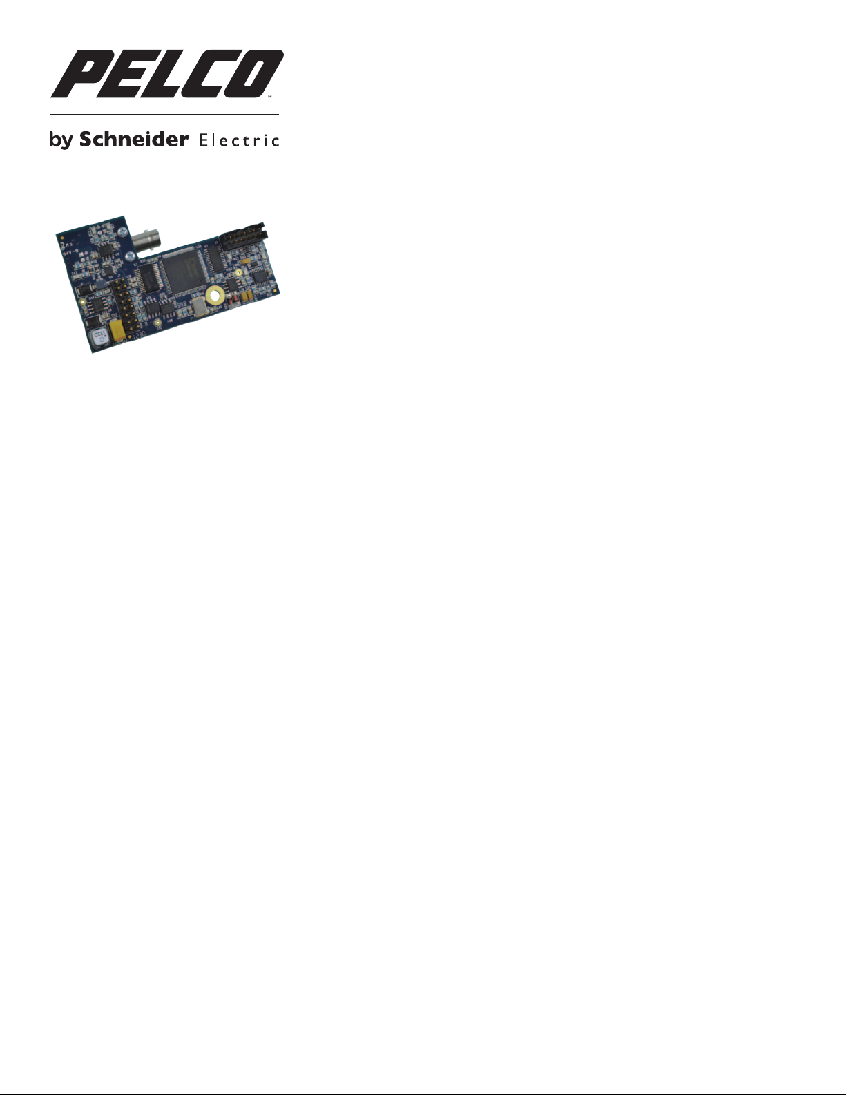
INSTALLATION AND OPERATION MANUAL
FSV10D1(M,S)1(ST,FC)
10-BIT DIGITAL VIDEO TRANSMITTER
WITH BIDIRECTIONAL RS422 OR COAXITRON®
UP-THE COAX DATA FOR PELCO™ DOME CAMERAS
The FSV10D1(M,S)1(ST,FC) series video transmitters and receivers support
simultaneous broadcast-quality video transmission of 10-bit digital video and
bidirectional RS422 data or Coaxitron® up-the-coax protocol, utilizing time-based
correction to achieve distances up to 69km (43mi), over one multimode or single mode
optical fiber. The transmitters are designed to plug directly into the Pelco Spectra® IV
dome, and connect with power, video input and two way data via the Pelco electrical
connector. See Figure 3 on Page 4 for in-dome installation instructions.
The receiver can be configured to communicate with the in-dome transmitter in RS422
or Coaxitron mode. See Figures 7 and 8 on Page 6 for configuration settings.
See Figures 1 – 8 for complete installation details.
Tech SupporT: (800) 289-9100 InTernaTIonal: +1 (559) 292-1981
C5632M / REV 11-06-12
Page 2

IMPORTANT SAFETY INSTRUCTIONS
1. Read these instructions.
2. Keep these instructions.
3. Heed all warnings.
4. Follow all instructions.
5. Do not use this apparatus near water.
6. Clean only with dry cloth.
7. Do not block any ventilation openings. Install in accordance with the manufacturer’s instructions.
8. Do not install near any heat sources such as radiators, heat registers, stoves, or other apparatus (including amplifiers) that produce heat.
9. Do not defeat the safety purpose of the polarized or grounding-type plug. A polarized plug has two blades with one wider than the other.
A grounding type plug has two blades and a third grounding prong. The wide blade or the third prong are provided for your safety. If the
provided plug does not fit into your outlet consult an electrician for replacement of the obsolete outlet.
10. Protect the power cord from being walked on or pinched particularly at plugs, convenience receptacles, and the points where they exit
from the apparatus.
11. Only use attachments/accessories specified by the manufacturer.
12. Use only with the cart, stand, tripod, bracket, or table specified by the manufacturer, or sold with the apparatus. When a cart is used, use
caution when moving the cart/apparatus combination to avoid injury from tip-over.
13. Refer all servicing to qualified service personnel. Servicing is required when the apparatus has been damaged in any way, such as
power-supply cord or plug is damaged, liquid has been spilled or objects have fallen into the apparatus, the apparatus has been exposed
to rain or moisture, does not operate normally, or has been dropped.
14. Apparatus shall not be exposed to dripping or splashing and that no objects filled with liquids, such as vases shall be placed on the
apparatus.
15. WARNING: To reduce the risk of fire or electric shock, do not expose this apparatus to rain or moisture.
16. Installation should be done only by qualified personnel and conform to all local codes.
17. Unless the unit is specifically marked as a NEMA Type 3, 3R, 3S, 4, 4X, 6, or 6P enclosure, it is designed for indoor use only and it must
not be installed where exposed to rain and moisture.
18. Use only installation methods and materials capable of supporting four times the maximum specified load.
19. A CCC-approved power cord must be used to power this equipment when used in China.
20. CAUTION: These servicing instructions are for use by qualified service personnel only. To reduce the risk of electric shock do not
perform any servicing other than that contained in the operating instructions unless you are qualified to do so.
The product and/or manual may bear the following marks:
This symbol indicates that dangerous voltage constituting a risk of electric shock is present within this unit.
This symbol indicates that there are important operating and maintenance instructions in the literature accompanying this unit.
CAUTION:
RISK OF ELECTRIC SHOCK.
DO NOT OPEN.
Tech SupporT: (800) 289-9100 InTernaTIonal: +1 (559) 292-1981 C5632M / REV 11-06-12
Page 3
INSTALLATION AND OPERATION MANUAL FSV10D1(M,S)1(ST,FC)
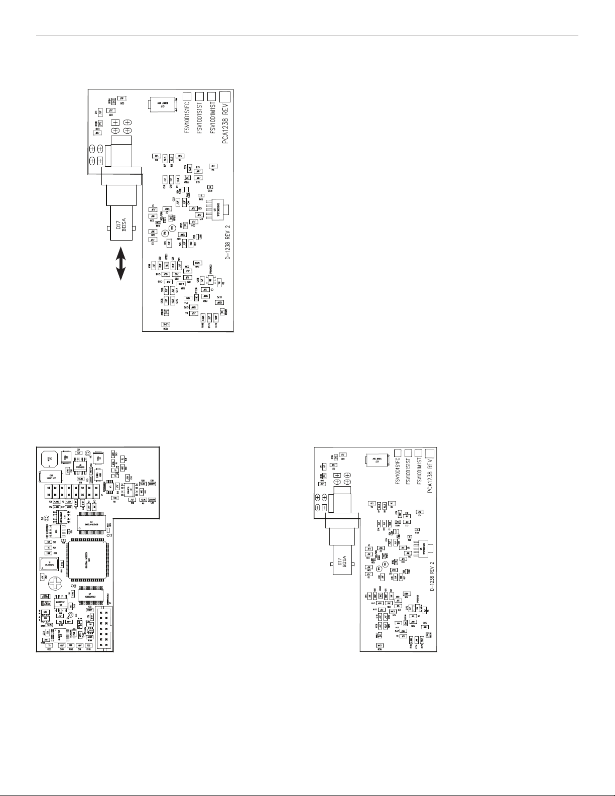
FIGURE 1 – TRANSMITTER
Each model includes one optical fiber cable as follows:
• FSV10D1M1ST – 13 inch multimode ST cable
• FSV10D1S1ST – 13 inch single mode ST cable
• FSV10D1S1FC – 13 inch single mode FC cable
MULTIMODE OR
SINGLE MODE
OPTICAL FIBER
FIGURE 2 – TRANSMITTER
BOTTOMTOP
Tech SupporT: (800) 289-9100 InTernaTIonal: +1 (559) 292-1981
C5632M / REV 11-06-12
Page 4

INSTALLATION AND OPERATION MANUAL FSV10D1(M,S)1(ST,FC)
FIGURE 3 – MOUNTING INSTRUCTIONS
See your Pelco Spectra IV Dome installation manual for details of dome installation.
Remove lower dome and dome drive from Spectra IV dome
according to the dome’s instruction manual to reveal the
back box (A).
A
E
B
C
D
Open the hinged door of Spectra IV back box to reveal the
circuit board (B).
Carefully move the power wiring to the left side of the circuit
board (B) as seen in this photo
Remove the plug from the 16-pin connector on the circuit
board (C).
Align the 16-pin connector on the dome circuit board
with its counterpart on the top of the FSV10S1 and plug
the header into the connector.
Using the supplied Phillips pan head screw with lock
washer, secure the transmitter into the mounting standoff
on the dome circuit board (D).
Connect the fiber optic connector on the transmitter to the
dome’s fiber optic adapter (E), and rate fiber optic cable.
Tech SupporT: (800) 289-9100 InTernaTIonal: +1 (559) 292-1981 C5632M / REV 11-06-12
Page 5

INSTALLATION AND OPERATION MANUAL FSV10D1(M,S)1(ST,FC)
FIGURE 3 – MOUNTING INSTRUCTIONS (CONT’D)
Route the power cord from the 24 volt power connector
away from the ber transmitter, as seen demonstrated by
the red and black wires here. Do not leave a “service loop”
of power cord in the back box. All slack wire should be
removed from the power cord.
If you are not installing alarm or relay connections, then
close the back box and replace the dome drive and lower
dome according to the dome’s instruction manual.
FIGURE 4 – INSTALLING ALARM AND RELAY WIRING
The Spectra allows for the use of alarms and relays
through the 13-pin connector on the left side of the dome
circuit board (G).
After attaching the alarm and relay wiring to this connector,
G
Tech SupporT: (800) 289-9100 InTernaTIonal: +1 (559) 292-1981
use the included plastic tie wraps to carefully gather the
alarm, relay and power wires into one bundle. Route that
bundle out of the Spectra back box on the left hand side,
away from the ber transmitter, as seen in this image. Do
not leave a “service loop” of power cord in the back box.
All slack wire should be removed from the power cord.
Close the back box and replace the dome drive and lower
dome according to the dome’s instruction manual.
Routing the power or the power and alarm and relay wires
in this manner increases the Spectra’s electromagnetic
compatibility. This will increase performance in electrically
“noisy” environments.
C5632M / REV 11-06-12
Page 6

MECHANICAL INSTALLATION INSTRUCTIONS
VIDEO
+
ON
LINK
OPTICAL
IN/OUT
VIDEOOUT
232485422
FIGURE 5 – LED INDICATORS (RECEIVER)
As displayed on FRV10D1(M,S)1(ST,FC) Receiver
LINK VIDEO DATA IN DATA OUT POWER
GREEN Communication link has
been established over
optical fiber
RED Communication link has not
been established.
OFF Unit powered down.
FIGURE 6 – LED INDICATORS (TRANSMITTER)
Visible when camera is not installed in dome, the back box board is swung down, the FSV10D1(M,S)1(ST,FC) is plugged in using the fiber optic
connector and the 16-pin connector in the dome circuit board and the back box is powered up.
Note: Selection of data format (RS-422 or Coaxitron) is made on receiver. The transmitter need not be configured.
LED LINK
BLINKING
GREEN
SOLID
RED Communication link has not been established.
OFF Unit powered down.
Communication link has been established over optical fiber and is
configured for Coaxitron communication
Communication link has been established over optical fiber and is
configured for RS-422 communication
An active video signal
is present on the BNC
connector.
– – – –
An active data signal is
present on the input pins of
the data connector.
An active data signal is
present on the output pins
of the data connector.
Unit powered up
FIGURE 7 – DATA CHANNEL CONNECTIONS
To be used on FRV10D1(M,S)1(ST,FC) Receiver
FIGURE 8 – SWITCH POSITIONS
As set on FRV10D1(M,S)1(ST,FC) Receiver
DATA
DOUT
12
1 2 1 2
DIN
GND
Data In (+)
Data In (–)
Data Out (+)
Data Out (–)
Switch
RS422 Coaxitron™
Up-the-Coax
DOUT+
DOUT-
DIN+
DIN-
A
B
INSTALLATION CONSIDERATIONS
This fiber-optic link is supplied as an in-dome mountable module. Units should be installed in dry locations protected from extremes of temperature
and humidity.
WARNING: Unit is to be used with a Listed Class 2 or LPS power supply.
IMPORTANT SAFEGUARDS:
A) Elevated Operating Ambient - If installed in a closed or multi-unit rack assembly, the operating ambient temperature of the rack environment may be greater
than room ambient. Therefore, consideration should be given to installing the equipment in an environment compatible with the maximum ambient temperature
(Tma) specified by the manufacturer.
B) Reduced Air Flow - I
Tech SupporT: (800) 289-9100 InTernaTIonal: +1 (559) 292-1981 C5632M / REV 11-06-12
nstallation of the equipment in a rack should be such that the amount of air flow required for safe operation of the equipment is not compromised.
Page 7

PRODUCT WARRANTY AND RETURN INFORMATION
WARRANTY
Pelco will repair or replace, without charge, any merchandise proved defective in
material or workmanship for a period of one year after the date of shipment.
Exceptions to this warranty are as noted below:
•Five years:
–Fiber optic products
– Unshielded Twisted Pair (UTP) transmission products
–CC3701H-2, CC3701H-2X, CC3751H-2, CC3651H-2X, MC3651H-2, and
MC3651H-2X camera models
• Three years:
–FD Series and BU Series analog camera models
–Fixed network cameras and network dome cameras with Sarix
–Sarix thermal imaging products (TI and ESTI Series)
–Fixed analog camera models (C20 Series, CCC1390H Series, C10DN Series,
and C10CH Series)
– EH1500 Series enclosures
–Spectra
–Spectra HD dome products
–Camclosure
®
IV products (including Spectra IV IP)
®
IS Series integrated camera systems
– DX Series video recorders (except DX9000 Series which is covered for a
period of one year), DVR5100 Series digital video recorders, Digital Sentry
Series hardware products, DVX Series digital video recorders, and NVR300
Series network video recorders
®
– Endura
– Genex
Series distributed network-based video products
®
Series products (multiplexers, server, and keyboard)
– PMCL200/300/400 Series LCD monitors
–PMCL5xxF Series and PMCL5xxNB Series LCD monitors
•Two years:
–Standard varifocal, fixed focal, and motorized zoom lenses
– DF5/DF8 Series fixed dome products
®
–Legacy
–Spectra III
Series integrated positioning systems
™
, Spectra Mini, Spectra Mini IP, Esprit®, ExSite®, ExSite IP, and
PS20 scanners, including when used in continuous motion applications
– Esprit Ti and TI2500 Series thermal imaging products
– Esprit and WW5700 Series window wiper (excluding wiper blades)
–CM6700/CM6800/CM9700 Series matrix
– Digital Light Processing (DLP
®
) displays (except lamp and color wheel). The
lamp and color wheel will be covered for a period of 90 days. The air filter is
not covered under warranty.
®
technology
•Six months:
– All pan and tilts, scanners, or preset lenses used in continuous motion
applications (preset scan, tour, and auto scan modes)
Pelco will warrant all replacement parts and repairs for 90 days from the date of
Pelco shipment. All goods requiring warranty repair shall be sent freight prepaid
to a Pelco designated location. Repairs made necessary by reason of misuse,
alteration, normal wear, or accident are not covered under this warranty.
Pelco assumes no risk and shall be subject to no liability for damages or loss
resulting from the specific use or application made of the Products. Pelco’s liability
for any claim, whether based on breach of contract, negligence, infringement of
any rights of any party or product liability, relating to the Products shall not exceed
the price paid by the Dealer to Pelco for such Products. In no event will Pelco be
liable for any special, incidental, or consequential damages (including loss of use,
loss of profit, and claims of third parties) however caused, whether by the
negligence of Pelco or otherwise.
The above warranty provides the Dealer with specific legal rights. The Dealer may
also have additional rights, which are subject to variation from state to state.
If a warranty repair is required, the Dealer must contact Pelco at (800) 289-9100 or
(559) 292-1981 to obtain a Repair Authorization
®
following information:
number (RA), and provide the
1. Model and serial number
2. Date of shipment, P. O. number, sales order number, or Pelco invoice number
3. Details of the defect or problem
If there is a dispute regarding the warranty of a product that does not fall under
the warranty conditions stated above, please include a written explanation with
the product when returned.
Method of return shipment shall be the same or equal to the method by which the
item was received by Pelco.
RETURNS
To expedite parts returned for repair or credit, please call Pelco at (800) 289-9100
or (559) 292-1981 to obtain an authorization number (CA number if returned for
credit, and RA number if returned for repair) and designated return location.
All merchandise returned for credit may be subject to a 20 percent restocking and
refurbishing charge.
Goods returned for repair or credit should be clearly identified with the assigned
CA or RA number and freight should be prepaid.
Revised 1-12-12
This equipment contains electrical or electronic components that must be recycled properly to comply with Directive 2002/96/EC of the European Union
regarding the disposal of waste electrical and electronic equipment (WEEE). Contact your local dealer for procedures for recycling this equipment.
Pelco, the Pelco logo, and other trademarks associated with Pelco products referred to in this publication are trademarks of Pe .cnI ,ocleP ,2102 thgirypoC © .setailiffa sti ro .cnI ,ocl
All other product names and services are the property of their respective companies. All rights reserved.
Product specifications and availability are subject to change without notice.
Page 8

www.pelco.com
Pelco by Schneider Electric 3500 Pelco Way Clovis, California 93612-5699 United States
USA & Canada Tel (800) 289-9100 Fax (800) 289-9150
International Tel +1 (559) 292-1981 Fax +1 (559) 348-1120
 Loading...