

Page 1
INSTALLATION
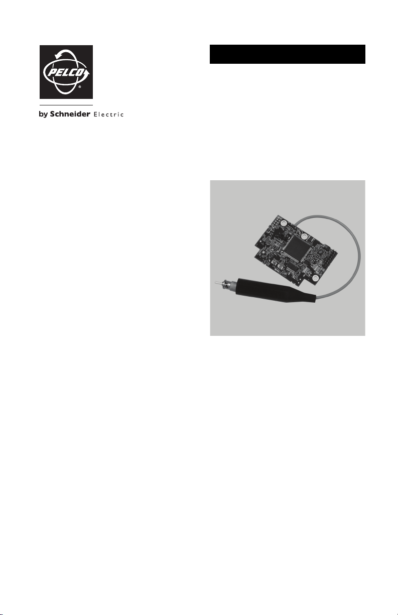
FS85011A Fiber Transmitter
Single-Channel Digitally Encoded Video
with Bidirectional Data
C2606M-A (6/09)
Page 2

Page 3

Contents
Important Safety Instructions. . . . . . . . . . . . . . . . . . . . . . . . . . . . . . . . . . . . . . . . . . . . . . . . . . . . . . . . . . . . . 5
Regulatory Notices. . . . . . . . . . . . . . . . . . . . . . . . . . . . . . . . . . . . . . . . . . . . . . . . . . . . . . . . . . . . . . . . . . . . . 6
Product Overview . . . . . . . . . . . . . . . . . . . . . . . . . . . . . . . . . . . . . . . . . . . . . . . . . . . . . . . . . . . . . . . . . . . . . . 7
Description . . . . . . . . . . . . . . . . . . . . . . . . . . . . . . . . . . . . . . . . . . . . . . . . . . . . . . . . . . . . . . . . . . . . . . 7
Models . . . . . . . . . . . . . . . . . . . . . . . . . . . . . . . . . . . . . . . . . . . . . . . . . . . . . . . . . . . . . . . . . . . . . . . . . 8
Top View . . . . . . . . . . . . . . . . . . . . . . . . . . . . . . . . . . . . . . . . . . . . . . . . . . . . . . . . . . . . . . . . . . . . . . . . 9
Bottom View. . . . . . . . . . . . . . . . . . . . . . . . . . . . . . . . . . . . . . . . . . . . . . . . . . . . . . . . . . . . . . . . . . . . 10
Installation . . . . . . . . . . . . . . . . . . . . . . . . . . . . . . . . . . . . . . . . . . . . . . . . . . . . . . . . . . . . . . . . . . . . . . . . . . 11
Package Contents. . . . . . . . . . . . . . . . . . . . . . . . . . . . . . . . . . . . . . . . . . . . . . . . . . . . . . . . . . . . . . . . 11
Data Communication Setup . . . . . . . . . . . . . . . . . . . . . . . . . . . . . . . . . . . . . . . . . . . . . . . . . . . . . . . . 11
Mounting . . . . . . . . . . . . . . . . . . . . . . . . . . . . . . . . . . . . . . . . . . . . . . . . . . . . . . . . . . . . . . . . . . . . . . 11
Troubleshooting . . . . . . . . . . . . . . . . . . . . . . . . . . . . . . . . . . . . . . . . . . . . . . . . . . . . . . . . . . . . . . . . . . . . . . 15
Specifications. . . . . . . . . . . . . . . . . . . . . . . . . . . . . . . . . . . . . . . . . . . . . . . . . . . . . . . . . . . . . . . . . . . . . . . . 17
C2606M-A (6/09) 3
Page 4

List of Illustrations
1 Single-Channel Video and RS-422 Application . . . . . . . . . . . . . . . . . . . . . . . . . . . . . . . . . . . . . . . . . . 7
2 Single-Channel Video and Coaxitron Data Application . . . . . . . . . . . . . . . . . . . . . . . . . . . . . . . . . . . . 7
3 Top View of FS85011A Transmitter . . . . . . . . . . . . . . . . . . . . . . . . . . . . . . . . . . . . . . . . . . . . . . . . . . . 9
4 Bottom View of FS85011A Transmitter . . . . . . . . . . . . . . . . . . . . . . . . . . . . . . . . . . . . . . . . . . . . . . . 10
5 Removing the Spectra III/Spectra IV Lower Dome and Dome Drive . . . . . . . . . . . . . . . . . . . . . . . . . 12
6 Opening the Door of the Spectra III/Spectra IV Back Box . . . . . . . . . . . . . . . . . . . . . . . . . . . . . . . . . 12
7 Routing Spectra III/Spectra IV Coaxial Cable . . . . . . . . . . . . . . . . . . . . . . . . . . . . . . . . . . . . . . . . . . 13
8 Spectra III/Spectra IV Circuit Board. . . . . . . . . . . . . . . . . . . . . . . . . . . . . . . . . . . . . . . . . . . . . . . . . . 13
4 C2606M-A (6/09)
Page 5

Important Safety Instructions
CAUTION:
RISK OF ELECTRIC SHOCK.
DO NOT OPEN.
1. Read these instructions.
2. Keep these instructions.
3. Heed all warnings.
4. Follow all instructions.
5. Do not use this apparatus near water.
6. Clean only with dry cloth.
7. Do not block any ventilation openings. Install in accordance with the manufacturer’s instructions.
8. Do not install near any heat sources such as radiators, heat registers, stoves, or other apparatus
(including amplifiers) that produce heat.
9. Do not defeat the safety purpose of the polarized or grounding-type plug. A polarized plug has two
blades with one wider than the other. A grounding plug has two blades and a third grounding prong.
The wide blade or the third prong are provided for your safety. If the provided plug does not fit into
your outlet consult an electrician for replacement of the obsolete outlet.
10. Protect the power cord from being walked on or pinched particularly at plugs, convenience
receptacles, and the points where they exit from the apparatus.
11. Only use attachments/accessories specified by the manufacturer.
12. Use only with the cart, stand, tripod, bracket, or table specified by the manufacturer, or sold with the
apparatus. When a cart is used, use caution when moving the cart/apparatus combination to avoid
injury from tip-over.
13. Refer all servicing to qualified service personnel. Servicing is required when the apparatus has been
damaged in any way, such as power-supply cord or plug is damaged, liquid has been spilled or
objects have fallen into the apparatus, the apparatus has been exposed to rain or moisture, does not
operate normally, or has been dropped.
14. Apparatus shall not be exposed to dripping or splashing and that no objects filled with liquids, such
as vases shall be placed on the apparatus.
15. WARNING: To reduce the risk of fire or electric shock, do not expose this apparatus to rain or
moisture.
16. Installation should be done only by qualified personnel and conform to all local codes.
17. Unless the unit is specifically marked as a NEMA Type 3, 3R, 3S, 4, 4X, 6, or 6P enclosure, it is
designed for indoor use only and it must not be installed where exposed to rain and moisture.
18. Use only installation methods and materials capable of supporting four times the maximum
specified load.
19. A CCC-approved power cord must be used to power this equipment when used in China.
20. CAUTION: These servicing instructions are for use by qualified service personnel only. To reduce
the risk of electric shock do not perform any servicing other than that contained in the operating
instructions unless you are qualified to do so.
The product and/or manual may bear the following marks:
This symbol indicates that dangerous voltage
constituting a risk of electric shock is present
within this unit.
This symbol indicates that there are important
operating and maintenance instructions in the
literature accompanying this unit.
C2606M-A (6/09) 5
Page 6

Regulatory Notices
This device complies with Part 15 of the FCC Rules. Operation is subject to the following two conditions:
(1) this device may not cause harmful interference, and (2) this device must accept any interference
received, including interference that may cause undesired operation.
Radio And Television Interference
This equipment has been tested and found to comply with the limits of a Class A digital device, pursuant
to Part 15 of the FCC Rules. These limits are designed to provide reasonable protection against harmful
interference when the equipment is operated in a commercial environment. This equipment generates,
uses, and can radiate radio frequency energy and, if not installed and used in accordance with the
instruction manual, may cause harmful interference to radio communications. Operation of this equipment
in a residential area is likely to cause harmful interference in which case the user will be required to
correct the interference at his own expense.
Changes and Modifications not expressly approved by the manufacturer or registrant of this equipment
can void your authority to operate this equipment under Federal Communications Commission’s rules.
This Class A digital apparatus complies with Canadian ICES-003.
Cet appareil numérique de la classe A est conforme à la norme NMB-003 du Canada.
6 C2606M-A (6/09)
Page 7

Product Overview
ONE
VIDEO
OUTPUT
RS-422
DATA
FR85011A
RECEIVER
SPECTRA III /
SPECTRA IV
DOME
FS85011A
TRANSMITTER
ONE FIBER
DESCRIPTION
The FS85011A fiber transmitter is designed for quick and easy installation into the back box of Spectra III™
and Spectra
NOTE: The FS85011A transmitter can also be included as part of an ExSite
system at the factory.
Compatible with the FR85011A/FR85011 receiver, the FS85011A transmitter provides the ability to send
one unidirectional composite video channel and one bidirectional RS-422 data channel over one optical
fiber (refer to Figure 1). In addition, patent-pending technology provides the solution for allowing
Coaxitron
2).
®
IV domes.
™
explosionproof positioning
®
pan/tilt/zoom (PTZ) control data to be transmitted the full distance of the fiber (refer to Figure
Figure 1. Single-Channel Video and RS-422 Application
ONE
VIDEO
OUTPUT
COAXITRON
DATA
FS85011A
TRANSMITTER
SPECTRA III /
SPECTRA IV
DOME
ONE FIBER
FR85011A
RECEIVER
Figure 2. Single-Channel Video and Coaxitron Data Application
C2606M-A (6/09) 7
Page 8

Features of the FS85011A fiber optic transmission system include the following:
• Eight-bit digitally encoded video for high-quality video transmission over a single fiber
• Bidirectional RS-422 data channel or Coaxitron communication
• Integrated wavelength division multiplexing (WDM), allowing video and data channels to be
transmitted in the same optical fiber using different wavelengths
• Multimode fiber support for distances up to 6 km (3.7 mi)
• Single-mode fiber support for distances up to 46 km (28.6 mi)
• Laser diode for transmission of optical signals
• Exceeds all requirements for the RS-250C Medium-Haul Transmission specification
• Compatible with NTSC, PAL, and SECAM video standards
• No performance adjustments required
• LED indicator for monitoring of signal status
In addition, note the following information:
• The FS85011A transmitter is a Class 1 laser product that complies with FDA radiation performance
standard 21CFR Subchapter J and with IEC 60825-1 Edition 1.2, 2001-08.
• For optical power budget and maximum transmission distance specifications of the FS85011A
transmitter when used with the FR85011A/FR85011 receiver, refer to Specifications on page 17. For
additional information about the FR85011A/FR85011 receiver, refer to the manual supplied with the
receiver.
MODELS
The FS85011A transmitter consists of the following series of models:
Multimode Models:
FS85011AMST Single-channel fiber optic video transmitter/data transceiver; multimode,
FS85011AMSTEX Single-channel fiber optic video transmitter/data transceiver; multimode,
Single-Mode Models:
FS85011ASST Single-channel fiber optic video transmitter/data transceiver; single-mode,
FS85011ASSTEX Single-channel fiber optic video transmitter/data transceiver; single-mode,
FS85011ASFC Single-channel fiber optic video transmitter/data transceiver; single-mode,
ST connector; 6 inch (15.24 cm) cable; compatible with FR85011AMSTR and
FR85011MSTR receivers
ST connector; 6 ft (1.83 m) cable; compatible with FR85011AMSTR and
FR85011MSTR receivers
ST connector; 6 inch (15.24 cm) cable; compatible with FR85011ASSTR and
FR85011SSTR receivers
ST connector; 6 ft (1.83 m) cable; compatible with FR85011ASSTR and FR85011SSTR
receivers
FC connector; 6 inch (15.24 cm) cable; compatible with FR85011ASFCR and
FR85011SFCR receivers
8 C2606M-A (6/09)
Page 9
TOP VIEW
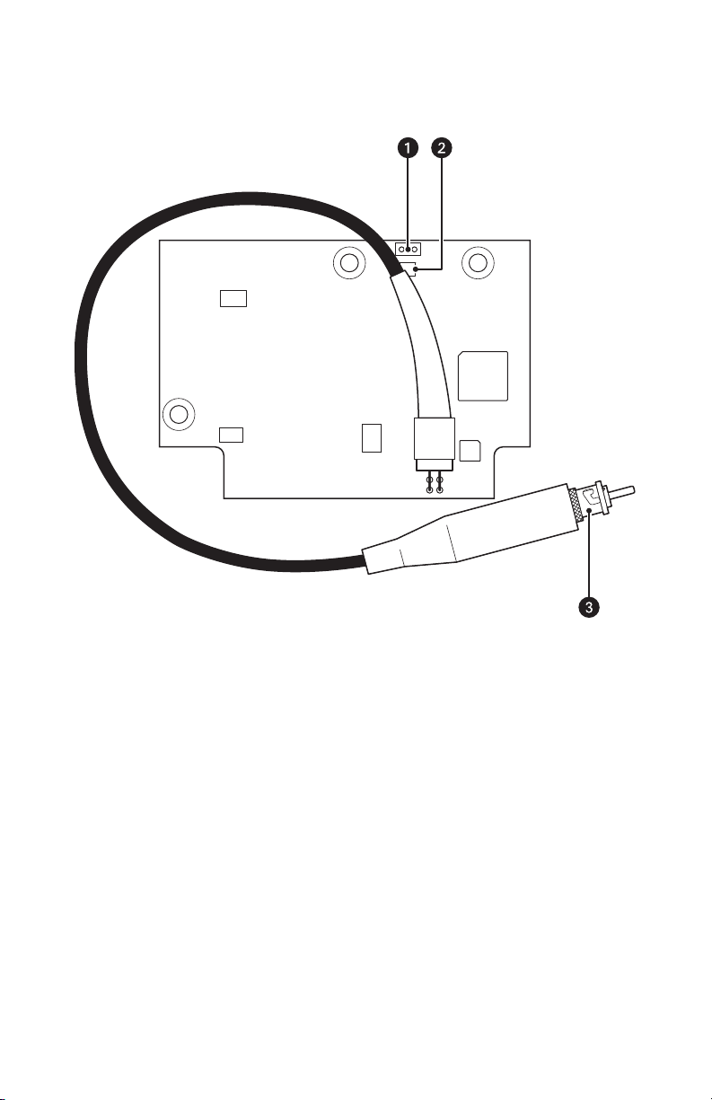
Figure 3 illustrates the top of the FS85011A transmitter.
Figure 3. Top View of FS85011A Transmitter
ì
Data Selection Connector (P3): A 2-pin header; removable mating plug (not shown).
î
Optic Fault LED (CR1): Refer to Troubleshooting on page 15 for detailed information.
ï
Fiber Optic Connector: ST or FC (model dependent).
C2606M-A (6/09) 9
Page 10

BOTTOM VIEW
Figure 4 illustrates the bottom of the FS85011A transmitter.
Figure 4. Bottom View of FS85011A Transmitter
Power, Video, and Data Connector (P1): A 16-pin header.
ì
P1
10 C2606M-A (6/09)
Page 11

Installation
PACKAGE CONTENTS
The following items are supplied:
1 FS85011A transmitter
1 Fiber optic adapter (depending on model):
• ST to ST adapter for FS85011AMST transmitter
• FC to ST adapter for FS85011ASST transmitter
• FC to FC adapter for FS85011ASFC transmitter
1 Screw with lock washer, 4-40 x 0.250-inch, Phillips pan head
1 FS85011A Fiber Transmitter Installation manual
DATA COMMUNICATION SETUP
The FS85011A transmitter supports RS-422 and Coaxitron data communication. The default setting is
RS-422.
NOTE: Determine the required data communication and, if necessary, change the data communication
setting of the FS85011A transmitter before installing the transmitter into the Spectra III/Spectra IV back
box.
WARNING: When setting data communication on the FS85011A transmitter, prevent electrostatic
discharge (ESD) damage to the transmitter by wearing a grounding wrist strap that is connected to
an approved grounding source.
The Data Selection connector (2-pin header), which is located on the top of the FS85011A transmitter
(refer to Figure 3 on page 9), allows you to set the data communication required for the transfer of data.
Set data communication to either of the following types:
• RS-422: Enabled when the 2-pin header plug is connected to the header (default setting).
• Coaxitron: Enabled when the 2-pin header plug is not connected to the header. If Coaxitron is
required, remove the plug from the 2-pin header.
MOUNTING
The FS85011A transmitter mounts to the circuit board inside the Spectra III/Spectra IV back box.
NOTE: Before mounting the FS85011A transmitter, determine the required data communication and, if
necessary, change the setting of the transmitter (refer to Data Communication Setup for information).
WARNING: When mounting the FS85011A transmitter, prevent electrostatic discharge (ESD)
damage to the transmitter by wearing a grounding wrist strap that is connected to an approved
grounding source.
C2606M-A (6/09) 11
Page 12

To mount the transmitter into an existing or new Spectra III/Spectra IV installation:
1. (Existing Spectra III/Spectra IV installatio n o nly ) Perform the following steps:
a. Turn off power to the dome.
b. Remove the lower dome (refer to Figure 5A).
c. Remove the dome drive from the back box (refer to Figure 5B).
A. LOWER DOME REMOVAL B. DOME DRIVE REMOVAL
Figure 5. Removing the Spectra III/Spectra IV Lower Dome and Dome Drive
2. Open the hinged door of the back box by pushing the tab lock toward the wall of the back box and
then pulling the door open (refer to Figure 6).
Figure 6. Opening the Door of the Spectra III/Spectra IV Back Box
3. (New Spectra III/Spectra IV installation only) Route the BNC connector and coaxial cable through the
wiring entrance at the rear of the back box to provide clearance for mounting the FS85011A
transmitter to the Spectra III/Spectra IV circuit board (refer to Figure 7 on page 13).
NOTE: The BNC connector is enclosed in an insulating boot. When routing the BNC connector,
ensure that the connector remains enclosed in the boot.
12 C2606M-A (6/09)
Page 13

WIRING ENTRANCE
COAXIAL CABLE
Figure 7. Routing Spectra III/Spectra IV Coaxial Cable
4. If necessary, reposition power wiring of the Spectra III/Spectra IV circuit board to provide clearance
for mounting the FS85011A transmitter to the circuit board.
WARNING: Improper handling of the power wiring can damage the wiring. Care should be taken
when repositioning the wiring.
5. Remove the plug from the 16-pin connector on the Spectra III/Spectra IV circuit board (refer to Figure 8).
RX-
RX+
TX-
TX+
1
2
3
4
5
6
7
GND
RELAYS
AUX2
GND
16-PIN
CONNECTOR
MOUNTING
STANDOFF
Figure 8. Spectra III/Spectra IV Circuit Board
6. Ensure that the fiber optic cable on the FS85011A transmitter is positioned to the left of the Data
Selection connector (refer to Top View on page 9).
7. Align the 16-pin header located on the bottom of the FS85011A transmitter with the 16-pin
connector on the Spectra III/Spectra IV circuit board, and then plug the header into the connector.
8. Secure the FS85011A transmitter to the mounting standoff on the Spectra III/Spectra IV circuit board
(refer to Figure 8) using the Phillips pan head screw with lock washer (supplied).
9. Connect the fiber optic connector on the FS85011A transmitter to the fiber optic adapter (supplied).
10. Connect the fiber optic adapter to the fiber optic cable at the rear of the Spectra III/Spectra IV back
box.
C2606M-A (6/09) 13
Page 14

11. Carefully close the door of the back box.
WARNING: When closing the door of the back box, be careful not to pinch or kink the fiber.
12. (Existing Spectra III/Spectra IV installation only) Perform the following steps:
a. Reinstall the dome drive into the back box.
b. Reinstall the lower dome.
c. Turn on power to the dome.
13. (New Spectra III/Spectra IV installation only) Refer to the Spectra III/Spectra IV installation
documentation for dome installation instructions.
NOTE: Power to the FS85011A transmitter is supplied from the Spectra III/Spectra IV dome.
14 C2606M-A (6/09)
Page 15

Troubleshooting
The Optic Fault (CR1) LED indicator on the top of the FS85011A transmitter allows you to monitor signal
status. Table A provides information about the indicator and associated troubleshooting guidelines.
If the following instructions fail to solve your problem, contact Pelco Product Support at 1-800-289-9100
(USA and Canada) or +1-559-292-1981 (International) for assistance. You should have the product serial
number available when calling.
Do not try to repair the unit yourself. Leave all maintenance and repairs to qualified technical personnel.
Table A. Troubleshooting with the Optic Fault Indicator (1 of 2)
Indicator Color Meaning Possible Cause Corrective Action
Green The optical signal is
being received and laser
is operating properly.
Red The optical signal is not
being received.
— No action required.
Remote fiber module is
not powered on.
Fiber optic cable is not
connected.
Fiber optic cable
connectors are dirty or
are damaged.
Fiber optic cable is
defective.
Optical dB losses in the
fiber optic installation
exceed the optical
power budget
specification stated in
Specifications on
page 17.
Optical dB losses in the
fiber optic installation
meet the optical power
budget specification
stated in Specifications
on page 17; however, a
fiber module is
defective.
Check power connections.
Replace power supply, if
necessary.
Check fiber optic connections.
Clean, polish, or replace fiber
optic cable connectors as
necessary.
Replace cable.
Check for problems with the
fiber optic installation, for
example, excessive dB losses
in connectors, splices, patch
panels, cables, and so forth.
Contact Product Support at
1-800-289-9100.
C2606M-A (6/09) 15
Page 16

Table A. Troubleshooting with the Optic Fault Indicator (2 of 2)
Indicator Color Meaning Possible Cause Corrective Action
Flashing red Laser has shut down. Fiber module is
operating in extreme
environmental
conditions; for example,
operating temperature is
Ensure that fiber module
operates according to
operating conditions stated in
Specifications, and then cycle
the power.
below or above
recommended range as
stated in Specifications
on page 17.
Laser has reached end of
Cycle the power.
life.
Not lit Power is not being
applied to the
transmitter.
Power connection is
faulty.
Check power connections to
the Spectra III/Spectra IV
dome.
16 C2606M-A (6/09)
Page 17

Specifications
VIDEO
Number of Channels 1
Modulation Type Pulse code modulation, 8-bit resolution
Video Input 1.0 Vp-p, 75 ohms; NTSC, PAL, and SECAM
Bandwidth 6.5 MHz
Gain Unity
Differential Gain <2%
Differential Phase <1°
Tilt <1%
Signal-to-Noise Ratio >60 dB (CCIR weighted)
DATA
Number of Channels 1
Data Communication RS-422, Coaxitron
GENERAL
Operating Temperature Refer to the Spectra III, Spectra IV, or ExSite product specifications
Input Power Requirements 12 VDC, 160 mA
LED Indicator Optic Fault
Dimensions 2.9” L x 2.0” W
Unit Weight 0.08 lb (0.04 kg)
as appropriate.
(7.37 x 5.08 cm)
MECHANICAL
Connectors
Video/Data/Power 16-pin header
Data Selection 2-pin header
Fiber Optic ST for multimode fiber
C2606M-A (6/09) 17
ST or FC for single-mode fiber
Page 18

OPTICAL POWER BUDGET, TRANSMISSION DISTANCE, AND LASER CLASS 1 LIMIT
The materials used in the manufacture of this document and its components are compliant to the requirements of
Directive 2002/95/EC.
This equipment contains electrical or electronic components that must be recycled properly to comply with
Directive 2002/96/EC of the European Union regarding the disposal of waste electrical and electronic
equipment (WEEE). Contact your local dealer for procedures for recycling this equipment.
REVISION HISTORY
Manual # Date Comments
C2606M 8/07 Original version.
C2606M-A 6/09 Added FS85011ASSTEX and FS85011AMSTEX models.
Pelco, the Pelco logo, Camclosure, Digital Sen try, Endura, Esprit, ExSite, Genex, Intelli-M, Legacy, and Spectra are registered trademarks of Pelco, Inc.
Spectra III is a trademark of Pelco, Inc.
DLP is a registered trademark of Texas Instruments Incorporated.
All product names and services identifi ed throughout this document are trademarks or registered trademarks of their resp ective companies.
The absence of a trademark or register ed trademark from this document does not constitute a waiver of intellectual property rights.
© Copyright 2009, Pelco, Inc. All rights reserved.
Model Number
FS85011A
Transmitter
Compatible
Receiver*
Wavelength
(Video/Data)
Optical
Power
Budget
Maximum
Transmission
Distance Cable Length
Multimode (62.5/125 µm)
†
FS85011AMST FR85011AMSTR 1310/850 nm 26 dB
FR85011MSTR 1310/850 nm 20 dB
FS85011AMSTEX FR85011AMSTR 1310/850 nm 26 dB
FR85011MSTR 1310/850 nm 20 dB
6 km (3.7 mi)‡6 inches (15.24 cm)
†
6 km (3.7 mi)‡6 inches (15.24 cm)
†
†
6 km (3.7 mi)
6 km (3.7 mi)
‡
‡
6 ft (1.83 m)
6 ft (1.83 m)
Single-Mode (9/125 µm)
§
FS85011ASST FR85011ASSTR 1310/1550 nm 28 dB 46 km (28.6 mi)
FR85011SSTR 1310/1550 nm 20 dB 30 km (18.6 mi)
FS85011ASSTEX FR85011ASSTR 1310/1550 nm 28 dB 46 km (28.6 mi)
FR85011SSTR 1310/1550 nm 20 dB 30 km (18.6 mi)
FS85011ASFC FR85011ASFCR 1310/1550 nm 28 dB 46 km (28.6 mi)
FR85011SFCR 1310/1550 nm 20 dB 30 km (18.6 mi)
*Single-channel fiber optic video receiver/data transceiver.
†
When using 50/125 µm multimode fiber, subtract 3 dB from the optical power budget.
‡
Maximum transmission distance is limited by fiber bandwidth.
§
Maximum transmission distance is based on attenuation of 0.5 dB/km plus a 5 dB buffer for connector and
6 inches (15.24 cm)
§
6 inches (15.24 cm)
§
6 ft (1.83 m)
§
6 ft (1.83 m)
§
6 inches (15.24 cm)
§
6 inches (15.24 cm)
splice losses.
Note: For models with higher optical power budgets, contact the factory.
18 C2606M-A (6/09)
Page 19

PRODUCT WARRANTY AND RETURN INFORMATION
WARRANTY
Pelco will repair or replace, without charge, an y merchandise proved defective in material or workmanship for a period of one year after the date of
shipment.
Exceptions to this warranty are as noted below:
• Five years:
– Fiber optic products
– TW3 000 Series unshielded twisted pair (UTP) transmission products
– CC370 1H-2, CC3701H-2X, CC3751H-2, CC3651H-2X, MC3651H-2, and MC3651H-2X camera models
• Three years:
– Pe lco-branded fixed camera models (CCC1390H Series, C10DN Series, C10CH Series, IP3701H Series, and IX Series)
– EH150 0 Series enclosures
®
– Spectra
IV products (including Spectra IV IP)
– Cam closure
– DX Se ries digital video recorders, DVR5100 Series digital video recorders, Digital Sentry
– En dura
– Ge nex® Series products (multiplexers, server, and keyboard)
– PMCL200/300/400 Series LCD monitors
• Two years:
– S tandard varifocal, fixed focal, and motorized zoom lenses.
– DF5/DF8 Series fixed dom e products
– Lega cy® Series integrated positioning systems
– Spectra III™, Spectra Mini, Spectra Mini IP, Esprit®, ExSite®, and PS20 scanners, including when u sed in continuous motion applications.
– Espr it Ti and TI2500 Series thermal imaging products
– Espr it and WW5700 Series window wiper (excluding wiper blades).
– CM 6700/CM6800/CM9700 Series matrix
– Di gital Light Processing (DLP®) displays (except lamp and color wheel). The lamp and color wheel will be covered for a period of 90 days.
– Inte lli-M
•One year:
– Video cassette record ers (VCRs), except video heads. Video heads will be covered for a period of six months.
• Six months:
– Al l pan and tilts, scanners, or preset lenses used in continuous motion applicatio ns (preset scan, tour, and auto scan modes).
Pelco will warrant all replacement parts and repairs for 90 days from the date of Pelco shipment. All goods requiring warranty repair shall be sent
freight prepaid to a Pelco designated locatio n. Repairs made necessary by reason of misuse, alteration, normal wear, or accident are no t covered under
this warranty.
Pelco assumes no risk and shall be subject to no li ability for damages or loss resulting from the specific use or application made of the Products.
Pelco’s liability for any claim, whether based on breach of contract, negligence, infringement of any rights of any party or product liability, relating to
the Products shall not exceed the price paid by the Dealer to Pelco for such Products. In no event will Pelco be liable for any special, incidental, or
consequential damages (including loss of use, loss of profit, and claims of third parties) however caused, whether by the negligence of Pelco or
otherwise.
The above warranty provides the Dealer with spe cific legal rights. The Dealer may also have additional right s, which are subject to variation from state
to state.
If a warranty repair is required, the Dealer must contact Pelco at (800 ) 289-9100 or (559) 292-1981 to obtain a Repair Authorization number (RA), and
provide the following information:
1. Model and serial number
2. Date of shipment, P.O. number, sales order number, or Pelco invoice number
3. Details of the defect or problem
If there is a dispute regarding the warranty of a product that does not fall un der the warranty conditions stated above, please include a written
explanation with the product wh en returned.
Method of return shipment shall be the same or equal to the method by which the item was received by Pelco.
RETURNS
To expedite parts returned for repair or credit, please call Pelco at (800) 289-9100 or (559) 292-1981 to obtain an authorization number (CA number if
returned for credit, and RA number if returned for repair) and designated return location.
All merchandise returned for credit may be subject to a 20 percent restocking and refurbishing charge.
Goods returned for repair or credit should be clearly identified with the assigned CA or RA number and freight should be prepaid
®
Series (IS, ICS, IP) integrated camera systems
recorders, and NVR300 Series network video r ecorders
®
Series distributed network-based video pro ducts
The air filter is not covered under warranty.
®
eIDC controllers
®
Series hardware products, DVX Series digital vide o
12-23-08
Page 20

www.pelco.com
Pelco, Inc. Worldwide Headquarters 3500 Pelco Way Clovis, California 93612 USA
USA & Canada Tel (800) 289-9100 Fax (800) 289-9150
International Tel +1 (559) 292-1981 Fax +1 (559) 348-1120
 Loading...