

Page 1
INSTALLATION
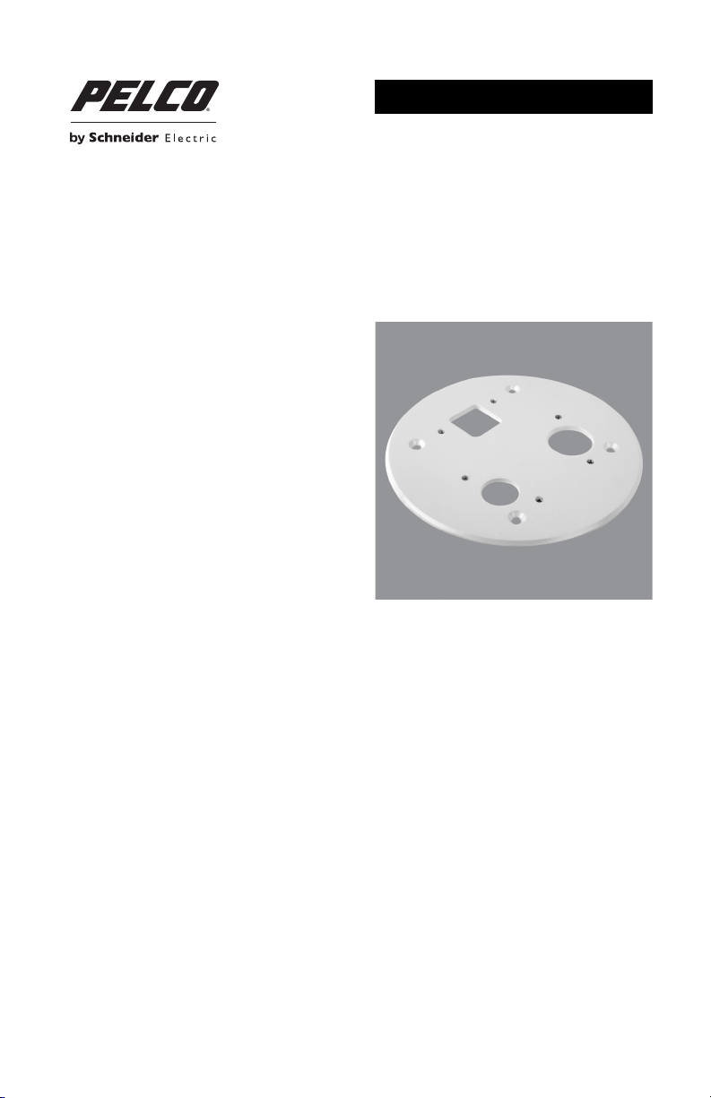
FD-AP Gangbox Adapter Plate
For FD2 and FD5 Series Cameras
C3969M (2/14)
Page 2

2 C3969M (2/14)
Page 3

Contents
Important Safety Instructions. . . . . . . . . . . . . . . . . . . . . . . . . . . . . . . . . . . . . . . . . . . . . . . . . . . . . . . . . . . . . 4
Description . . . . . . . . . . . . . . . . . . . . . . . . . . . . . . . . . . . . . . . . . . . . . . . . . . . . . . . . . . . . . . . . . . . . . . . . . . . 5
Parts List. . . . . . . . . . . . . . . . . . . . . . . . . . . . . . . . . . . . . . . . . . . . . . . . . . . . . . . . . . . . . . . . . . . . . . . . 5
User Supplied Parts and Tools List. . . . . . . . . . . . . . . . . . . . . . . . . . . . . . . . . . . . . . . . . . . . . . . . . . . . 5
Installation . . . . . . . . . . . . . . . . . . . . . . . . . . . . . . . . . . . . . . . . . . . . . . . . . . . . . . . . . . . . . . . . . . . . . . . . . . . 6
FD2 Series . . . . . . . . . . . . . . . . . . . . . . . . . . . . . . . . . . . . . . . . . . . . . . . . . . . . . . . . . . . . . . . . . . . . . . 6
FD5 Series . . . . . . . . . . . . . . . . . . . . . . . . . . . . . . . . . . . . . . . . . . . . . . . . . . . . . . . . . . . . . . . . . . . . . . 8
Specifications. . . . . . . . . . . . . . . . . . . . . . . . . . . . . . . . . . . . . . . . . . . . . . . . . . . . . . . . . . . . . . . . . . . . . . . . 10
C3969M (2/14) 3
Page 4

Important Safety Instructions
1. Read these instructions.
2. Keep these instructions.
3. Heed all warnings.
4. Follow all instructions.
5. Only use attachments/accessories specified by the manufacturer.
6. Installation should be done only by qualified personnel and conform to all local codes.
7. Use only installation methods and materials capable of supporting four times the maximum
specified load.
8. Only use replacement parts recommended by Pelco.
4 C3969M (2/14)
Page 5

Description
The FD-AP gangbox adapter plate is specifically designed for use with FD2 Series indoor and FD5 Series
outdoor dome cameras.
PARTS LIST
The following parts are supplied.
Qty Description
1 FD-AP gangbox adapter plate
4 Screws (white), 8-32 x 0.75-inch, flat head, with washers and nuts
4 Screws, 8-32 x 0.5-inch, pan head
USER SUPPLIED PARTS AND TOOLS LIST
The following installation parts and tools are needed but not supplied.
Qty Description
1 FD2 or FD5 Series dome camera
1 T20 Torx wrench
1 Flat-head screwdriver
1 #2 Phillips screwdriver
1 4S electrical outlet box
C3969M (2/14) 5
Page 6

Installation
Install the gangbox adapter plate to the electrical outlet box and your FD2 or FD5 camera according to one
of the following procedures. Use the supplied parts provided in the product box and other tools required for
your model as suggested in the User Supplied Parts and Tools List on page 5.
FD2 SERIES
1. Attach the FD-AP gangbox adapter plate to a 4S electrical outlet box (not supplied).
a. Install two of the 8-32 x 0.75-inch flat head screws. Secure them to the adapter plate with the
washers and nuts.
b. Pull the system video, power, and alarm wires through the square opening in the adapter
plate.
c. Attach the adapter plate to the corresponding holes in the electrical outlet box with the two
remaining 8-32 x 0.75-inch flat head screws (supplied).
Figure 1. Installing the Adapter Plate and the FD2 Series Camera
ì
Electrical Outlet Box
î
Adapter Plate
ï
FD2 Series Camera
ñ
Dome Cover
6 C3969M (2/14)
Page 7

2. Attach the camera to the gangbox adapter plate:
a. Remove the dome cover to prepare the camera for installation. Refer to the
installation/operation manual supplied with the FD2 Series camera for instructions.
b. Connect the camera video, power, and alarm wires to the camera. Refer to the
installation/operation manual supplied with the FD2 Series camera for wiring instructions.
c. Align the indentation on the camera with the square opening in the adapter plate.
Figure 2. Indentation on Camera
d. Feed the camera wiring through the conduit indentation on the camera.
e. Connect the camera and system wiring above the adapter plate.
f. Attach the camera to the adapter plate with two 8-32 x 0.5-inch pan head screws (supplied).
Figure 3. Alignment and Attachment Points on Adapter Plate
ì
Opening for FD2 Wiring
î
Camera Attachment Points
3. Complete the installation. Refer to the installation/operation manual supplied with the FD2 Series
camera for more information.
C3969M (2/14) 7
Page 8

FD5 SERIES
1. Attach the FD-AP gangbox adapter plate to a 4S electrical outlet box (not supplied).
a. Install two of the 8-32 x 0.75-inch flat head screws. Secure them to the adapter plate with the
washers and nuts.
b. Pull the system video, power, and alarm wires through the smaller of the two round openings
in the adapter plate.
c. Attach the adapter plate to the corresponding holes in the electrical outlet box with the two
remaining 8-32 x 0.75-inch flat head screws (supplied).
Figure 4. Installing the Adapter Plate and FD5 Series Camera
ì
Electrical Outlet Box
î
Adapter Plate
ï
FD5 Series Camera
ñ
Dome Cover
8 C3969M (2/14)
Page 9

2. Attach the camera to the gangbox adapter plate:
a. Remove the dome cover to prepare the camera for installation. Refer to the
installation/operation manual supplied with the FD5 Series camera for instructions.
b. Connect the camera video, power, and alarm wires to the camera. Refer to the
installation/operation manual supplied with the FD5 Series camera for wiring instructions.
c. Align the smaller circular opening in the adapter plate with the sealed waterproof cable plug
in the camera base.
Figure 5. Alignment and Attachment Points for the Adapter Plate and FD5 Camera
ì
Opening for FD5 Wiring
î
Camera Attachment Points
ï
FD5 Series Sealed Waterproof Cable Plug
d. Feed the camera wiring from the cable plug through the circular opening in the adapter plate.
e. Connect the camera and system wiring above the adapter plate.
f. Attach the camera to the adapter plate with the four 8-32 x 0.5-inch pan head screws
(supplied).
3. Complete the installation. Refer to the installation/operation manual supplied with the FD5 Series
camera for more information.
C3969M (2/14) 9
Page 10

Specifications
MODEL
FD-AP Gangbox adapter plate, designed for use with FD2 and FD5 Series
GENERAL
Construction Aluminum
Finish White polyester powder coat
Unit Weight 0.16 kg (0.35 lb)
NOTE: VALUES IN PARENTHESES ARE INCHES; ALL OTHERS ARE CENTIMETERS.
dome cameras
10 C3969M (2/14)
Page 11

WARRANTY STATEMENT
For information about Pelco’s product warranty and thereto related information, refer to www.pelco.com/warranty.
This equipment contains electrical or electronic components that must be recycled properly to comply with Directive
2002/96/EC of the European Union regarding the disposal of waste electrical and electronic equipment (WEEE).
Contact your local dealer for procedures for recycling this equipment.
REVISION HISTORY
Manual # Date Comments
C3969M 2/14 Original version.
Pelco, the Pelco logo, and other trademarks a ssociated with Pelco products referred to in this publication are trademarks of P elco, Inc. or its affiliates.
All other product names and services are th e property of their respective companies. ONVIF and the ONVIF logo are trademarks of ONVIF Inc.
Product specifications and availability are subject to change without notice. © Copyright 2014, Pelco, Inc. All rights re served.
Page 12

Pelco by Schneider Electric 3500 Pelco Way Clovis, California 93612-5699 United States
USA & Canada Tel (800) 289-9100 Fax (800) 289-9150
International Tel +1 (559) 292-1981 Fax +1 (559) 348-1120
www.pelco.com www.pelco.com/community
 Loading...