

Page 1
EN_C3970M (05/14)
FD5 Series 65 0 TV lines
Ruggedized/Outdoor Dome Camera
Installation/Operation Manual
18 to 32 VAC (Revision A)
Before attempting to connect or operate this product, please read these instructions
carefully and save this man ual f or fu tur e use.
FD5 series model names:
FD5-V9-6(X)
FD5-DV10-6(X)
FD5-IRV10-6(X)
FD5-DWV10-6(X)
FD5-DWV22-6(X)
1
Page 2

CONTENTS
CONTENTS
Important Safety I nstructions ................................................................................................................................... 4
REGULATORY NO T ICES [FCC CLASS B] ........................................................................................................... 5
Warranty .............................................................................................................................................................. 6
1. Introduction ............................................................................................................................................................. 7
1.1 Before You Begin ........................................................................................................................................ 7
1.2 Package Contents ....................................................................................................................................... 7
1.3 Optional Accessories .................................................................................................................................. 7
1.4 Dimensions .................................................................................................................................................. 7
1.5 Names of Camera Par ts ............................................................................................................................. 8
1.6 Routine Maintenance .................................................................................................................................. 8
2. Installation .............................................................................................................................................................. 9
2.1 Disassembling the Camera ....................................................................................................................... 9
2.2 Installing the Waterproof Plug ................................................................................................................. 10
2.3 Connecting the Wiring .............................................................................................................................. 10
2.4 Mounting the Camera ............................................................................................................................... 10
2.5 Optional Camera Setti ngs ........................................................................................................................ 13
2.6 Adj us t i ng t he Camera Position ................................................................................................................ 14
2.7 Adj us t i ng t he Lens (if equipped with vari-focal lens) ............................................................................ 14
2.8 Completing the Installation ...................................................................................................................... 15
2.9 General Help for Waterproof Plug Installation ...................................................................................... 16
3. OSD Menu ............................................................................................................................................................ 18
4. OSD Menu Settings ............................................................................................................................................ 20
4.1(A) LENS...................................................................................................................................................... 21
4.2(A) SHUTTER/AGC ................................................................................................................................... 21
4.3(A) WHITE BAL .......................................................................................................................................... 22
4.4(A) BACKLIGHT ......................................................................................................................................... 23
4.5(A) PICTU RE ADJ US T .............................................................................................................................. 23
4.6(A) ATR* ...................................................................................................................................................... 23
4.7(A) MOTION DET ....................................................................................................................................... 24
4.8(A) PRIVACY .............................................................................................................................................. 24
4.9(A) DAY/NIGHT .......................................................................................................................................... 25
4.10(A) NR ........................................................................................................................................................ 25
4.11(A) CAMERA ID ........................................................................................................................................ 26
4.12(A) SYNC ................................................................................................................................................... 26
4.13(A) LANGUAGE ........................................................................................................................................ 26
4.14(A) CAME RA RES ET .............................................................................................................................. 26
4.15(A) SAVE ALL ........................................................................................................................................... 26
4.1(B) LENS.......................................................................................................................................................27
4.2(B) SHUTTER/AGC ................................................................................................................................... 28
4.3(B) WHITE BAL .......................................................................................................................................... 29
4.4(B) HLC/BLC ............................................................................................................................................... 30
4.5(B) PICTU RE ADJ US T .............................................................................................................................. 31
4.6(B) WDR ...................................................................................................................................................... 31
4.7(B) MOTION DET ....................................................................................................................................... 32
4.8(B) PRIVACY .............................................................................................................................................. 32
4.9(B) DAY/NIGHT .......................................................................................................................................... 32
4.10(B) 3D NR .................................................................................................................................................. 33
4.11(B) CAMERA ID ........................................................................................................................................ 33
4.12(B) SYNC ................................................................................................................................................... 33
4.13(B) LANGUAGE ........................................................................................................................................ 33
4.14(B) CAME RA RES ET .............................................................................................................................. 33
4.15(B) EZOOM ............................................................................................................................................... 33
4.16(B) DIS ....................................................................................................................................................... 34
4.17(B) FOCUS ADJ ....................................................................................................................................... 34
4.18(B) ALARM ................................................................................................................................................ 34
2
EN_C3970M (05/14)
Page 3

CONTENTS
CONTENTS
4.19(B) REMOTE ............................................................................................................................................. 35
4.20(B) SAVE ALL ........................................................................................................................................... 35
5. Specifications ....................................................................................................................................................... 36
Pelco Troubleshooting Contact Information ......................................................................................................... 41
Note for Dimension Drawings ................................................................................................................................ 41
3
EN_C3970M (05/14)
Page 4

Important Notices
Important Safety Instructions
1. Read these instructions.
2. Keep these instructions.
3. Heed all warnings.
4. Follow all instructions.
5. Clean only with dry cloth.
6. Do not block any ventilation openings. Install in accordance with the manufacturer’s instructions.
7. Do not install near any heat sources such as radiators, heat registers, stoves, or other apparatus (including amplifiers) that
produce heat.
8. Protect the power cord from being walked on or pinched particularly at plugs, convenience receptacles, and the points where
they exit from the apparatus.
9. Only use attachments/accessories specified by the manufacturer.
10. Use only with the cart, stand, tripod, bracket, or table specified by the manufacturer, or sold with the apparatus. When a cart is
used, use caution when moving the cart/apparatus combination to avoid injury from tip-over.
11. Refer all servicing to qualified service personnel. Servicing is required when the apparatus has been damaged in any way,
such as power-supply cord or plug is damaged, liquid has been spilled or objects have fallen into the apparatus, the apparatus
has been exposed to rain or moisture, does not operate normally, or has been dropped.
12. WARNING: To reduce the risk of fire or electric shock, do not expose this apparatus to rain or moisture.
13. Installation should be done only by qualified personnel and conform to all local codes.
14. Unless the unit is specifically marked as a NEMA Type 3, 3R, 3S, 4, 4X, 6, or 6P enclosure, it is designed for indoor use only
and it must not be installed where exposed to rain and moisture.
15. Use only installation methods and mater ial s capable of suppor ting four times the maximum specified load.
16. Use stainless steel hardware to fasten the mount to outdoor surfaces.
17. To prevent damage from water leakage when installing a mount outdoors on a roof or wall, apply sealant around the bolt holes
between the mount and mounting surf a ce.
18. An all-pole mains switch with a contact separation of at least 3 mm in each pole shall be incorporated in the electrical
installation of the building.
19. A readily accessible disconnect device shall be incorporated in the building installation wiring.
20. The socket-outlet shall be installed near the equipment and shall be easily accessible.
4
EN_C3970M (05/14)
Page 5

Important Notices
This symbol indicates that there are important operating and maintenance instructions in the literature accompanying
WARNING: This product is sensitive to Electrostatic Discharge (ESD). To avoid ESD damage to this product, use
ESD safe practices during installation. Before touching, adjusting or handling this product, correctly attach an ESD
1999 or contact the Electrostatic
CAUTION: These servicing instructions are for use by qualified service personnel only. To reduce the risk of electric shock do not
perform any servicing other that contained in the operating instructions unless you are qualified to do so.
CAUTION: Danger of explosion if battery is incorrectly replaced. Replace only with the same or equivalent type. Dispose of used
batteries according to the instructions provided by the battery manufacturer.
Only use replacement parts recommended by Pelco.
The product and/or manual may bear the following marks:
This symbol indicates that dangerous voltage constituting a risk of electric shock is present within this unit.
CAUTION: RISK OF ELECTRIC SHOCK. DO NOT OPEN.
this unit
wrist strap to your wrist and appropriately discharge your body and tools. For more information about ESD control
and safe handling practices of electronics, please refer to ANSI/ESD S20.20Discharge Association (www .esda.org).
REGULATORY NOTICES [FCC CLASS B]
This device complies with Part 15 of the FCC Rules. Operation is subject to the following two conditions: (1) this device
may not cause harmful interference, and (2) this device must accept any interference received, including interference that
may cause undesired operation.
RADIO A ND TELEVISION INTERFERENCE
This equipment has been tested and found to comply with the limits of a Class B digital device, pursuant to Part 15 of the
FCC Rules. These limits are designed to provide reasonable protection against harmful interference in a residential
installation. This equipment generates, uses, and can radiate radio frequency energy and, if not installed and used in
accordance with the instructions, may cause harmful interference to radio communications. However there is no guarantee
that the interference will not occur in a particular installation. If this equipment does cause harmful interference to radio or
television reception, which can be determined by turning the equipment off and on, the user is encouraged to try to correct
the interference by one or more of the following measures:
• Reorient or relocate the receiving antenna.
• Increase the separation between the equipment and the receiver.
• Connect the equipment into an outlet on a circuit different from that to which the receiver is connected.
• Consult the dealer or an experienced radio/TV technician for help.
You m ay also find helpful the following booklet, prepared by the FCC: “How to Identify and Resolve Radio-TV Interference
Problems.” This booklet is available from the U.S. Government Printing Office, Washington D.C. 20402.
Changes and Modifications not expressly approved by the manufacturer or registrant of this equipment can void your
authority to operate this equipment under Federal Communications Commission’s rules.
This Class B digital apparatus complies with Canadian ICES-003.
Cet appareil numérique de la classe B est conforme à la norme NMB-003 du Canada.
5
EN_C3970M (05/14)
Page 6

Important Notices
Warranty
For information about Pelco’s product warranty and thereto related information, refer to www.pelco.com/warranty.
Operating Notes:
Warning:
For FD5 camera 18 to 32 VAC (R evision A); released in 2014,
• Connect to 12 VDC or 18 to 32 VAC power ada pt er
For older FD5 cameras (P r ior t o Revision A)
• Connect to 12 VDC or 24 VAC power adapter.
Operating Conditions
• Avoid viewing very bright obj ect s ( for ex ample, light fixtures) for ext ended periods.
• Avoid operating or storing the unit i n the following locations:
- Extremely humid, dusty, hot/cold environments where the operating temperature is outside
the recommended range.
- Close to sources of powerful radi o or TV transmitters
- Close to fluorescent lamps or objects reflecting light
- Under unstable light sources (may cause flickering)
Suggested Installation:
- For outdoor environmental conditions from -30°C to +50°C (-22°F to 122°F), use only an AC
power supply source (18 to 32VAC)
- For indoor or outdoor applications with ambient temperatures of 0°C to +50°C (32°F to
122°F), use 12VDC power, or an AC power supply source (18 t o 32VAC)
6
EN_C3970M (05/14)
Page 7
Introduction
1. Introduction
The dome camera series ar e ideal for outdoor installation in a c ommercial environment . With 3-axis
mount support, it provides fle xible installation on a ceiling or wall even at an angle.
1.1 Before You Begin
Please read this guide careful ly before you install the dome camera. Keep t hi s guide for future reference.
1.2 Package Contents
Check that the items received match those listed on the order for m a nd packing slip. The dome camer a
series packing box includ es:
• One fully assembled camer a
• Four screw anchors and TP4x25mm tapping screws
• Four M4x15mm screws
• One guide pattern
• One user manual
• One waterproof plug
• One T20 wrench
If any parts are missing or damaged, contact the dealer you pur chased the camera from.
1.3 Optional Accessories
• FD-SC service cable
We recommend you connect a local viewing monitor via the optional FD-SC service cable for setup.
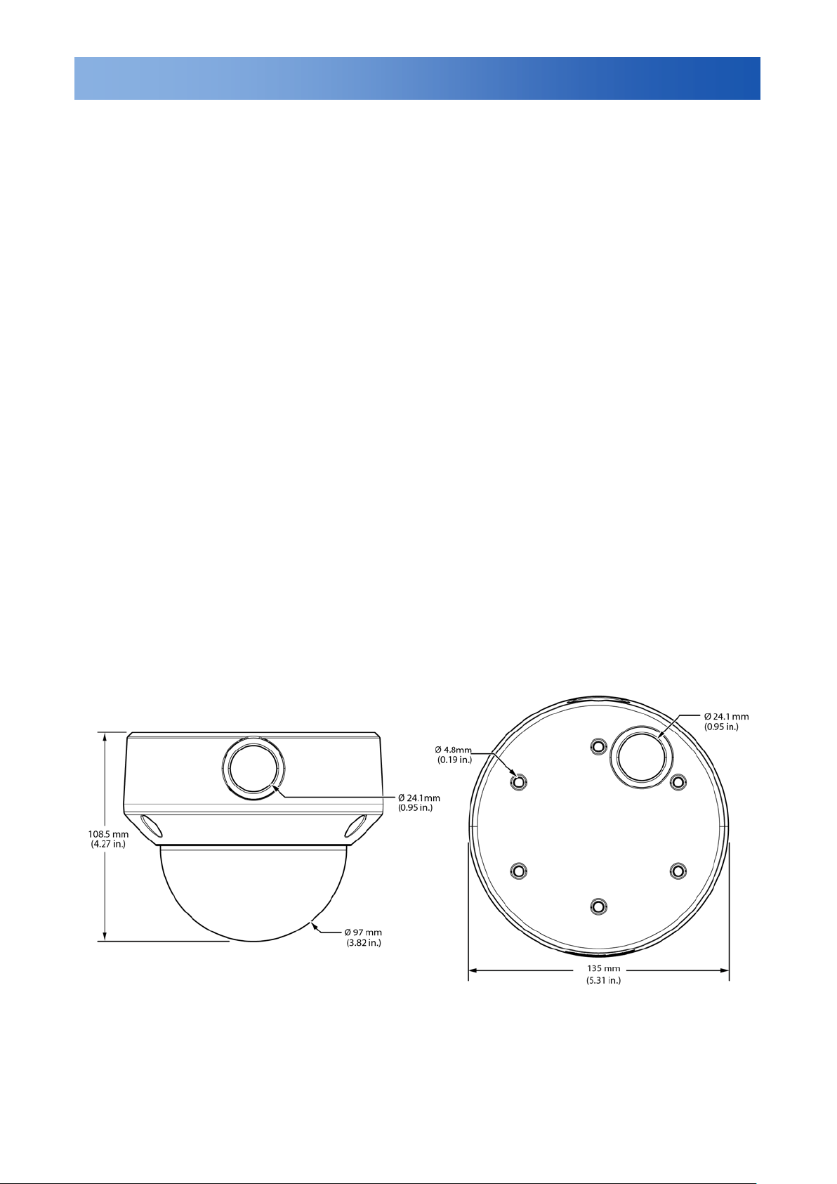
1.4 Dimensions
7
EN_C3970M (05/14)
Page 8
Introduction
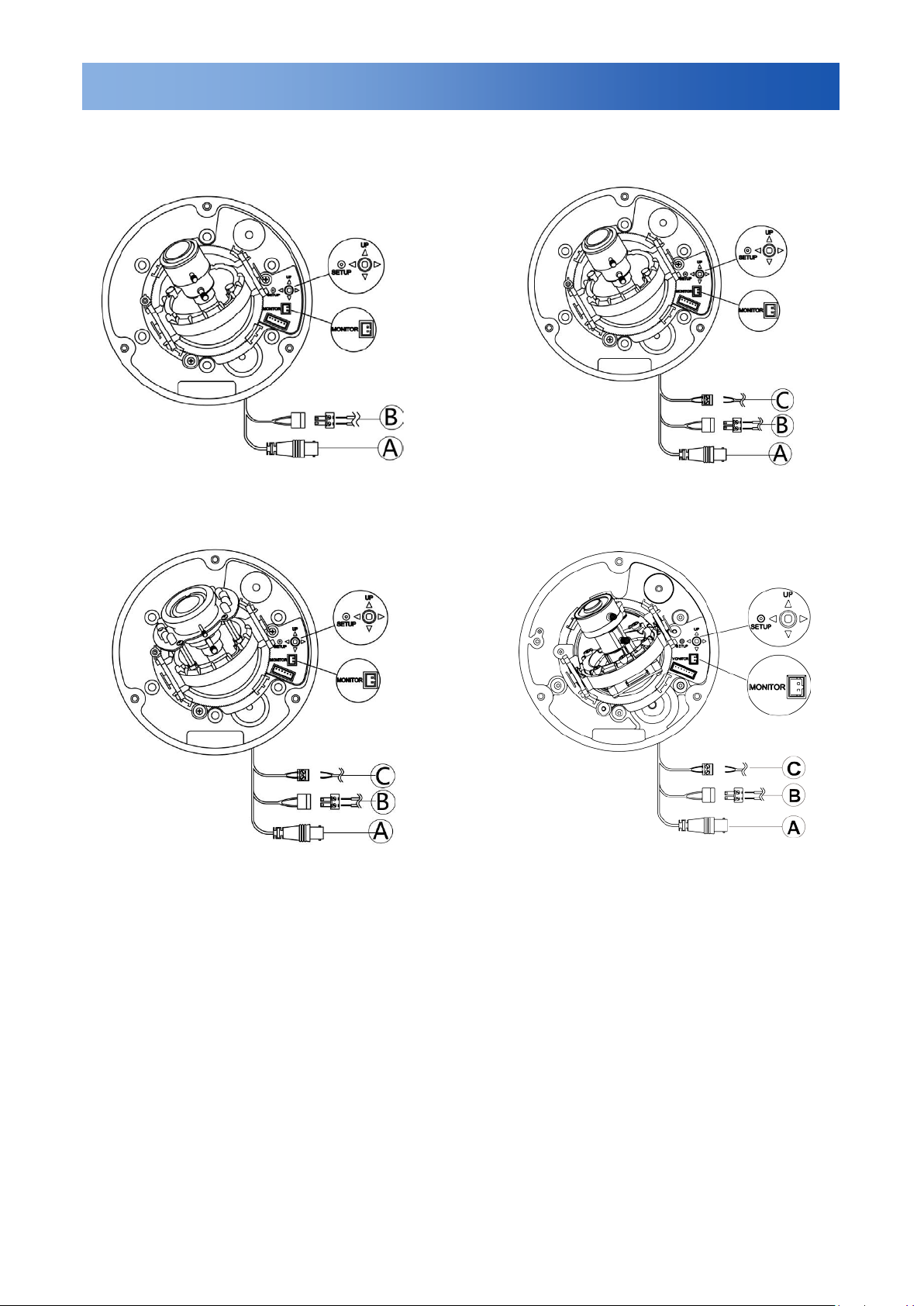
Figure1-2 FD5-DV10-6(X)
Video output conn ect or
Figure1-4 FD5-DWV10-6(X)
FD5-DWV22-6(X)
1.5 Names of Camera Parts
Figure 1-1 FD5-V9-6(X)
Figure1-3 FD5-IRV10-6(X)
A.
B. 18 to 32 VA C /12 VDC power Input connector (Red +/Black -)
C. Alarm Out: Connect to device that responds to alarm signals (Blue+/Brown-).
Note: See Figure 2-7 for camera setup controls.
1.6 Routine Maintenance
• The dome cover is an optical par t . Use a soft, dry cloth to remove any finger prints or dust.
• Clean the camera housing with a soft, dry cloth. For more stubborn stains, use a cloth dampened with
a small quantity of neutral det er gent, then wipe dry.
Caution: Do not use volatile solvents such as alcohol, benzene or thinners to avoid damaging the
surface finish.
8
EN_C3970M (05/14)
Page 9
Installation
1. Bottom case
1. Bottom case
3. Dome cover
FD5-DWV10-6(X)
FD5-DWV22-6(X)
2. Installation
2.1 Disassembling the Camera
Before you mount and adj ust t he camera, follow these steps to disassemble the camera.
1. Loosen the installed t orx screws and remove them.
2. Remove the inner liner by gently pulling it free from the tilt adjustment bracket. For the models without
inner liner, please simply sk ip this step.
3. Set the dome cover (and liner ) asi de.
2. Tilt adjustment bracket
FD5-V9-6(X)/FD5-DV10-6(X)
3. Inner liner
4. Dome cover
FD5-IRV10-6(X)
2. Tilt adjustment bracket
3. Inner liner
4. Dome cover
1. Bottom case
2. Tilt adjustment bracket
9
EN_C3970M (05/14)
Figure 2-1 Disassem ble the Camera
Page 10
Installation
2.2 Installing the Waterproof Plug
Plug the waterproof plug i nto the side conduit hole, or bott om c onduit hole if side conduit hole is used for
wiring. See “2.9 Genera l h elp for installing waterproo f pl ug” f or m or e in formation.
Figure 2-2 Waterproof Plug Installation
2.3 Connecting the Wiring
Refer to Figure 1-1/1-2/1-3/1-4 to connect t he video connect output connector (A) and 24 VAC/18 to 32
VDC power connector (B).
Caution: For DC pow er supply use, make sure the polar ity is correct to avoid malfunct ion and / or
camera damage.
Note: When powering camera using 12VDC, we recommend that the camera is installed with a
separate, isolated power supply to minimize power-r elated video interference.
2.4 Mounting the Camera
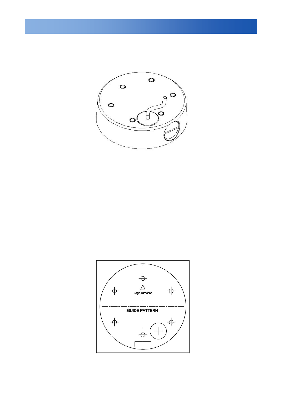
1. Attach the mounting temp late t o t he wall or ceiling.
10
EN_C3970M (05/14)
Figure 2-3
Page 11
Installation
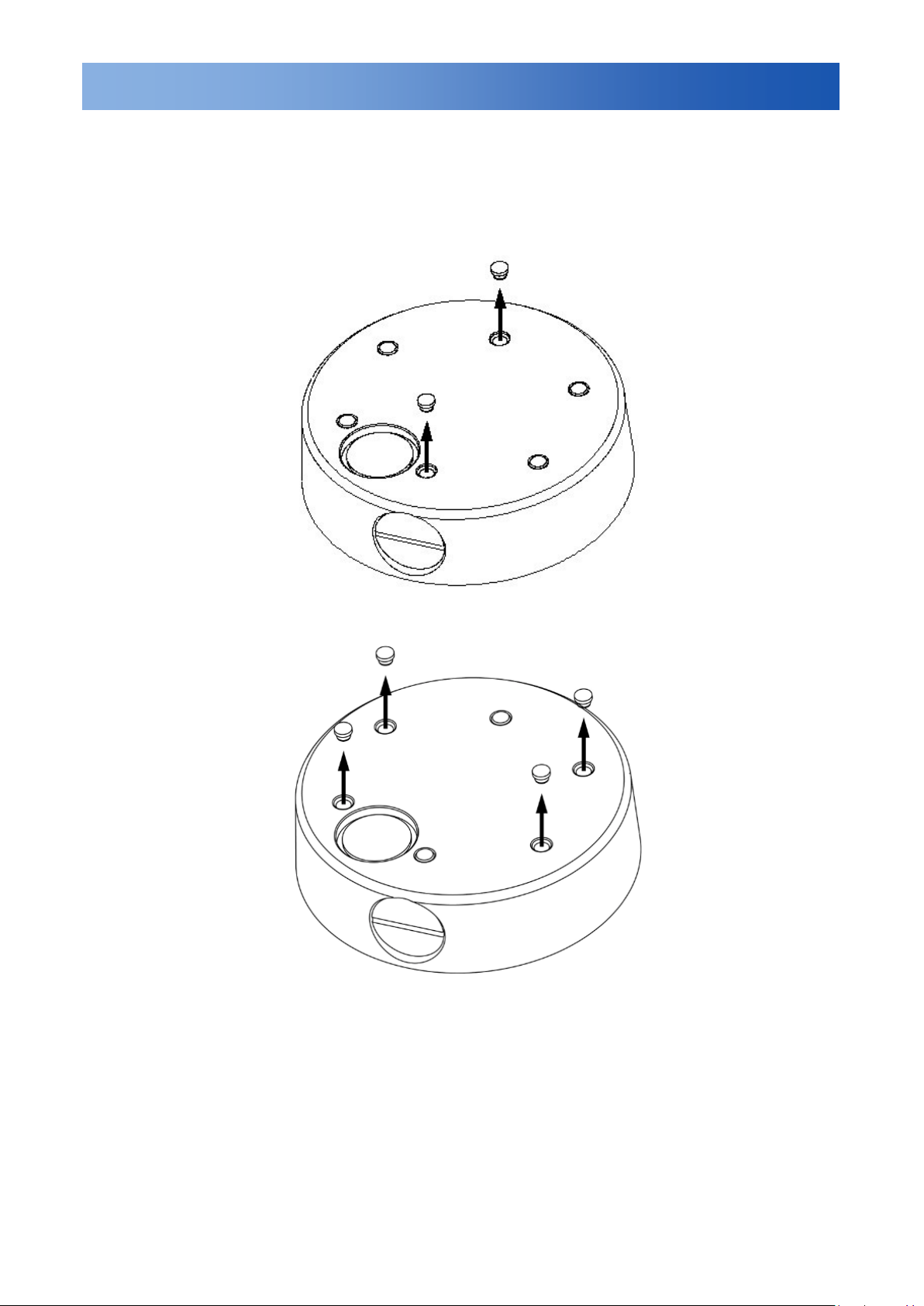
2. Before mounting the dome on a ceiling or a wall, please designate two screw holes or four sc rew
holes and pull out the corresponding outer rubber plugs by us in g t ools like a screwdriver, et c.
Note: With four screw anchors and TP4x25mm tapp ing screws provided, you can cho ose t wo-hole
installation (refer t o Figure 2-4) or change to four-hole installation (ref er t o Figure 2-5) when mounting
the camera on a ceiling or wall. This manual descr ib es two-hole installation only.
Figure 2-4
Figure 2-5
Note: Don’t pull out the other rubber plugs to keep the IP66 performance of the camera. Also, nev er
remove the inside rubber plu gs . Always install mounting scr ew through the inside plug.
11
EN_C3970M (05/14)
Page 12
Installation
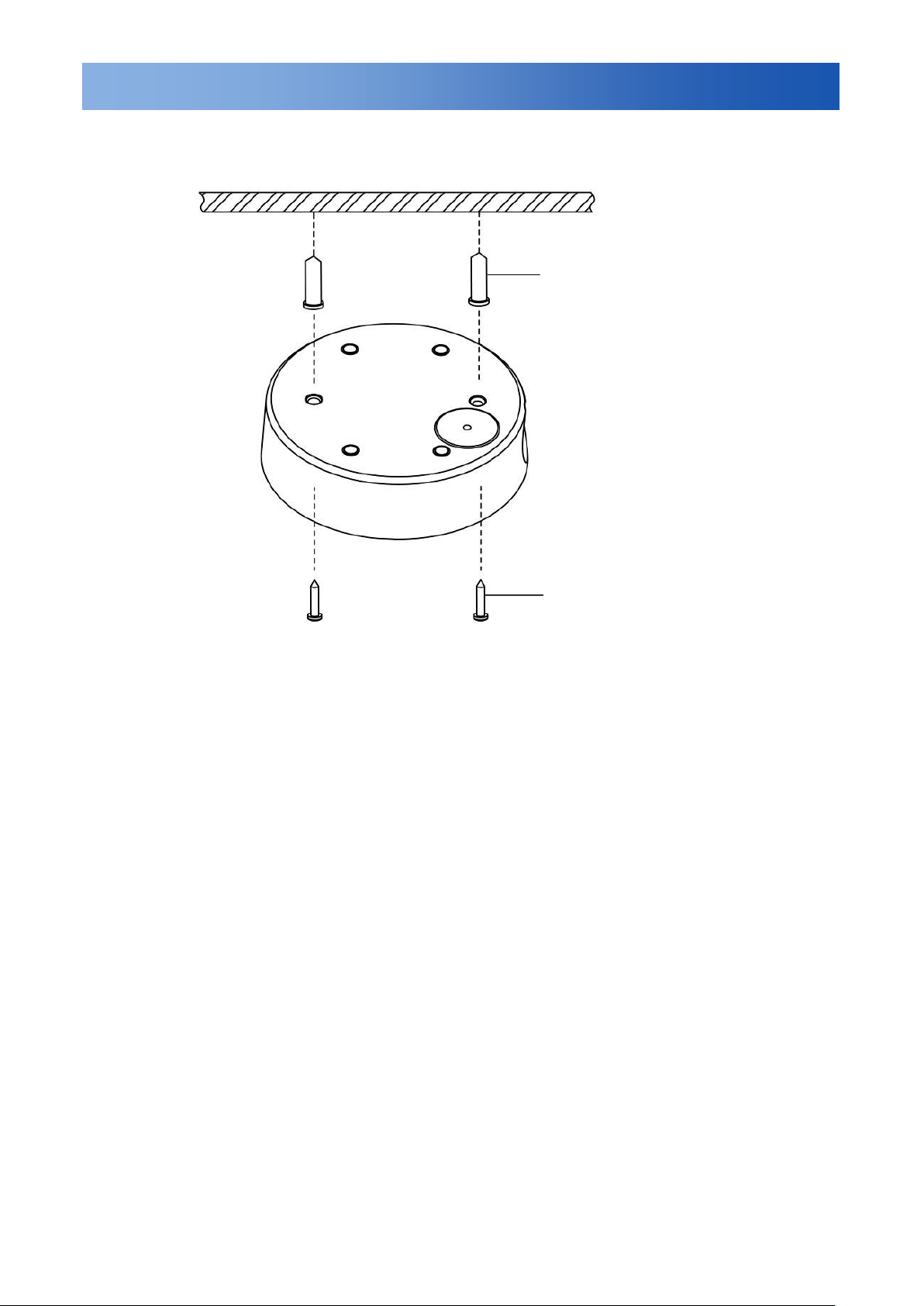
1. Screw anchors (x4), supplied
3. Drill two holes, and then insert the screw anchors (#1) into the holes.
4. Secure the bottom case to the wall or ceiling with the TP4 x 25 mm tapping screws suppl ied (#2).
①
2. TP4 x 25mm tapping screws
(x4), supplied
②
Figure 2-6 (ty pi cal )
Note: Depending on the material of your mounting surface, you may require different screw s and
anchors than those supplied. Use caution to maintain a water t ight seal to the mounting hardware.
12
EN_C3970M (05/14)
Page 13
Installation
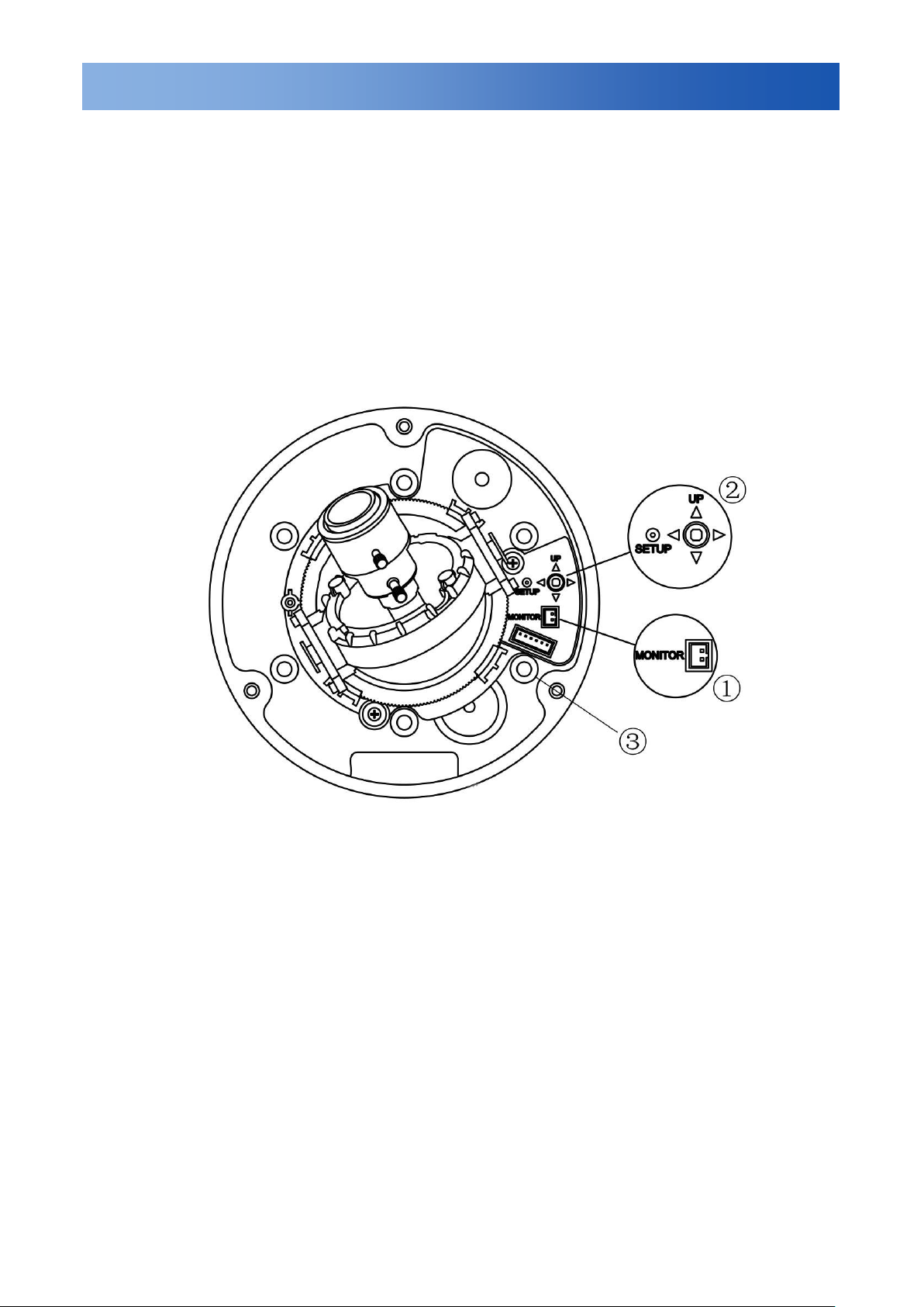
Figure 2-7 Camera Adjustment Controls
2.5 Optional Camera Setti ngs
Refer to Figure 2-7 to loca t e t he OSD joystick control on the camera board. Use the joystick to access
the OSD menu and configur e t he camera settings as required.
To use the OSD joystick control:
• Press the OSD joystick cont rol st r aight down to enter the Main menu or a selected item.
• Move the OSD joystick cont r ol UP, DOWN, LEFT and RIGHT to nav igat e t hrough menus and options.
For further information on OSD settings, refer to the “4.OSD Settings” section.
Note: Connect a local viewing monitor via the optional FD-SC service cable for setup.
1. Monitor out
2. OSD Joystick Control
3. Camera mounting holes
13
EN_C3970M (05/14)
Page 14
Installation
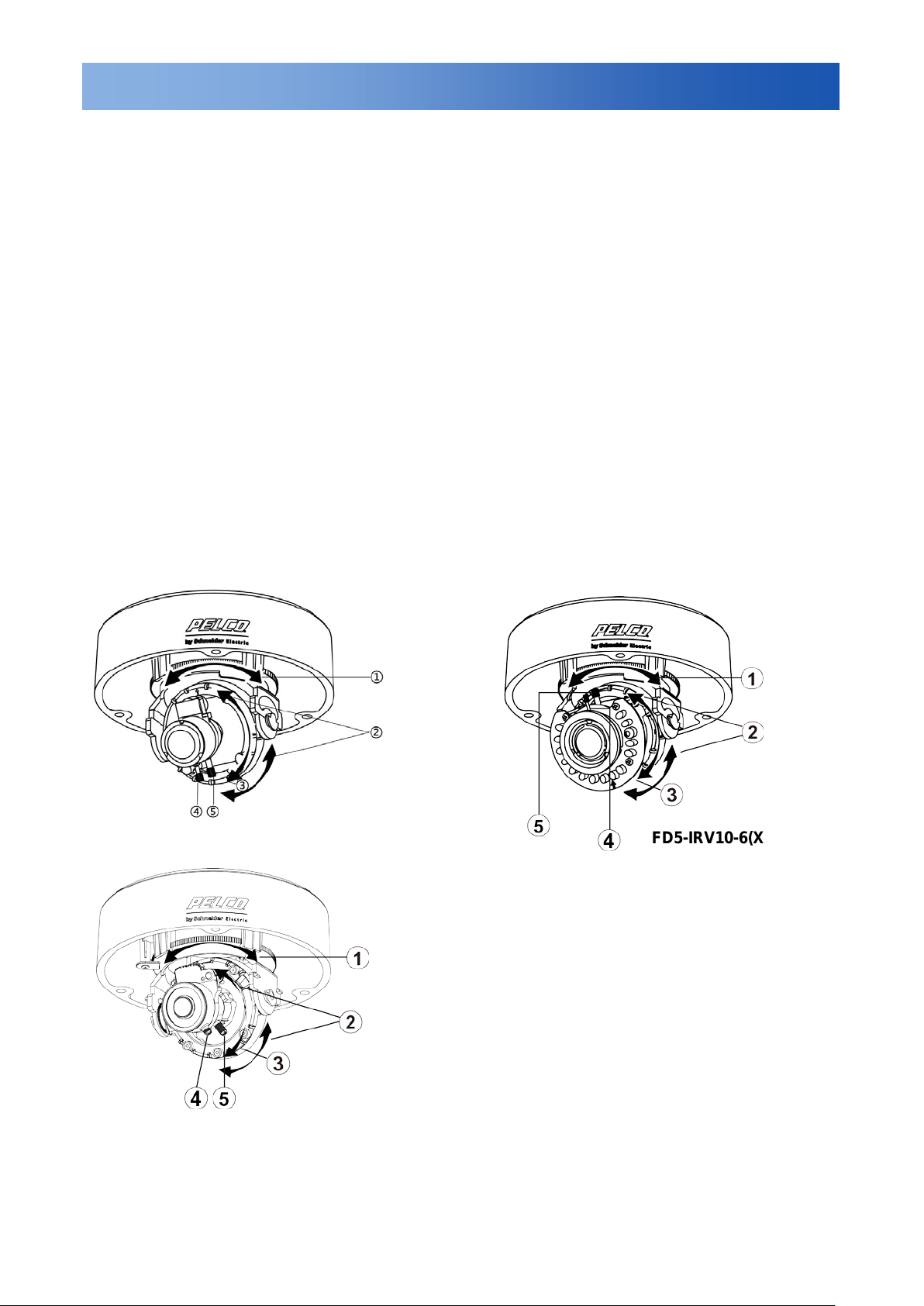
FD5-V9-6(X)/FD5-DV10-6(X)
FD5-IRV10-6(X)
2.6 Adjusting the Camera Position
The dome camera has three axes for positioning the camera. While monit or in g the picture on the monitor,
adjust the camera positio n as follows:
• Pan Adjustment: Rotate 3D asse m bly in the base. Do not turn asse mb ly m or e than 360° as this may
cause the internal cables to t w ist and di s connect or break.
• Tilt Adjustment: After loosening the screw on the br acket, position the camera as desired, and then
tighten the screw back to the bracket.
• Horizontal Rot at ion: For wall mount and t i lt ed ceilings, rotate the lens base ( ma xi m um 360°) until you
are satisfied with the field of v iew.
2.7 Adjusting the Lens (if equipped with vari-focal lens)
1. Loosen the zoom lever (#4) counter-clockwise a littl e, and then rotate the zoom lever and
determine the image view.
2. Loosen the focus lever (#5) counter-clockwise a little, and t hen adjust the focus for optimum
picture sharpness.
3. Re-tighten the zoom lever and focus lever after adjustment.
Note: It is important that you lock the zoom and focus lev er s after making adjustments. Thi s w il l av oid
the positions moving (for example, from temperature changes or vibrations).
Instructions for the Figure 2-8 Camera adjustment:
1. Rotate 3D assembly in base for horizontal adjustme nt
2. Tilt adjustment brac ket and screw for vertical
adjustment
3. Axis ring for horizontal rotation on wall mount / tilted ceilings
4. Zoom lever
5. Focus lever
Figure 2-8 Camera Adjustment
FD5-DWV10-6(X)
FD5-DWV22-6(X)
14
EN_C3970M (05/14)
Page 15

Installation
FD5-DWV10-6(X)
FD5-DWV22-6(X)
1. Bottom case
1. Bottom case
FD5-IRV10-6(X)
1. Bottom case
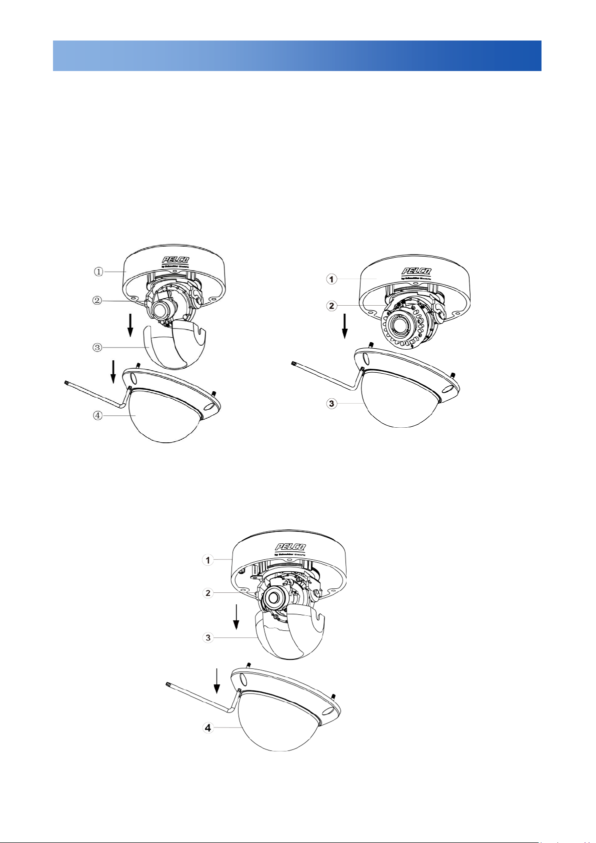
2.8 Completing the Installation
Once all adjustments are done, at t ach and secure the camera housing:
1. Use a soft, lint-free cloth to wipe the dome cover clean and remove fingerprints.
2. Attach the inner liner to t he tilt adjustment bracket. Push down until it clicks into place (w ith no liner
skip this step). Disconnect the optional FD-SC serv ic e c able.
3. Assemble the dome co ver and the bottom case.
2. Tilt adjustment bracket
3. Inner liner
FD5-V9-6(X)/FD5-DV10-6(X)
4. Dome cover
2. Tilt adjustment bracket
3. Inner liner
4. Dome cover
2. Tilt adjustment bracket
3. Dome cover
15
EN_C3970M (05/14)
Figure 2-9 Completing the Installation
Page 16

Installation
2.9 General Help for Waterproof Plug Installation
As “2.2 Installing the waterproof plug” mentioned, install the waterproof plug into the side conduit
hole.
If you want to instal l the waterproof plug to the bottom of the camera, please take the following
steps:
1. Unplug the camera’s internal Output cable connector that inserted in the interface (refer to Figure
2-10) and push the waterp r oof rubber plug out from within camera as shown in Figure 2-11.
Figure 2-10
Figure 2-11
2. Remove waterproof plug from the side of the camera and install it to the bottom as shown in
Figure 2-12.
3. Put Output cable through the side conduit hole and insert the cable waterproof rubber plug into the
side conduit hole (refer to Figure 2-12).
16
EN_C3970M (05/14)
Page 17

Installation
Figure 2-12
Notes:
• Please make sure to lock the b ot t om w aterproof plug to avoid waterpr oof failure.
• Please make sure to plug the cable waterproof rubber plug into the side conduit hole tightly to
avoid waterproof failure.
4. Confirm the internal waterproof rubber plug is tightly fixe d with under cover for preventing i t from
falling out or waterproof fa ilur e ( r efer t o Figure 2-13).
5. Re-plug the camera’s internal output cable connect or.
6. Complete waterproof plug installation.
17
EN_C3970M (05/14)
Figure 2-13
Page 18

OSD Setup Menu
3. OSD Menu
Set up menu
Lens
AUTO AUTO/Manual
Shutter/AGC
WHITE BAL
Backlight
Pic Adjust
ATR
OFF OFF/ON (Luminance, Contrast)
Motion Det
Privacy
Day/Night
NR
OFF
Camera ID
SYNC
Language
Camera Reset
Exit
Save All
INT INT
Default set Menu
AUTO
ATW ATW/Push Lock/User1/User2/Anti CR/Manual
OFF OFF/BLC/HLC
Option Mirror, Brightness, Contrast, Sharpness, Hue, Gain
OFF OFF/ON (Detect Sense, Block DISP, Motion Area, Area Sel)
OFF OFF/ON (Area Sel, Color, Transp, Mosaic)
AUTO AUTO/BW/Color
OFF OFF/ON
English
AUTO (High Luminance, Low Luminance)/ Manual (Mode,
Shutter, AGC)
NR Mode (Off, Y, C)
Y Level
C Level
ENGLISH / SPANISH / RUSSIAN / GERMAN / FRENCH /
JAPANESE or P ORTUGUESE
Table 3-1 OSD Menu of FD5-V9-6(X)/ FD5-DV10-6(X)/ FD5-IRV10-6(X)
The FD5-IRV series camera will automatically switch to B/W mode when the illumination is under a
Note:
certain threshold. Day/Night setting is not available for this model.
18
EN_C3970M (05/14)
Page 19

OSD Setup Menu
ATW, PUSH, USER1, USER2, Anti CR , MANUAL,
PUSH LOCK
Flip, Contrast, Sharpness, Chroma, Blemish Det,
Negative
OFF / ON (Detect Sense, Area Sel, Mode, Top, Bottom,
Left, Right)
OFF / ON (Area Sel, Mode, Position, Color, Transp,
Mosaic)
ENGLISH / SPANISH / RUSSIAN / GERMAN /
FRENCH / JAPANESE or PORTUGUESE
Set up menu
Lens
Default set Menu
AUTO Auto / Manual
Shutter / AGC
White / Bal
HLC / BLC
Pic Adjust
WDR
Motion Det
Privacy
Day / Night
NR
Camera ID
SYNC
Language
Camera Reset
Ezoom
DIS
Full WDR OFF / Full WDR / Light WDR (Contrast)
Option
Option Level
INT INT
Option Auto (High Luminance, Low Luminance)
ATW
Option OFF / BLC / HLC
Option
OFF
AUTO Auto / Color / Mono
OFF OFF / ON
English
Option
Option Mag / Pan / Ti lt
OFF OFF/ON
Focus ADJ
Alarm
Back
Exit
Save All
Option Focus Val
Option Defocus Txt , Alarm Out, Trigger, Normal Out
Table 3-2 OSD Menu of FD5-DWV10-6(X) / FD5-DWV22-6(X)
19
EN_C3970M (05/14)
Page 20

Menu Settings
4. OSD Menu Settings
Entering OSD Menu
Push in on the joystick to open the Main menu. Use the UP/DOWN functions of the joystic k to move the
cursor to the item you want to mod ify . A selected menu item will be highli ghted.
Press UP: Press to move t he c ur sor up.
Press Down: Press to move the cursor down.
Enter button: Push in on the joystick to enter the selecte d item or change the settings of the
selected item.
Press Right: Press to change the settings of the selected item.
Press Left: Press to change the settings of the sele ct ed it em.
Note: When an item is select ed, it w il l be h ighlighted.
After all the settings have been satisfied, move the cursor to the "Save All" item and press the enter
button. Then move the cursor to the "EXIT" item and press t he ent er but t on to exit OSD setup menu.
You can also restore the settings to factory default by moving the cursor to the "CAMERA RESET" item
and then pressing the Enter button. Then move the cursor to the "Save All" item and press the Enter
button.
20
EN_C3970M (05/14)
Page 21

Menu Settings
Section 4 (A) is for models:
FD5-V9-6(X)
FD5-DV10-6(X)
FD5-IRV10-6(X)
Use the OSD menu to set up the camera for optimum performance.
LENS AUTO
SHUTTER/AGC AUTO
WHITE BAL ATW
BACKLIGHT OFF
PICT ADJUST
ATR OFF
MOTION DET OFF
NEXT
EXIT SAVE ALL
PRIVACY OFF
DAY/ N I GHT AU TO
NR
CAMERA ID OFF
SYNC INT
LANGUAGE ENGLISH
CAMERA RESET
BACK
EXIT SAVE ALL
4.1(A) LENS
Select Auto or Manual len s function. The default setting is AUTO (Auto Iris lens). M ove the joystick
control LEFT or RIGHT to select Auto or Manual Lens. Enter t he AUTO submenu as shown in the fi gur e.
Move the joystick control UP or DOWN to open, close, or set I RIS t o aut o m ode. Move the joystick
control UP or DOWN to adjust the DC Iris Lens convergence speed.
If the speed value is lower, t he IRIS will be slower. If speed value is hig her , the IRIS will be faster.
TYPE DC
MODE OPEN
SPEED 046
RETURN
4.2(A) SHUTTER/AGC
Set Shutter speed/AG C (Aut o G ain Control) function. The de fa ult s et t ing is AUTO. Move the joystic k
control LEFT or RIGHT to select AUTO or MANUAL.
SUGGESTED USE:
DC Lens: When using DC lens, we recommend you set SH U TTER/AGC to AUTO mode. Enter the AUTO
submenu as shown in the figure. Move the joystick control UP or DOWN to adjust HIGH LUMINAN CE
MODE to AUTO IRIS.
Manual Lens: When using M ANUAL lens, we recommend you set SHUTTER/AGC to AUTO m ode. Enter
the AUTO submenu as show n in the figure. Move the joystick cont r ol UP or DOWN to adjust HIGH
LUMINANCE MODE and LOW LUMINANCE setting.
21
EN_C3970M (05/14)
Page 22

Menu Settings
RETURN
MODE SHUT+AGC
RETURN
AUTO IRIS and SHUT+AUTO IRIS difference
• Use DC lens and setting to AU TO IRIS mode for normal condition application environments .
The IRIS level will be controll ed by camera brightness.
• Use DC lens and setting to SH U T+ A UTO IRIS mode for high light application environments. The
exposure will be controll ed by AES or the DC Iris. The iris level will be controlled by camera bri ghtness.
HIGH LUMINANCE
MODE AUTO IRIS
BRIGHTNESS 024
LOW LUMINANCE
MODE AGC
BRIGHTNESS x 0.25
This function adjusts the l evel of video out in a low light condition (when AGC mode is ON an d/or SlowShutter mode is ON).
Brightness Level: x0.25, x 0.50, x0.75, x1.00 (default set t ing is x 1. 00 – brightest).
If image is too bright in low-lig ht decr ease the level.
In low light more noise may be seen if Brightness Lev el is set t o x1. 00 with AGC ON mode.
In low light more motion artifacts may be seen if Brightness Level is set to x1.00 with Slow-Shutter ON mode.
This feature is disabled w hen WDR Mode is ON.
The shutter speed is variable from 1/50(1/60) sec to the 1/ 10Ksec and the AGC is selectable depending
on your environment cond ition.
SHUTTER 1/5 0( 1/6 0 )
AGC 6.0
Note:Menu settings for Lens and Shutter/AGC
• When the camera first star t s up t he m enu setting for Lens=Auto (Mode=Auto) and the settings for
Shutter/AGC= High Lu m in ance=Auto Iris
• When you change Lens= M anual then the default settings for Shutter/AGC= High Luminance=Shut
• When you change Lens= Aut o t hen the settings for Shutter/AG C=Shut+AutoIris (this is not t he def ault
value of menu setting when first t ur ned on)
4.3(A) WHITE BAL
WHITE BALANCE contr ol s color on the screen. The default is ATW. The color temperature range is
2500°K ~ 9500°K. Move the joystick control LEFT or RIGHT to select ATW (Auto White Ba lan ce) , PUSH,
PUSH LOCK, USER1, USER2, Anti CR (Anti Color Ro ll ing Suppression) or MANUAL mo de. Ent er t he
ATW submenu as shown i n the figure below. Move the joyst ick control UP or DOWN to select t he
desired value. Select ATW (Auto White Balance) when the scene illu m ination varies between outdoor
scenes and outdoor scen e light ing.
Note: When setting different value of ATW FRAME and application environment, t he color t emperature
range of white balance will be changed. The color temperature r ange of x0.50 of ATW FRAME w il l be
smaller than x2.00.
22
EN_C3970M (05/14)
SPEED 171
DE L AY CNT 152
ATW FRAME x 0.50
ENVIRONMENT OUTDOOR
Page 23

Menu Settings
RETURN
If you select MANUAL mode, you can adjust LEVEL from 17 to 54.
If you select USER1 or USER2 m ode, you can adjust B-GAIN and R-GAIN value fro m 0 to 255.
If you select PUSH mode in the appropriate position, the whole area will perform white balance.
If you select PUSH LOCK mo de i n t he appropriate position, WHITE BALANCE will perform once.
If you select Anti CR mod e in t he appropriate position, the whole area will effectively r est r ain color cast.
4.4(A) BACKLIGHT
Set the Backlight compen sat ion function. The default is OFF. M ove the joystick control LEFT or RIGHT
to select OFF, BLC or HLC (H ighlight Compensation) mo de. When you switched BLC, t he fun c t ion
controls the light level to ov er com e s evere backlighting conditi ons. HLC activated automatically
depending on the shootin g condition (detects night and h igh-luminance)
BLC and HLC Compensat ion are t he functions that achieve the br ightness of a selected area to an
optimum image level. Du e to the intense light coming from the back of objects in the area expected to
view, the auto iris lens tends t o clos e and areas you want to see become dark and invisible.
4.5(A) PICTURE ADJUST
Set the PICTURE ADJUST function. Enter the PICT ADJUST sub me nu as shown in the figure below.
Move the joystick control UP or DOWN to set picture Brightness, Contrast, Sharpness, Hue, or Gain
value. In addition, you can set M IRROR to the ON mode then the picture to be left or right.
MIRROR OFF
BRIGHTNESS 000
CONTRAST 128
SHARPNESS 128
HUE 128
GAIN 128
4.6(A) ATR*
Set the ATR (Adaptive Tone-cur ve Reproduction) functio n. The default is OFF. Move the joys t ick cont r ol
LEFT or RIGHT to select the ON mode, then enter to the ATR submenu. You can set LUMINA CE a nd
CONTRAST to optimize by image.
*Also known as Wide Dynam ic Range. This function expan ds t he video dynamic range of the camera
and improves visibility of ima ges even in high contrast environments.
LUMINANCE LOW
CONTRAST LOW
RETURN
23
EN_C3970M (05/14)
Page 24

Menu Settings
RETURN
R E A S E L 1/8
4.7(A) MOTION DET
Set the Motion Detection function. MOTION DET allows movin g objects to be detected on the screen.
The default is OFF. Move the joy st ick control LEFT or RIGHT to sel ect the ON mode then enter to the
MOTION DET submenu. You can set 4 motion areas t o det ec t mov i ng objectives and adjust t he motion
detection sensitivity. Use the LEFT/RIGHT function s of the j oystick control to set the sensitiv it y from 000
to 127.
DETECT SENSE 100
BLOCK DISP OFF
MONITOR AREA OFF
AREA SEL 1/4
TOP 000
BOTTOM 000
LEFT 000
RIGHT 000
Note: Only FD5-DV10(X) and FD5-IRV10(X) have "Alarm Out”, but no me nu items for this function, so
you can set the alarm out by followi ng these instructions:
For FD5-DV10(X)/ FD5-IRV10(X), the motion detect ion item also controls alarm out. So you need to
select the motion detection function to set alarm out.
Select BLOC K DISP to trigger motion det ection. If something is moving in t he area, the image will show
blocks. It is just a warning me ssage to the user. Ente r but t on ar ound 2~3 sec, It will exit to BLO CK DIS P.
MONITOR A REA also mea n s " Alarm Area". If you use the model included "Alarm Out", you can set t he
area you want to trigger mot ion detection when there is somet hing moving in your selected ar ea. I f you
have connected externa l devices such as sirens or flashing li ght s t o the alarm output connector t o s ig nal
users of the camera that an alar m is act ivated.
4.8(A) PRIVACY
Set the Privacy function. The default setting is OFF. Move the joystick control LEFT or RIGHT to select
the ON mode then enter to t he PRIVACY submenu. You can configure 8 privacy positions, set 8 privacy
areas, choose different color zones and set transparency of 8 privacy zones. However i f y ou enable the
MOTION DET function, then the PRIVACY funct ion wil l support 4 zones only. In addition, the im age of
PRIVACY can allow you t o set the MOSAIC function.
TOP 000
BOTTOM 000
LEFT 000
RIGHT 000
COLOR 1
TRANSP 0.00
MOSAIC OFF
RETURN
24
EN_C3970M (05/14)
Page 25

Menu Settings
RETURN
RETURN
4.9(A) DAY/NIGHT
Set the DAY/NIGHT function. The default setting is AUTO. Mov e t he joystick control LEFT or RIGHT to
select the AUTO, COLOR, BW mode. Enter the AUTO sub menu as shown in the figure below. Move the
joystick control UP or DOWN to adjust BURST value and set t he t ime before the camera switches to
DAY-> NIGHT mode or NIGHT->DAY mode.
Select Day->NIGHT level to set up switchover point of bright ness from COLOR mode to B/W mode
under different Lux levels.
Select NIG HT->DAY level to set up switchover point of brightness from B/W mode to COLOR mode
under different Lux levels.
If you selected COLOR mode, you can force the camera to stay in DAY ( COLOR) mode.
If you selected BW mode, you can force the camera to stay in BW (NIGHT) mode. The BW submen u
allows you to turn ON or OFF the BURST signal. What’s the difference between BURS T O N a nd BURST
OFF? When you select ON, the image is color w ith the signal of Y (BRIGHT) / C (COLOR); however, the
signal value of C (COLOR) is 0.
Note:
The FD5-IRV series camera will automatically switch to B/W mode when the illumination is under a
certain threshold. There is no need to adjust this setting.
BURST OFF
DELAY CNT 100
DAY->NIGHT 100
NIGHT->DAY 100
4.10(A) NR
You can configure the 2D DNR (Digital Noise Reduction) settings and reduce noise on the screen. Enter
NR submenu as shown in t he fi gur e below. Move the joystick cont r ol UP or DOWN to set NR MODE.
When you enable the NR MO DE to the Y (BRIGHT) / C (COLOR), C L E VEL or Y LEVEL mode, you can
adjust Y LEVEL or C LEVEL depending on your environment condition.
Note: When the Y Level value higher the noise in dark areas lessons. Also, the resolution will becom e
lower. When it is lower, there is more noise in dark areas.
When the C Level is highe r t he noise in dark areas lessons. Also, the resolution will become lower.
When it is lower, there is more noise in dark areas.
In the dark environment, you can adjust the value higher o f Y Level to reduce the dark noise; adju s t t he
value higher of C Level to reduce the color noise.
NR MODE Y/C
Y LEVEL 000
C LEVEL 000
25
EN_C3970M (05/14)
Page 26

Menu Settings
4.11(A) CAMERA ID
CAMERA ID displays ON or OFF. The default setting is OFF. You can set the ON mode to add a camer a
title up to 26 characters at 2 lines and on the top of the monitor screen.
4.12(A) SYNC
The default setting is INT. This has no adjustment.
4.13(A) LANGUAGE
OSD supports 6 available languages. The default se tting is English. Move the joy st ick control LEFT or
RIGHT to select the ENGLISH / SPANISH / RUSSIAN / GERMAN / FRENCH / JAPANESE or
PORTUGUESE.
4.14(A) CAMERA RESET
Move to the CAMERA RESE T mode then Press the ENTER key t o r ecal l f actory settings.
4.15(A) SAV E AL L
Save all settings and exit.
Save All” MUST be selected. If not selected, settings will rever t t o pr eviously saved settings if power is
“
cycled.
26
EN_C3970M (05/14)
Page 27

Menu Settings
EXIT SAVE ALL
EXIT SAVE ALL
EXIT SAVE ALL
RETURN
Section 4 (B) is for models:
FD5-DWV10-6(X)/FD5-DWV22-6(X)
Use the OSD menu to set up the camera for optimum performance.
SETUP MENU 1/3
LENS AUTO
SHUTTER/AGC
WHITE BAL ATW
HLC/BLC
PICT ADJUST
WDR FULL WDR
MOTION DET OFF
NEXT
Note: All the value or configurations shown in the figures above are the camera’s default settings.
SETUP MENU 2/3
PRIVACY
DAY/ N I GHT AUTO
NR
CAMERA ID OFF
SYNC INT
LANGUAGE ENGLISH
CAMERA RESET
BACK NEXT
SETUP MENU 3/3
EZOOM
DIS OFF
FOCUS ADJ
ALARM
BACK
4.1(B) LENS
The LENS settings allow y ou to configure Lens and spee d. The options are AUTO (Auto Iris le ns) and
MANUAL. The default setting is AUTO.
In the AUTO submenu, you can set t he M O DE as AUTO. Then select SP EED to adjust the DC Iris Lens
convergence speed from 000~255.
If the speed value is lower, the IRIS will be slower. If the speed value is higher, the IRIS will be faster.
27
EN_C3970M (05/14)
AUTO IRIS
TYPE DC
MODE AUTO
SPEED 048
Page 28

Menu Settings
RETURN
RETURN
4.2(B) SHUTTER/AGC
You can set the SHUTTE R/AGC as AUTO or MANUAL. The d ef ault setting is AUTO.
You can select HIGH LUMINANCE MODE or LOW LUMINA N CE MODE and adjust the BRIGH TN ESS.
The brightness level ranges from 0~255. The IRIS l evel will be controlled by camera br i ght ness.
SUGGESTED USE:
DC Lens: When using the DC lens, we recommend you set SHUTTER/ AGC to AUTO mode. Enter the
AUTO submenu as shown in the figure below. Move t he joystick control UP or DOWN to adjust HIGH
LUMINANCE MODE to AUTO IRIS.
Manual Lens: When using the MANUAL lens, we recommend you set SHUTTER/AG C to AUTO mode.
Enter the AUTO submenu as show n in the figure below. Mov e the joystick control UP or DOWN to adjust
the HIGH LUMINANCE MODE and the LOW LUMINANCE setting.
The shutter speed is variable from 1/50(1/60) sec to the 1/ 10K sec and the AGC is selectable depending
on your environment cond ition.
AUTO IRIS and SHUT+AUTO IRIS difference
• Use the DC lens set to AUTO IRIS mode for nor m al condition application env ironments. The IRIS
level will be controlled by camera brightness.
• Use the DC lens set to SHUT+ A UTO IRIS mode for high light app lication environments. The expo sur e
will be controlled by AES or t he DC Iris. The iris level will be contro ll ed by camera brightness.
In HIGH LUMINANCE MO DE, t he s ubmenu appears as follows. When the high luminance mod e is on,
the shut could not be set.
AUTO SETUP
HIGH LUMINANCE
MODE AUTO IRIS
BRIGHTNESS 034
LOW LUMINANCE
MODE AGC
BRIGHTNESS -
HIGH LUMINANCE SETUP
SHUT -
28
EN_C3970M (05/14)
Page 29

Menu Settings
LOW LUMINANCE SETUP
RETURN
In LOW LUMINANCE MODE, LOW LUMINANCE could be set as AGC, SLOW, AGC→SLOW, AGC→
SLOW→AGC, and OFF.
BRIGHTNESS adjusts the level of video out in low-light conditions (when AGC mode is ON and/or Slow-
Shutter mode is ON). Brig htness Level: x0.25, x0.50, x0. 75, x1.00 (default setting is x1.00 - brightest)
If the image is too bright in low light, decrease the level.
In low light more noise may be seen if the brightness Level is set to x1.00 with AG C ON mode.
In low light more motion ar tifacts may be seen if the Bright ness Level is set to x1.00 with Slow -Shutter
ON mode.
Enter the LOW LUMINANCE MODE subm enu shown as the following figure.
There are 10 levels for selectio n. Depending on your environment condition, SLOW SHUT could be
selected as OFF, x2, x4, x8, x 16, x32, x64, x128, x256; the defau lt SLOW SHUT is x4.
AGC 010
SLOW SHUT x4
Note: Menu settings for Lens and Shutter/AGC
• When the camera first star t s up t he m enu setting for Lens=Auto (Mode=Auto) and the settings for
Shutter/AGC=High Luminance=Auto Iris
• When you change Lens= M anual then the default settings for Shutter/AGC=High Lu m inance=Shut
• Slow Shutter is a method of a longer time passing from the mo me nt the shutter opens till the moment it
closes, by which the came r a lens is able to accumulate enough light intensity under low illuminating
environment for a better image. The bigger the value select ed, the slower the shutter will be adopted.
4.3(B) WHITE BAL
WHITE BALANCE contr ol s color on the screen. Options include ATW (Auto White Balance), PUSH,
USER1, USER2, Anti CR (Ant i Color Rolling Suppressio n) , MANUAL or PUSH LOCK mode. The default
is ATW. The color temperat ur e r ange is 2500°K ~ 9500°K.
Enter the ATW submenu as shown in the figure below. Sele ct ATW when the scene illumination var ies
between indoor scenes a nd outdoor scene lighting. The SP EED and DELAY CNT have 000~255 levels
to select respectively. You can set ATW FRAME as x0.5, 1. 0, 1.5, 2.0 or MAX.
In the Environment submenu, you can choose t he standard, indoor or outdoor accor ding to your
shooting environment.
Note: When you are setting a different value of the AT W FRAME and the appl i c at io n environment, the
color temperature range o f w hite balance will be changed. T he color temperature range of x0.5 of ATW
FRAME will be smaller th an x2. 0.
ATW SETUP
SPEED 016
DE L AY CNT 016
ATW FRAME x1.0
ENVIRONMENT STANDARD
RETURN
29
EN_C3970M (05/14)
Page 30

Menu Settings
RETURN
RETURN
If you selected MANUAL mode as shown in the following figure, you can adjust the LEVEL by pushing
enter or preset the configuration.
MANUAL WB
LEVEL UP PUSH ENTER
LEVEL DOWN PUSH ENTER
PRESET
If you selected USER1 or USE R2 mode as shown in the follow ing fi gures , you can adjust the B-GAIN
and R-GAIN values from 000 to 255.
USER1 WB
B-GAIN 029
R-GAIN 050
RETURN
USER2 WB
B-GAIN 045
R-GAIN 038
RETURN
If you selected PUSH mode in the appropriate position, the whole area will perform white bal ance.
If you selected PUSH LOCK m ode in the appropriate posit ion, WHITE BALANCE will perform
once.
If you selected Anti CR mode i n the appropriate position, the whole area will effectively restr ai n
color cast.
4.4(B) HLC/BLC
Set the Backlight Compensation (BLC) function and the Highlight Co m pensation (HLC) function. B LC
and HLC Compensation a r e t he functions that achieve the br ightness of a selected area to an optimum
image level. Due to the intense lig ht c oming from the back of objects in the area expected to view, the
auto iris lens tends to close and areas you want to see beco me dark and invisible.
Available options inclu de OFF, ON or AUTO mode. The d ef ault is OFF.
If HLC is selected, HLC is act iv ated automatically when the c amera detects high-luminance.
When you select ON, the func t i on controls the light level to overcome severe backlighting co nditions.
The clip level ranges from 000 t o 255 and the scale has 15 levels.
HLC/BLC
HLC OFF
CLIP LEVEL 000
SCALE 010
BLC -
30
EN_C3970M (05/14)
Page 31

Menu Settings
4.5(B) PICTURE ADJUST
PICTURE ADJUST allows you to adjust picture settings for the optimal image. In the PICT ADJUST
submenu, you can adjust pictur e Flip, Contrast, Sharpness, Chroma, Blemish detection, or Negative.
The options OFF, V-FLIP, H-FLIP and HV-FLIP are selectable in Flip line.
In the BLEMISH DET subme nu, you can set the blemish compe nsation function. Press <SET> and wait
to be confirmed. After that , t he w hit e ble m ish w i ll be removed, then back to the optimal image.
Contrast could be selected from 000 to 063, Sharpness is 0 00~ 015, and Chroma is 000~008.
PICT ADJUST
FLIP OFF
CONTRAST 038
SHARPNESS 008
CHROMA 002
BLEMISH DET SET
NEGATIVE OFF
RETURN
4.6(B) WDR
Set the WDR (Wide Dynam ic R ange) function. The Wide Dyna m ic Range (WDR) function is intended to
provide clear images even under back light circumst ances where the intensity of illumination can vary
widely.
The default setting is FUL L WDR; it also has the options of OFF and LIGHT WDR. In WDR SETUP
submenu, you can set CONT R AS T as M ID, MIDHIGH, HIGH, LOW or MIDLOW to optimize the image.
The submenu of Light WDR is the same as the WDR SE TUP submenu. Or you can select OFF to close
the WDR function.
WDR SETUP
CONTRAST MID
RETURN
31
EN_C3970M (05/14)
Page 32

Menu Settings
MONITOR AREA
RETURN
DAY/NIGHT SETUP
RETURN
4.7(B) MOTIO N DET
MOTION DET allows you t o det ec t mov i ng objects on the screen. The defa ult i s O FF. I f you select ON,
you will enter the MOTION DET s ubmenu. You can set 4 motion ar eas to detect moving ob jectives and
adjust the motion detection sensitivity. The value of sensitiv ity is from 000 to 127.
DETECT SENSE 111
AREA SEL 1/4
MODE ON
TOP 002
BOTTOM 003
LEFT 004
RIGHT 005
4.8(B) PRIVACY
The PRIVACY function masks up to 15 privacy area s on t he scr een from video monitorin g. The default
setting is OFF. If you select ON, you will enter the P RIVACY submenu. You can configure up to 15
privacy areas and set color and transparency of the pr iv ac y zones. In addition, you can enable MOSAIC
function for the privacy zone.
Note: When TRANSP is 1.00, Mosaic function is not availab le.
4.9(B) DAY/NIGHT
Set the DAY/NIGHT function. The default setting is AUTO. Mov e t he joystick control LEFT or RIGHT to
select the AUTO, COLOR, or MONO mode. Enter the AUTO submenu as shown in the figure below.
Move the joystick control UP or DOWN to turn BURST ON/ O FF and set the time before the camer a
switches to DAY-> NIG HT mode or NIG HT->DAY mode. The Delay C NT has a range from 000 to 255
and both switch modes a ll ow you to select 20 levels.
PRIVACY
AREA SEL 1/1 5
MODE OFF
POSITION COLOR TRANSP -
MOSAIC -
BURST OFF
DE L AY CNT 015
DAY →NIGHT 008
NIGHT→ DAY 012
RETURN
32
EN_C3970M (05/14)
Page 33

Menu Settings
RETURN
Setting threshold for DAY -> NIGHT allows camera to detect and switch mode automatically under userdefined brightness value. The lower the value (Min. 0), the darker the environment needed for the
camera switching from DAY to NIGHT mode.
On the other hand, the threshold of NIGHT -> DAY is for the camera to switch auto mati c ally from NIGHT
to DAY mode under a certain d ef ined value. The higher the v alue (M ax. 20) , t he brighter the environment
needed for auto switching.
If you selected COLOR mode, you can force the camera to st ay in COLOR (DAY) mode.
If you selected MONO mode, you can force the camera to stay in MO NO (NI G HT) mode.
4.10(B) 3D NR
3D NR allows you to configure t he DNR (Digital Noise Reduction) settings to reduce no ise o n the screen.
In the NR submenu, you can ad just NR LEVEL. When you enable t he NR MODE, you can choose LOW,
MIDLOW, MID, MIDHIGH, or HIGH LEVEL depending on y our environment condition.
NR SETUP
LEVEL OFF
RETURN
4.11(B) CAMERA ID
Turn ON to display CAMERA ID or turn OFF to disable. The defa ult set t ing is OFF. You can set to ON
mode to add a camera title up t o 26 characters within 1 line appearing on the top of the monit or s cr een.
4.12(B) SYNC
The default setting is INT. This h as no adjustment.
4.13(B) LANGUAGE
OSD supports 6 multi built-in languages. The default set t ing is English. Options include E NG LI SH /
SPANISH / RUSSIAN / GERMAN / FRENCH / JAPANESE or PORTUGUESE.
4.14(B) CAMERA RESET
Move to the CAMERA RESE T mode then Press the ENTER key t o r ecal l f actory settings.
4.15(B) EZOOM
Enter EZOOM SETUP submenu as shown in the following figure. Move the joystick control LEFT or
RIGHT to select PAN /TILT value for zooming in and out f the image. The PAN range is 000~1023 and
the TILT range is 000~51 10.
EZOOM SETUP
MAG 000
PAN 512
TILT 256
33
EN_C3970M (05/14)
Page 34

Menu Settings
RETURN
4.16(B) DIS
The DIS (Digital Image Stabilizer) function detects a shaking image due to camera shaking, and perform
digital compensation processing to st abilize the image output. Th e default setting is OFF.
• Note: When you choose DIS on, EZOOM function is NOT configurable at the same time.
4.17(B) FOCUS ADJ
The value shown is for reference on the precision of the focus level. The larger the value, the clearer the
image will be.
ADJUST FOCUS OF THE LENS
FOCUS VAL 2121
RETURN
4.18(B) ALARM
In this function line, you can set a series of general parameters for ALARM. Press joystick control to
enter the ALARM SETUP submenu as shown in the figure below.
ALARM SETUP
DEFOCUS TXT
ALARM OUT
TRIGGER AUX
NORMAL OUT OPEN
For Submenu DEFOCUS TXT
Choose and press joystick control to enter the D EFOCUS TXT SETUP submenu as shown in the figure
below. The DEFOCUS TXT can be set as Off/ON, DEFOCUS LEVEL is 000~007. Use this feature when
your application requir es screen notification of a ca m er a tamper.
For Submenu ALARM O UT
You can configure the ALARM OUT TRIGGER as AUX or MOTION DET. Choose AUX when your
application requires that the Coaxitron
MOTION DET when your application requires that when motion is detected the Alarm Out is activated.
Only one type of Alarm Out can be specif ied.
DEFOCUS SETUP
DEFOCUS TXT OFF
DEFOCUS LEV 003
RETURN
®
remote control will be used to activate the Alarm Out. Choose
34
EN_C3970M (05/14)
Page 35

Menu Settings
Note:
When set to AUX, the Alarm Out function will operate as follows from Coaxitron
• AUX 1: Activates Alarm Out
• AUX 2: Activates Alarm Out for 2 seconds a nd then returns to deactivat ed state
• AUX 3: Deactivates Alarm Out
For Submenu NO RMAL OUT
The default setting is Relay Open. The option can be set to Relay Closed. Configure this setting to
match your attached a ccessory logic.
®
remote control:
4.19(B) REMOTE
This remote function does not show on the OSD menu. It is built in support for PELCO Coaxitron®. A
single video cable connection is used to transmit a video s ig nal and control the PTZ and lens.
4.20(B) SAVE ALL
Save all settings and exit.
35
EN_C3970M (05/14)
Page 36

Specification
Camera System Type
FD5-V9-6
FD5-V9-6X
Format
NTSC
PAL
Optical System
Imager Size
1/3"
IR Cut Filter
Fixed
Electric
Sync System
Internal
Lens Options
F1.2, 3-9mm, DC AI
Horizontal Resolutio n
650 TVL
Min. Object Distance
0.5m~
f/1.2; 2,850°K; 30 IRE
Mono (17ms) 0.1 Lux
f/1.2 ; 30 IRE
Mono (20 ms) 0.1 Lux
Auto: 1/60~1/10,000
Manual: 1/60~10,000
Auto: 1/50~1/10,000
Manual: 1/50~10,000
WDR
On / Off (selectable, ATR)
Noise Reduction-DNR
2D
Motion Detection
Yes - Four (4) areas, sensitivity selectable
Privacy Zones
Yes-8 sizable windows
Camera Titles
Yes
Connection/Termination
Flying leads (through the back)
Set Up/OSD Input Device
Input Buttons/5 Way Rocker
Multi Language
English, Russian, Ger ma n,
French, Spanish, Japa nese
English, Russian, Ger ma n,
French, Spanish, Portuguese
Service Jack(RCA)
2 pin connector for monitor out
Set Up
OSD
Power supply
Power
18 to 32 VAC 50/60 Hz/12 VDC +10% to -15% (Revision A)
Power Consumption
2.5 W (without heater)
15 W (with heater on)
Environment
-30° C to +50°C under power s upply 18 to 32V AC
Operating humidity
20~95% non-condensing
Mechanism
Construction
Aluminum Diecast
Bubble Diameter
< 101mm
Positioning
Impact Resistance
IK10
Dimension
135mm X 108.5mm
Weight(unit)
730g
5. Specifications
FD5-V Series
Field Of V ie w
Sensitivity
Shutter
fW 3mm Horizontal:(78°±2°)° Vertical:(57°±2°)°
fT 9mm Horizontal:31°°Vertical:23°
∞
Color (17 ms) 0.1 Lux
Color (20 ms) 0.1 Lux
Operating Temperature Range
Mechanism/Adjustment
36
EN_C3970M (05/14)
0° C to +50°C under power supply 12V DC
Manual 3 Axis Gimble
Page 37

Specification
Camera System Type
FD5-DV10-6
FD5-DV10-6X
Format
NTSC
PAL
Optical System
Imager Size
1/3"
IR Cut Filter
Yes - D/N Switch
Low Light Technology
ICR
Electric
Sync System
Internal
Lens Options
F1.2, 2.8~10.5mm DC AI
Horizontal Resolutio n
650 TVL
Min. Object Distance
f/1.2; 2,850°K; 30 IRE
Mono (17ms) 0.05 Lux
f/1.2 ; 30 IRE
Mono (20 ms) 0.05 Lux
Auto: 1/60~1/10,000
Auto: 1/50~1/10,000
WDR
On / Off (selectable, ATR)
Noise Reduction-DNR
2D
Motion Detection
Yes - Four (4) areas, sensitivity selectable
Privacy Zones
Yes-8 sizable windows
Camera Tit les
Yes
Camera ID
Yes
Connection/Termination
Flying leads (through the back)
Set Up/OSD Input Device
Input Buttons/5 Way Rocker
Multi Language
English, Russian, Ger ma n,
French, Spanish, Japa nese
English, Russian, Ger ma n,
French, Spanish, Portuguese
Service Jack(RCA)
2 pin connector for monitor out
Set Up
OSD
Power supply
Power
Power Consumption
2.5 W (without heater)
15 W (with heater on)
Environment
-30° C to +50°C under power s upply 18 to 32 V AC
0° C to +50°C under power supply 12V DC
Operating humidity
20~95% non-condensing
Mechanism
Construction
Aluminum Diecast
Bubble Diameter
< 101mm
Positioning
Mechanism/Adjustment
Impact Resistance
IK10
Dimension
135mm X 108.5mm
Weight(unit)
730g
FD5-DV Series
Field Of V ie w
Sensitivity
Shutter
fW 2.8mm Horizontal:(97°±2°) Vertical:(70°±2°)
fT 10.5mm Horizontal:27°Vertical:20°
Color (17 ms) 0.1 Lux
Manual: 1/60~10,000
18 to 32 VAC 50/60 Hz/12 VDC +10% to -15% (Revision A)
0.3m~∞
Color (20 ms) 0.1 Lux
Manual: 1/50~10,000
Operating Temperature Range
37
EN_C3970M (05/14)
Manual 3 Axis Gimble
Page 38

Specification
Camera System Type
FD5-IRV10-6
FD5-IRV10-6X
Format
NTSC
PAL
Optical System
Imager Size
1/3"
IR Cut Filter
Yes - D/N Switch
Low Light Technology
ICR and LEDs
Electric
Sync System
Internal
Lens Options
F1.2, 2.8~10.5mm DC AI
Horizontal Resolutio n
650 TVL
Min. Object Distance
f/1.2; 2,850°K; 30 IRE
Mono (with IR) 0 Lux
f/1.2; 2,850°K; 30 IRE
Mono (with IR) 0 Lux
Auto: 1/60~1/10,000
Auto: 1/50~1/10,000
IR Illuminatio n Type
IR compensation
IR Illumina tion Distance
25 meters
IR Sensitivity
850nm >40% Peak Response
WDR
On / Off (selectable, ATR)
Noise Reduction-DNR
2D
Motion Detection
Yes - Four (4) areas, sensitivity selectable
Privacy Zones
Yes-8 sizable windows
Camera Tit les
Yes
Camera ID
Yes
Connection/Termination
Flying leads (through the back)
Set Up/OSD Input Device
Input Buttons/5 Way Rocker
Multi Language
English, Russian, Ger ma n,
English, Russian, Ger ma n,
Service Jack(RCA)
2 pin connector for monitor out
Set Up
OSD
Power supply
Power
18 to 32 VAC 50/60 Hz/12 VDC +10% to -15% (Revision A)
Power Consumption
4W (IR on, without heater)
17W (IR on, with heater on)
Environment
-30° C to +50°C under power supply 18 to 32V AC
0° C to +50°C under power supply 12V DC
Operating humidity
20~95% non-condensing
Mechanism
Construction
Aluminum Diecast
Bubble Diameter
< 101mm
Positioning
Mechanism/Adjustment
Impact Resistance
IK10
Dimension
135mm X 108.5mm
Weight(unit)
730g
FD5-IRV Series
Field Of V ie w
Sensitivity
Shutter
fW 2.8mm Horizontal:(97°±2°) Vertical:(70°±2°)
fT 10.5mm Horizontal:27°Vertical:20°
Color (17 ms) 0.1 Lux
Manual: 1/60~10,000
French, Spanish, Japa nese
0.3m~∞
Color (20 ms) 0.1 Lux
Manual: 1/50~10,000
French, Spanish, Portuguese
Operating Temperature Range
38
EN_C3970M (05/14)
Manual 3 Axis Gimble
Page 39

Specification
Camera System Type
FD5-DWV10-6
FD5-DWV10-6X
Format
NTSC
PAL
Optical System
Imager Size
1/3"
IR Cut Filter
Yes - D/N Switch
Low Light Technology
ICR
Electric
Sync System
Internal
Lens Options
F1.2, 2.8-10.5mm, DC AI
Horizontal Resolutio n
650 TVL
Min. Object Distance
f/1.2; 2,850°K; 30IRE
Mono (500 ms) 0.001 Lux
f/1.2; 2,850°K; 30IRE
Mono (500 ms) 0.001 Lux
Auto: 1/60~1/100,000
Slow shutter support: 2X-256X
Auto: 1/50~1/100,000
Slow shutter support: 2X-256X
White Balance
ATW / Push / USER1 / USER2 / ANTI CR / Manual / Push lock
WDR
120dB D-WDR
Noise Reduction-DNR
3D
Motion Detection
Yes - Four (4) areas, sensitivity selectable
Image Stabilization
Yes
Privacy Zones
Yes-15 sizable windows
Camera Titles
Yes
Scene Learning/Analytics
Yes
Remote Access
Coaxitron
Outputs
Yes
Connection/Termination
Flying leads (through the back)
Set Up/OSD Input Device
Input Buttons/5 Way Rocker
Multi Language
English, Russian, Ger ma n,
French, Spanish, Japa nese
English, Russian, Ger ma n,
French, Spanish, Portuguese
Service Jack(RCA)
2 pin connector for monitor out
Set Up
OSD
Power supply
Power
Power Consumption
4W (Heater off)
16W (Heater on )
Environment
-30C ~ +50°C under power s upply 18-32V AC
0° C ~ +50°C under power supply 12V DC
Operating humidity
20~80% non-condensing
Mechanism
Construction
Aluminum Diecast
Bubble Diameter
< 101mm
Positioning
Mechanism/Adjustment
Impact Resistance
IK10
Dimension
135mm X 108.5mm
Weight(unit)
730g
FD5-DWV Series
Field Of V ie w
Sensitivity
Shutter
fW 2.8mm Horizontal:(97°±2°) Vertical:(70°±2°)
fT 10.5mm Horizontal:27°Vertical:20°
Color (17 ms) 0.13 Lux
Color (500 ms) 0.004 Lux
Mono (17 ms) 0.03 Lux
Manual: 1/60~1/10,000
0.3m~∞
Color (20 ms) 0.13 Lux
Color (500 ms) 0.004 Lux
Mono (20 ms) 0.03 Lux
Manual: 1/50~1/10,000
18 to 32 VAC 50/60 Hz/12 VDC +10% to -15% (Revision A)
Operating Temperature Range
39
EN_C3970M (05/14)
Manual 3 Axis Gimble
Page 40

Specification
Camera System Type
FD5-DWV22-6
FD5-DWV22-6X
Format
NTSC
PAL
Optical System
Imager Size
1/3"
IR Cut Filter
Yes - D/N Switch
Low Light Technology
ICR
Electric
Sync System
Internal
Lens Options
F1.5, 9~22mm DC AI
Horizontal Resolutio n
650 TVL
Min. Object Distance
f/1.5; 2,850°K; 30IRE
Mono (500 ms) 0.002 Lux
f/1.5; 2,850°K; 30IRE
Mono (500 ms) 0.002 Lux
Auto: 1/60~1/100,000
Slow shutter support: 2X-256X
Auto: 1/50~1/100,000
Slow shutter support: 2X-256X
White Balance
ATW / Push / USER1 / USER2 / ANTI CR / Manual / Push lock
WDR
120dB D-WDR
Noise Reduction-DNR
3D
Motion Detection
Yes - Four (4) areas, sensitivity selectable
Image Stabilization
Yes
Privacy Zones
Yes-15 sizable windows
Camera Tit les
Yes
Scene Learning/Analytics
Yes
Remote Access
Coaxitron
Outputs
Yes
Connection/Termination
Flying leads (through the back)
Set Up/OSD Input Device
Input Buttons/5 Way Rocker
Multi Language
English, Russian, Ger ma n,
French, Spanish, Japa nese
English, Russian, Ger ma n,
French, Spanish, Portuguese
Service Jack(RCA)
2 pin connector for monitor out
Set Up
OSD
Power supply
Power
Power Consumption
4W (Heater off)
16W (Heater on )
Environment
-30C ~ +50°C under power s upply 18-32V AC
0° C ~ +50°C under power supply 12V DC
Operating humidity
20~80% non-condensing
Mechanism
Construction
Aluminum Diecast
Bubble Diameter
< 101mm
Positioning
Mechanism/Adjustment
Impact Resistance
IK10
Dimension
135mm X 108.5mm
Weight(unit)
730g
FD5-DWV Series
Field Of V ie w
Sensitivity
Shutter
fW 9mm Horizontal:31° Vertical:23°
fT 22mm Horizont al:13°Vertical:10°
Color (17 ms) 0.15 Lux
Color (500 ms) 0.008 Lux
Mono (17 ms) 0.05 Lux
Manual: 1/60~1/10,000
0.3m~∞
Color (20 ms) 0.15 Lux
Color (500 ms) 0.008 Lux
Mono (20 ms) 0.05 Lux
Manual: 1/50~1/10,000
18 to 32 VAC 50/60 Hz/12 VDC +10% to -15% (Revision A)
Operating Temperature Range
40
EN_C3970M (05/14)
Manual 3 Axis Gimble
Page 41

Troubleshooting Information
, Pelco, Inc.
All rights reserved.
Pelco Troubleshooting Contact Information
If the instructions provided fail to solve your problem, contact Pelco Product Support at 1-800-289-9100 (USA and Canada)
or +1-559-292-1981 (international) for assistance. Be sure to have the serial number available when calling.
Do not try to repair the unit yourself. Leave maintenance and repairs to qualified technical personnel only.
Note for Dimension Drawings
NOTE : VALUES IN PARENTHESES ARE INCHES; ALL OTHERS ARE CENTIMETERS.
This equipment contains electrical or electronic co m ponents that must be recycled
properly to comply with Dir ect ive 2002/96/EC of the Europea n Un ion regarding the
disposal of waste electric al and electronic equipment (WEEE). Contact your local
dealer for procedures for recycling this equipment.
REVISION HISTORY
Manual # Date Comments
C3970M 02/14 Revision A
C3970M 04/14 FD5-DWV10 added
C3970M 05/14 FD5-DWV22 added
Pelco, the Pelco logo, a nd other trademarks associated with Pelco pr oducts referred to in this pu blication are trademarks of Pelco, Inc. or its af filiates. © Copyright 2014
ONVIF and the ONVIF logo are t r ademarks of ONVIF Inc. All other product names and services are the prop er t y o f their respective companies.
Product specifications and availability are subject to change without notice.
41
EN_C3970M (05/14)
Page 42

42
Page 43

43
Page 44

44
 Loading...