

Page 1
®
ED25/ED2500/ED2620/ED27
Series Environmental Domes
Installation/Operation Manual
C437M-B (9/95)
PELCO • 3500 Pelco Way • Clovis, CA 93612-5699 • USA • www.pelco.com
(800) 289-9100 or (1-559) 292-1981 • FAX (800) 289-9150 or (1-559) 292-3827
Page 2

TABLE OF CONTENTS
Section Page
1.0 WARNINGS .......................................................................................................................................1
2.0 SCOPE ...............................................................................................................................................2
2.1 DESCRIPTION ......................................................................................................................... 2
3.0 INSTALLATION .................................................................................................................................. 3
3.1 MOUNTING ..............................................................................................................................3
3.2 PAN/TILT INSTALLATION/REMOVAL .................................................................................... 4
3.3 ELECTRICAL WIRING ............................................................................................................. 4
4.0 PAN/TILT LIMIT ADJUSTMENTS ...................................................................................................11
5.0 CARE AND MAINTENANCE ........................................................................................................... 12
6.0 SERVICE AND REPAIR .................................................................................................................. 12
6.1 RECOMMENDED EQUIPMENT AND TOOLS ......................................................................12
6.2 SERVICE TIPS ....................................................................................................................... 12
7.0 EXPLODED ASSEMBLY DIAGRAM ...............................................................................................13
8.0 MECHANICAL PARTS LIST ............................................................................................................ 14
9.0 PAN/TILT ELECTRICAL PARTS LIST ............................................................................................ 14
10.0 MODELS ..........................................................................................................................................15
11.0 SPECIFICATIONS ...........................................................................................................................16
11.1 RECOMMENDED MOUNTS/CONTROLS .............................................................................. 17
12.0 WARRANTY AND RETURN INFORMATION..................................................................................18
LIST OF ILLUSTRATIONS
Figure Page
1 Dimension Drawing ......................................................................................................................... 2
2 FMED25 Installation .......................................................................................................................3
3 PMED25 Installation ....................................................................................................................... 4
4 Power Supply Connection .............................................................................................................. 5
5 ED2520 Series Receiver/Driver Wiring Diagram ............................................................................ 6
6 ED2620/ED2620-SL Wiring Diagram ............................................................................................. 7
7 ED2520/ED2720 Wiring Diagram ...................................................................................................8
8 ED2520-SL/ED2720-SL Wiring Diagram ........................................................................................ 8
9 ED2520-PP/ED2720-PP Wiring Diagram ....................................................................................... 9
10 ED2520SL-PP/ED2720SL-PP Wiring Diagram .............................................................................. 9
11 Video Synch/Alarm Terminal Diagram ......................................................................................... 10
12 Tilt Limit Stop Modification............................................................................................................11
13 Pan Limit Stop Locations ..............................................................................................................11
14 ED25/ED26/ED27 Series Enclosure Exploded Assembly Diagram ............................................. 13
REVISION HISTORY
Manual # Date Comments
C437M-A 10/94 Incorporated addendum covering Section 3.3.3, Video Synchronization,
Alarm Terminal Diagram and Figure 11. Incorporated addendum covering Figure 6, DD2000/DD2000-SL Wiring Diagram.
C437M-B 9/95 Updated Figure 4 and Section 11 to show two (2) 40 Watt heaters per
ECO 95-207. Updated Figure 6 to show correct wiring.
1/96 Figure references in Section 4.0 revised.
Pelco, the Pelco Logo, Camclosure, Esprit, Genex, Legacy, and Spectra are registered trademarks of Pelco. © Copyright 1995, Pelco. All rights reserved.
Endura and ExSite are trademarks of Pelco.
ii PELCO Manual C437M-B (9/95)
Page 3
INSTALLATION/OPERATION MANUAL
ED25/ED2520/ED2620/ED27/ED2720
SERIES ENVIRONMENTAL DOMES
1.0 WARNINGS
Prior to installation and use of this product, the following WARNINGS should be observed.
1. Installation and servicing should only be done by
Qualified Service Personnel and conform to all
Local codes.
2. Unless the unit is specifically marked as a NEMA
Type 3-6P enclosure, it is designed for Indoor use
only and it must not be installed where exposed to
rain and moisture.
3. The product bears the following marks:
CAUTION:
This device is designed to operate at
24 volts AC power.
Input voltage must not exceed 28 volts
or drop below 22 volts or else
DAMAGE TO THE MOTORS
WILL OCCUR.
Should you need technical assistance,
please call (800) 289-9100.
4. Only use replacement parts recommended by
PELCO.
5. After replacement/repair of this unit’s electrical
components, conduct a resistance measurement
between line and exposed parts to verify the exposed
parts have not been connected to line circuitry.
This symbol indicates that dangerous voltage
constituting a risk of electric shock is present
within this unit.
CAUTION:
TO REDUCE THE RISK OF ELECTRICAL
SHOCK, DO NOT REMOVE COVER. NO
USER-SERVICEABLE PARTS INSIDE.
REFER SERVICING TO QUALIFIED
SERVICE PERSONNEL.
This symbol indicates that there are important
operating and maintenance instructions in the
literature accompanying this unit.
CAUTION:
RISK OF ELECTRIC SHOCK.
DO NOT OPEN.
Please thoroughly familiarize yourself with the information in this manual
prior to installation and operation.
PELCO Manual C437M-B (9/95) 1
Page 4
2.0 SCOPE
The information contained in this manual covers the
ED25/ED2520/ED2620/ED27/ED2720 Series Environmental Domes.
2.1 DESCRIPTION
The ED25/ED27 Series can be ordered as a dome only
or with factory installed heater/blower and service light.
Other options include factory assembled integral pan/
tilt and/or Coaxitron/Wiretron receiver/driver.
The ED25 Series is designed for flush mount or pen-
dant mount applications.
The ED25/ED2520/ED2620/ED27/ED2720 Series of
environmental domes have been designed primarily for
outdoor applications, but also can be used indoors. The
14-inch diameter black opaque lower dome has a
smoked viewing window with less than 1 f-stop light
loss. This provides for effective camouflage of the
CCTV security/surveillance system without compromising the quality of the video picture.
The ED2620 Series is a pendant mount dome with in-
tegral pan/tilt and is designed specifically for hard-wire
control applications.
The ED27 Series includes an integral arm and can be
used for wall, parapet, or universal mount applications.
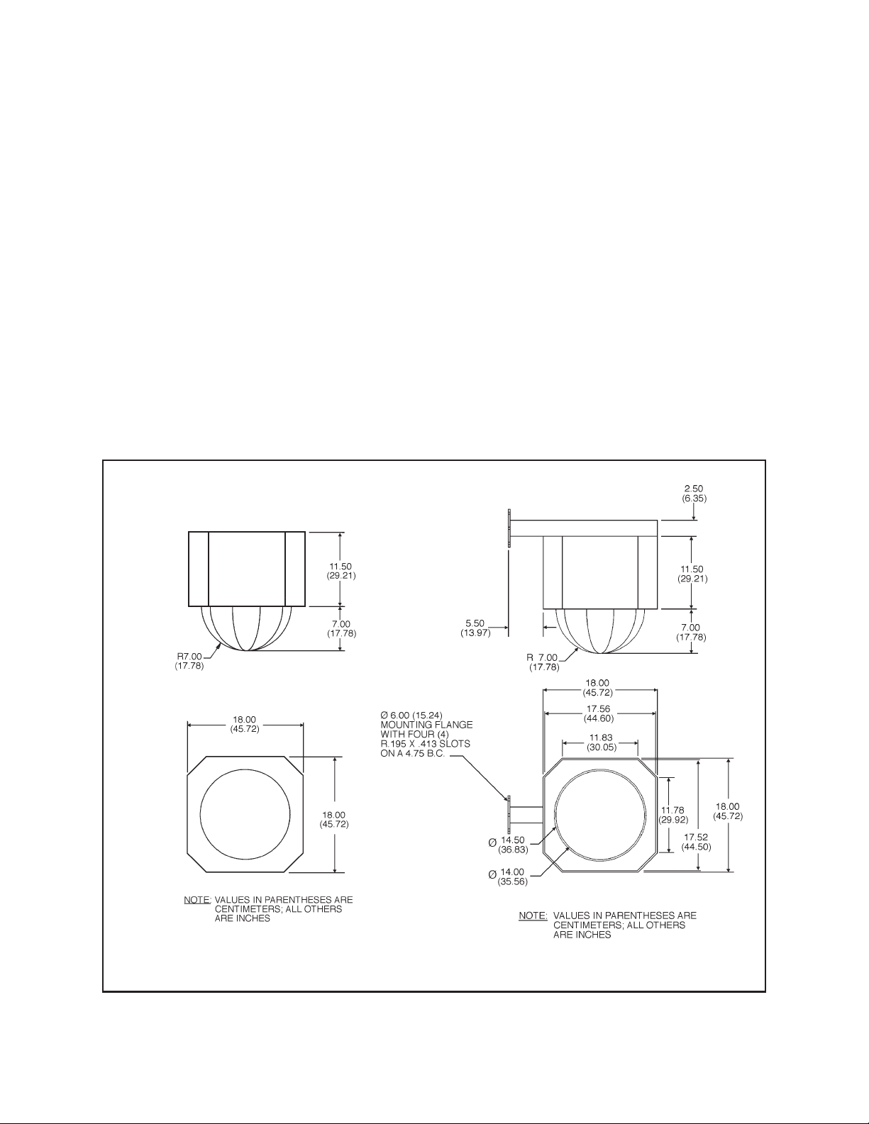
ED25/26 Series ED27 Series
Figure 1. Dimension Drawings
2 PELCO Manual C437M-B (9/95)
Page 5
3.0 INSTALLATION
CAUTION: Make certain that the mounting
surface is capable of supporting the full load of
the mount, pan/tilt, camera/lens and enclosure
• Handle the lower dome with care so as not to
scratch or get fingerprints on the viewing window.
• When installing the unit, loosen the two (2) fasteners and remove the pan/tilt or camera mount to
reduce the total weight of the enclosure.
• When the pan/tilt or camera mount is removed,
install the camera/lens and make sure the electrical connections to the pan/tilt (camera power, lens
power and video) are made.
• When closing the enclosure, be sure the drive tab
on the dome engages the slot on the drive arm of
the pan/tilt.
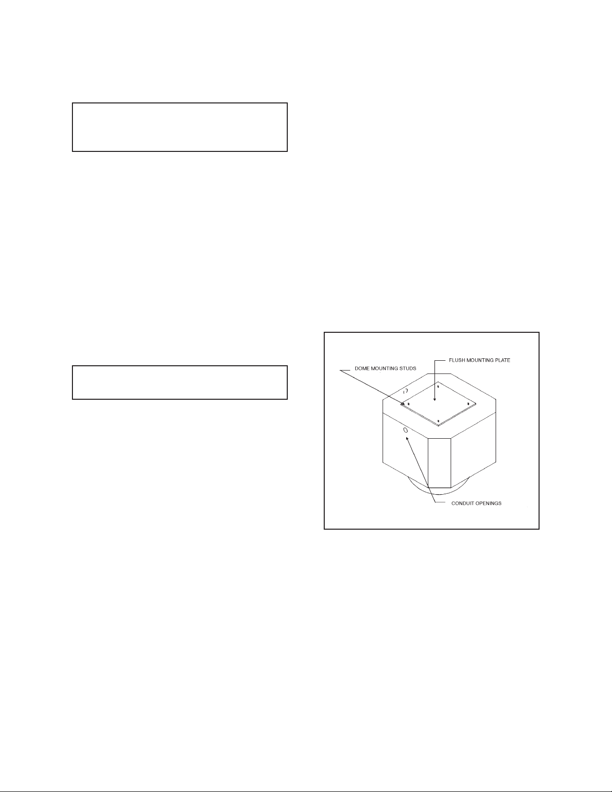
3.1.1 FMED25 Flush Mount Installation
To mount the enclosure using the FMED25 flush mount,
perform the following steps. Refer to Figure 2.
1. Secure the FMED25 flush mounting plate to a suitable surface and secure with suitable fasteners (not
supplied) capable of supporting the weight of the
dome, pan/tilt, camera and lens. Due to the wide
range of installations this mount could be used in,
drilling of holes in the mounting plate will be required.
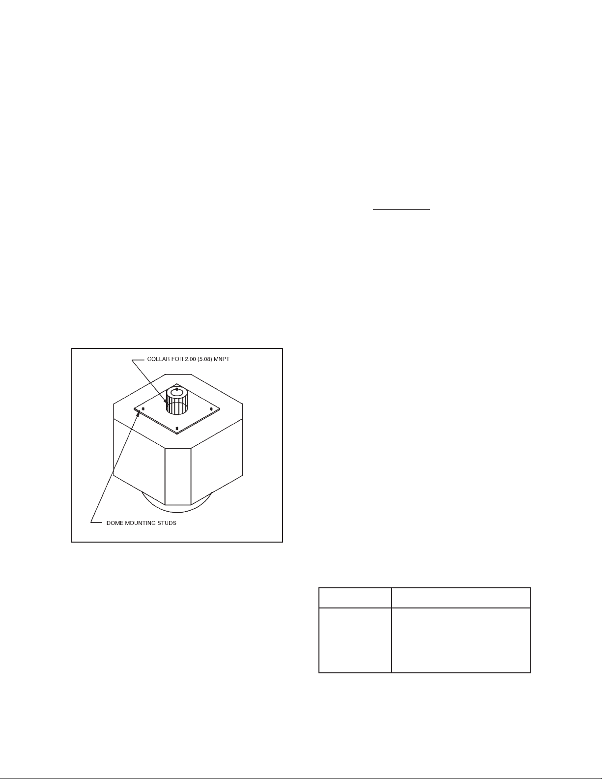
2. Install the provided gasket over the four (4) studs
on the FMED25 mounting plate.
3. Align the four (4) studs in the FMED25 with the
four (4) holes in the top of the dome. Then, secure
the dome to the mounting plate by using the four
(4) 1/4-20 nuts supplied with the mount.
WARNING: Do not rotate pan/tilt by hand.
Rotate by controller only.
3.1 MOUNTING
The ED25/ED2520/ED2620 Series of environmental
domes can be installed by using one of the following
mounts:
• FMED25 Flush mount adapter. Adapts dome
to ceiling. Required for all flush
mount applications.
• PAED25 Discontinued. (Use PA102 with
ED27 Series dome.)
• PMED25 Pendant mount adapter.
• UMED25 Discontinued.
• WMED25 Discontinued. (Use ED27 Series
dome with integral mount.)
Mount the enclosure according the following directions
for the selected mount.
Figure 2. FMED25 Installation
PELCO Manual C437M-B (9/95) 3
Page 6
3.1.2 PMED25 Pendant Mount
Installation
3.2 PAN/TILT INSTALLATION/
REMOVAL
To mount the enclosure using the PMED25 pendant
mount, perform the following steps. Refer to Figure 3.
1. Screw the PMED25 pendant mount to a suitable
length of 1-1/2-inch MNPT threaded pipe which
has been securely fastened to a surface capable of
supporting the weight of the dome, pan/tilt, camera and lens.
(The Pelco MRCA ceiling adapter is recommended
for ceiling mounting applications.)
2. Install the provided gasket over the four (4) studs
on the PMED25 mounting plate.
3. Align the four (4) studs in the PMED25 with the
four (4) holes in the top of the dome. Then, secure
the dome to the mounting plate by using the four
(4) 1/4-20 nuts supplied with the mount.
The following installation instructions are for removing/installing the pan/tilt assembly.
1. The pan/tilt is secured to the back box by two (2)
1/4-20 nuts which hold the pan/tilt mounting
bracket to the integral studs on top of the back box.
2. To remove the pan/tilt, first position the pan/tilt by
using the controller only so it is perpendicular with
the mounting nuts. Then, use a 7/16" socket on a
long extension to reach the nuts holding the pan/
tilt.
3. The mounting nuts need not be removed, just loosened. Once the nuts have been loosened, slide the
pan/tilt so the nuts fit through the “key holes”.
4. To install the pan/tilt, reverse the procedure.
3.3 ELECTRICAL WIRING
The following installation instructions describe how to
connect power to the camera, lens and pan/tilt.
1. The supply circuit should be connected to the input circuit board (pins 8, 9 & 10) as shown in Figure 7.
Figure 3. PMED25 Installation
3.1.3 ED27 Wall Mount Installation
The following installation instructions are for mounting the ED27 Series mount with integral wall mount
arm to an appropriate surface.
1. Mount the mounting plate of the ED27 enclosure
on a suitable surface and secure with suitable fasteners (not supplied) capable of supporting the
weight of the dome, pan/tilt, camera and lens.
2. The pan/tilt and video connection to the receiver/
driver are shown in Figure 8.
3. Basic motor wiring detail for the pan/tilt assembly
is shown in Figure 9.
4. The dome drive pinouts for all models are shown
in Figure 10. Select the appropriate model for your
installation.
3.3.1 Replacement Dome, Pan/Tilt
Chart
Pan/Tilt Dome Enclosure
DD2500 ED2520/ED2720
DD2500-PP ED2520-PP/ED2720-PP
DD2500-SL ED2520-SL/ED2720-SL
DD2500LS-PP ED2520SL-PP/ED2720SL-PP
4 PELCO Manual C437M-B (9/95)
Page 7

3.3.2 Conductor Requirements
The ED25/ED2520/ED27 Series environmental domes
can be connected by a “hard-wire” system, Coaxitron
or Wiretron system. The ED2620 Series dome is designed for hard-wire applications only. The distances
for each of these system is as follows:
Hard-wire Systems Coaxitron System Wiretron System
Cable Size Max. Cable Distance Max. Cable Distance Max. Cable Distance
14 Awg 680 ft (207.3 m) — —
16 Awg 425 ft (129.54 m) — —
18 Awg 265 ft (80.77 m) — —
20 Awg 165 ft (50.29 m) — 10 miles (16,093.44 m)
22 Awg — — 5 miles (8,046.72 m)
RG-59U — 750 ft (228.6 m) —
RG-11U — 1,800 ft (548.64 m) —
RG-6U — 1,500 ft (457.2 m) —
Figure 4. Power Supply Connection
PELCO Manual C437M-B (9/95) 5
Page 8
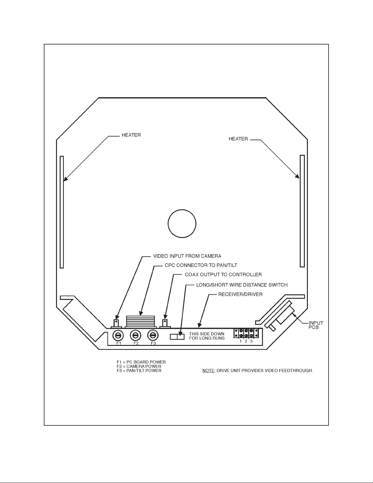
Figure 5. ED2520/ED2720 Series Receiver/Driver Wiring Diagram
6 PELCO Manual C437M-B (9/95)
Page 9

ED2620/ED2620-SL Pan/Tilt Wiring Diagram
Qty Sym Description Part Number
1 C1 Capacitor, 15 MFD 100 V CAPU0015.0/100N
1 C2 Capacitor, 15 MFD 100V CAPU0015.0/100N
1 M1 Pan Motor PT350010010
1 M2 Tilt Motor 2508001
1 J2 Connector CONMAB6100
14 – Connector Pins CON66102-7
4 S1-S4 Switch SWI1SM1
1 – Input Connector CON206305-1
1 – Mating Connector SS1000ASSY
1 – Actuator SWIJS138B
1 – Lens Mating Connector CONMAS6100
1 2
456
12 13 14
Front View
3
9108
7
11
Video Shield 4
Lens Common 13
Safety Ground 8
Common 1
Left 3
Right 7
Down 5
Up 6
Video 2
Camera 9
24 VAC 14
Iris 10
Focus 11
Zoom 12
BRN
RED
BLU
YEL
ORG
W/VIO
W/BLK
WHITE
W/YEL
BLACK
W/BRN
W/RED
W/ORG
GREEN
S1
S2
S3
S4
C1
C2
1
3
2
4
5
M1
M2
J2
Lens
Connector
Input Connector
Figure 6. Wiring Diagram for ED2620/ED2620-SL Dome Drives
PELCO Manual C437M-B (9/95) 7
Page 10
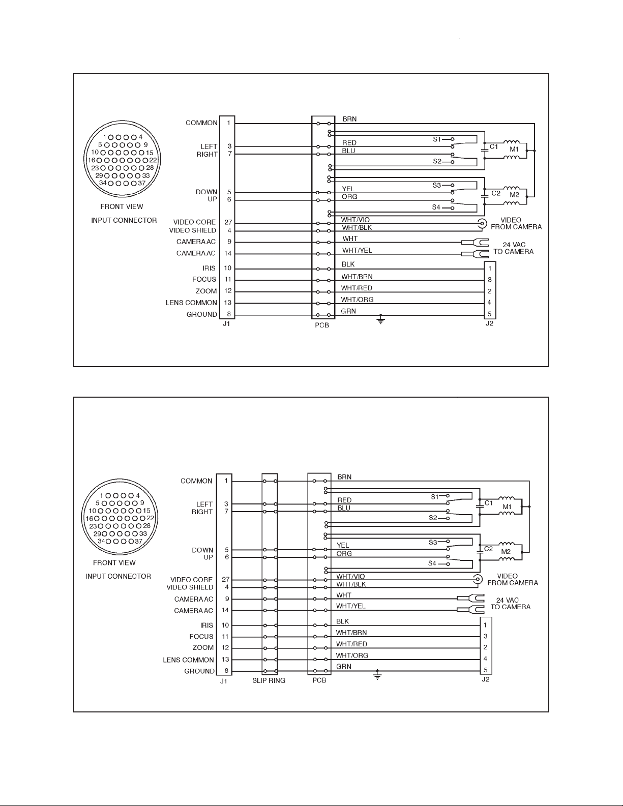
Figure 7. Wiring Diagram for ED2520/ED2720 Dome Drives
Figure 8. Wiring Diagram for ED2520-SL/ED2720-SL Dome Drives
8 PELCO Manual C437M-B (9/95)
Page 11

Figure 9. Wiring Diagram for ED2520-PP/ED2720-PP Dome Drives
Figure 10. Wiring Diagram ED2520SL-PP/ED2720SL-PP Dome Drives
PELCO Manual C437M-B (9/95) 9
Page 12

3.3.3 Video Synchronization, Alarm
Terminal Diagram
The following wiring diagram illustrates the configuration of an additional four-position and six-position
alarm terminal strip and additional video synchronization connection. These terminal strips are factory installed as standard features on ED2520RX-PP,
ED2520SL-RX/PP, ED2720RX-PP and ED2720SLRX/PP models.
Follow the diagram in Figure 11, for appropriate video
synchronization and alarm terminal wiring installation.
Figure 11. Four-position and Six-position Alarm Terminal Strips and Video Synch Connection
10 PELCO Manual C437M-B (9/95)
Page 13

4.0 PAN/TILT LIMIT ADJUSTMENTS
CAUTION: DO NOT attempt to adjust limit
stops when the pan/tilt is in operation. Damage
to the equipment can result. Do not operate
equipment without limit stops.
To adjust limit stops, perform the following steps:
5. Loosen the limit stop actuator (shown in Figure
12). Use the joystick to move the tilt table to the
maximum tilt-up location and then move the limit
stop actuator until it clicks the tilt-up limit switch.
Then lock the limit stop actuator by tightening the
locking screw.
6. Tilt up and down to verify position of the tilt table.
1. Pan to the right using the joystick control until the
desired pan limit is reached. Remove the drive unit
from the back box and adjust the pan limit stop
until it clicks the limit switch. Lock the limit stop
into position and replace pan/tilt. (See Figure 13.)
2. Pan left to the desired stop location and follow the
limit stop adjusting procedure outlined in step #1.
3. Pan left and right to verify that the limit stops have
been positioned properly.
4. The tilt table is designed to move -90° from the
horizontal plane. Note that the tilt adjustment must
never be adjusted beyond the 8 to -90° boundaries.
Note:
• Factory pan limits are set to 0-355° and tilt limits
are set to 0-90° (horizontal to vertical).
• Under normal conditions, the tilt limits should not
have to be reset.
• SL models feature the 360° pan option and are not
supplied with pan limit stops, therefore, only the
tilt limits can be adjusted.
• Pan and tilt spindles are not corrosion protected
and will show signs of corrosion deposit. This is a
normal condition and will not affect the performance of the unit.
Figure 12. Tilt Limit Stop Modification Figure 13. Pan Limit Stop Locations
PELCO Manual C437M-B (9/95) 11
Page 14

5.0 CARE AND MAINTENANCE
6.0 SERVICE AND REPAIR
Regularly scheduled maintenance will prolong the operational life and appearance of the equipment.
IMPORTANT: The lower dome of the ED25
environmental dome is an optical surface. When
cleaning the inner surface of the dome and viewing window, treat as carefully as you would a
fine camera lens.
1. If dust or other debris accumulates on the inside of
the lower dome, remove them with clean air pressure. Compressed air cans are available from photographic equipment dealers.
WARNING: Do not use water, liquid or spray
cleaners of any kind on coated inner surfaces
of the dome.
2. Clean the outer surface of the dome and the inner
surface of the viewing window with a nonabrasive
cleaning cloth and antistatic cleaner that is safe for
use on acrylic plastics. Do not use kerosene or similar substances that can scratch the surface.
6.1 RECOMMENDED EQUIPMENT AND
TOOLS
1. Voltmeter or ohmmeter
2. Allen wrench set
3. Wrench set
4. Screwdriver
5. Pliers, long nose
6.2 SERVICE TIPS
Some common problems encountered with pan/tilt systems include mis-wiring, overloading, and not using
the units for the correct application. Should a failure
occur, it is recommended that the following procedures
be used.
1. If the pan/tilt ceases to operate, turn the control
unit off and remove the supply circuit from the unit.
2. Check the fuse in the control unit using either a
voltmeter or ohmmeter. If open (blown), replace
with the proper recommended fuse.
3. Connect the supply circuit and turn the control on.
If the fuse continues to open (blow), disconnect
the power from the unit.
4. Check the control cable between the control unit
and pan/tilt for shorts, high resistance, or opens.
5. If shorts are not found in the control cable, consult
the factory for further assistance.
12 PELCO Manual C437M-B (9/95)
Page 15

7.0 EXPLODED ASSEMBLY DIAGRAM
Figure 14. ED25/ED26/ED27 Series Enclosure Exploded Assembly Diagram
PELCO Manual C437M-B (9/95) 13
Page 16

8.0 MECHANICAL PARTS LIST
The following parts list corresponds to the exploded assembly diagram in Figure 14.
Item Quantity
1 1 Enclosure front plate assembly ED25001003ASSY
2 1 Lower shock mount ED25004005COMP
3 2 Closing fasteners ED2510000
4, 8 8 Nylon washer SB310005
5 1 Dome ED254004COMP
6 4 Roller insert SB310007
7 4 Dome roller SB34020COMP
4 Roller “O” Ring (not shown) ED210100
9 1 Gas shock EH450010020
10 1 Back box assembly (ED25/ED26 only) ED25001000ASSY
1 Back box for ED27 Series only (not shown) ED241000WA
11 2 Heater Bracket ED25004006COMP
11A 4 Heater Blanket, 120/230 VAC (not shown) EHWD10087
12 1 Lower shock bracket ED25004004COMP
2 Spacer SPA8542
13 Light assembly
1 Lamp holder ED210020
1 Lamp, 120 VAC LAP7C7
Lamp, 230 VAC LAP10S6/10
1 Switch SWIV3L
14 1 Blower EH18013
4 Fan spacer SPA8404
15 1 Terminal input circuit board PCB9000255EASSY
1 Terminal input circuit board, 230 VAC only PCB9000255A
16 1 Mounting plate ED25004011COMP
17 1 Hinge spacer ED25004010COMP
Description
Part Number
9.0 PAN/TILT ELECTRICAL PARTS LIST
Schematic ID
C1–C2 Capacitor, 15 MFD, 100V CAPU0015.0/100N
J1 Input connector CON206044-1
– Mating input connector CONA37S
J2 Lens connector CONMAB6100
Lens connector (SL and PP models) CON206705-1
– Lens mating connector CONMAS6100
Lens mating connector (PP models only) CON206708-1
PCB Interconnecting PCB PCB3000100
Slip Ring Slip Ring (SL models only) 28010000
S1–S4 Limit switches SWI1SM1
M1 Pan motor PT350010010
M2 Tilt motor 2508001
Tilt Pot Preset pot, tilt POTP010.0K
Pan Pot Preset pot, pan POTP010.0K
Preset pot, pan (SL models only) POTDARM010.0K
14 PELCO Manual C437M-B (9/95)
Description
Part Number
Page 17

10.0 MODELS
ED25 14" diameter environmental dome
fixed camera mount. Black opaque
lower dome has smoked viewing window (1 f-stop light loss). (CE)
ED25-1 Same as ED25 except supplied with
service light and heater/blower.
ED2520 14" diameter environmental dome with
black opaque lower dome with smoked
viewing window and integral pan/tilt.
Heater/blower and service light are
standard features. (CE, UL)
ED2520-RX Same as ED2520 except supplied with
Coaxitron receiver/driver.
ED2520-RX-3 Same as ED2520-RX except 230 VAC
input.
ED2520-WX Same as ED2520 except supplied with
Wiretron receiver/driver.
ED2520-SL Same as ED2520 except supplied with
SL option (360° pan setting). (CE)
ED2520SL-RX Same as ED2520-SL except supplied
with Coaxitron receiver/driver. (UL)
ED2520SL-WX Same as ED2520-SL except supplied
with Wiretron receiver/driver.
ED2520-PP Same as ED2520 except supplied with
preset pan/tilt. (CE)
*ED2520RX-PP Same as ED2520-PP except supplied
with Coaxitron receiver/driver.
ED2520SL-PP Same as ED2520-SL except supplied
with preset pan/tilt. (CE)
*ED2520SL-RX/PP Same as ED2520SL-PP except sup-
plied with Coaxitron receiver/driver.
ED2620 14" diameter pendant mount environ-
mental dome with black opaque lower
dome with smoked viewing window
and integral pan/tilt for hard-wired applications. Heaters, blower and light
are standard features. Must be used
with PMED25 pendant mount. (CE)
ED2620-PP Same as ED2620 except supplied with
preset (PP) pan/tilt. (CE)
ED2620-SL Same as ED2620 except supplied with
SL option (360° pan setting). (CE)
ED27 14" diameter environmental dome with
fixed camera mount and integral mount
arm. Black opaque lower dome with 1
f-stop smoked viewing window. (UL)
ED27-1 Same as ED27 except supplied with
service light and factory-installed heater
and blower. (UL)
ED2720 14" diameter environmental dome with
integral mount arm. Dome equipped
with service light, pre-wired integral
pan/tilt and heater/blower. (CE, UL)
ED2720-PP Same as ED2720 except supplied with
preset (PP) pan/tilt. (CE)
ED2720-RX Same as ED2720 except supplied with
Coaxitron receiver/driver.
ED2720-RX-3 Same as ED2720-RX except 230 VAC
input.
*ED2720RX-PP Same as ED2720-RX except supplied
with preset (PP) pan/tilt.
ED2720-WX Same as ED2720 except supplied with
Wiretron receiver/driver.
ED2720-SL Same as ED2720 except supplied with
SL pan/tilt (360° pan rotation). (CE)
ED2720SL-PP Same as ED2720-SL except supplied
with preset (PP) pan/tilt. (CE)
ED2720SL-RX Same as ED2720-SL except supplied
with Coaxitron receiver/driver. (UL)
*ED2720SL-RX/PP Same as ED2720SL-RX except sup-
plied with preset (PP) pan/tilt.
ED2720SL-WX Same as ED2720-SL except supplied
with Wiretron receiver/driver.
* NOTE: Equipped with 4-position and 6position alarm terminal strips and video synchronization connection.
PELCO Manual C437M-B (9/95) 15
Page 18

11.0 SPECIFICATIONS
Enclosure
MECHANICAL
Pan/Tilt
Pan Rotation: 0-355° horizontal
0-360° horizontal (SL models only)
Pan Speed: 24°/sec ±1 degree (no load condition)
Tilt Rotation: -90° movement from horizontal
plane
Tilt Speed: 12° /sec ±.5 degree (no load
condition)
Gearing: Chain and direct drive
Bearings: Pan — Ball bearing and bronze
oilite bushings
Tilt — Bronze oilite bushings
Braking: Friction
ELECTRICAL
Pan/Tilt
Input Voltage: 24 VAC, 50/60 Hz
vA Required for Pan: 7.2 vA
vA Required for Tilt: 9.1 vA
Maximum Current: 2 amps per conductor
(SL models only)
Limit Switches: 5 amp, 250 VAC
Motors: Continuous duty reversing induc-
tion type
Power Cable
Conductor Requirements:
Pan/Tilt 10 conductors
Lens 6 conductors
Camera 2 conductors
Connectors
Pan/Tilt: Pre-wired AMP CPC, 37 pins
Lens:
The following specifications apply to these models:
ED25-1, ED2520, ED2520-SL, ED2520-PP,
ED2520SL-PP, ED2620, ED2620-SL, ED27-1,
ED2720, ED2720-SL, ED2720SL-PP
Input Voltage: 120 VAC, 50/60 Hz
vA Required: 187 vA
Blower: 80 cfm at 13 watts
(continuous operation)
Heaters: Four (4) at40 watts each. Heaters
are thermostatically controlled
to activate ON @ 40°F (4.5°C)
and OFF @ 60°F (15.6°C)
Service Light: 7 watts
Pwr Cable Required: 3 conductor, 18 Awg
(not supplied)
The following specifications apply to these models:
ED2520-RX, ED2520-RX-3, ED2520-WX,
ED2520SL-RX, ED2520SL-WX, ED2520RX-PP,
ED2520SL-RX/PP, ED2720-RX, ED2720-RX-3,
ED2720-WX, ED2720SL-RX, ED2720SL-WX,
ED2720RX-PP, ED2720SL-RX/PP
Input Voltage: 120 VAC or 230 VAC, 50/60 Hz
vA Required: 247 vA
Blower: 80 cfm at 13 watts
(continuous operation)
Heaters : Four (4) at 40 watts each. Heaters
are thermostatically controlled
to activate ON @ 40°F (4.5°C)
and OFF @ 60°F (15.6°C)
Non-PP models: Hirschmann MAB6100, mate
provided
PP models: AMP CPC, 9 socket, mate pro-
vided
Video: Standard BNC
Camera Sync: Standard BNC
Camera Power: Spade lugs
16 PELCO Manual C437M-B (9/95)
Service Light: 7 watts
Pwr Cable Required: 3 conductor, 18 Awg
(not supplied)
Page 19

GENERAL
Enclosure
Max. Camera/Lens
Length: 12.50"L x 4.50"W x 3.25"H
(31.75cm x 11.43cm x 8.25cm)
Construction:
Back Box 0.080" aluminum
Viewing Window Optically clear acrylic which has
been tinted, rated UL94HB.
(Less than 1 f-stop light loss.)
Finish: Semigloss beige,
self-textured baked enamel
Environment: Outdoor
Dimensions: See Figure 1
Ambient Operating
Temperature Range: -10° to 120°F (-23° to 49°C)
Pan/Tilt
Maximum Load: 10 lbs (4.6 kg)
Construction: 0.025" aluminum frame
(Product specifications subject to change without
notice.)
11.1 RECOMMENDED MOUNTS/
CONTROLS
For information on recommended mounts and controls, please contact Pelco for a copy of specification
sheet C437.
WEIGHTS
Back Box Mount Pan/Tilt Rec./Driver Unit
ED25 18 lbs (8.16 kg) 3 lbs (1.36 kg) — — 21 lbs (9.52 kg)
ED25-1 19 lbs (8.61 kg) 3 lbs (1.36 kg) — — 22 lbs (9.97 kg)
ED2520, ED2620 19 lbs (8.61 kg) — 8 lbs (3.63 kg) — 27 lbs (12.25 kg)
ED2520-RX, RX-3 or WX 19 lbs (8.61 kg) — 8 lbs (3.63 kg) 10 lbs (4.54 kg) 37 lbs (16.78 kg)
ED2520-SL, ED2620-SL 19 lbs (8.61 kg) — 9 lbs (4.08 kg) — 28 lbs (12.70 kg)
ED2520-PP, ED2620-PP 19 lbs (8.61 kg) — 9 lbs (4.08 kg) — 28 lbs (12.70 kg)
ED2520SL-PP 19 lbs (8.61 kg) — 9 lbs (4.08 kg) — 28 lbs (12.70 kg)
ED2520SL-RX or -W 19 lbs (8.61 kg) — 9 lbs (4.08 kg) 10 lbs (4.54 kg) 38 lbs (17.24 kg)
ED2520RX-PP 19 lbs (8.61 kg) — 9 lbs (4.08 kg) 11 lbs (4.98 kg) 39 lbs (17.69 kg)
ED2520SL-RX/PP 19 lbs (8.61 kg) — 9 lbs (4.08 kg) 11 lbs (4.98 kg) 39 lbs (17.69 kg)
ED27 23 lbs (10.43 kg) 3 lbs (1.36 kg) — — 26 lbs (11.79 kg)
ED27-1 24 lbs (10.89 kg) 3 lbs (1.36 kg) — — 27 lbs (12.25 kg)
ED2720 24 lbs (10.89 kg) — 10 lbs (4.54 kg) — 34 lbs (15.42 kg)
ED2720-PP 24 lbs (10.89 kg) — 10 lbs (4.54 kg) — 34 lbs (15.42 kg)
ED2720-RX, RX-3, WX 24 lbs (10.89 kg) — 10 lbs (4.54 kg) 11 lbs (4.98 kg) 45 lbs (20.41 kg)
ED2720-SL 24 lbs (10.89 kg) — 10 lbs (4.54 kg) — 34 lbs (15.42 kg)
ED2720SL-PP 24 lbs (10.89 kg) — 10 lbs (4.54 kg) — 34 lbs (15.42 kg)
ED2720SL-RX or WX 24 lbs (10.89 kg) — 10 lbs (4.54 kg) 11 lbs (4.98 kg) 45 lbs (20.41 kg)
ED2720SL-RX/PP 24 lbs (10.89 kg) — 10 lbs (4.54 kg) 11 lbs (4.98 kg) 45 lbs (20.41 kg)
PELCO Manual C437M-B (9/95) 17
Page 20

12.0 WARRANTY AND RETURN
INFORMATION
WARRANTY
Pelco will repair or replace, without charge, any merchandise proved
defective in material or workmanship for a period of one year after the date
of shipment.
Exceptions to this warranty are as noted below:
• Five years on FT/FR8000 Series fiber optic products.
• Three years on Genex
keyboard).
• Three years on Camclosure
CC3701H-2, CC3701H-2X, CC3751H-2, CC3651H-2X, MC3651H-2,
and MC3651H-2X camera models, which have a five-year warranty.
• Two years on standard motorized or fixed focal length lenses.
• Two years on Legacy
DF5/DF8 Series fixed dome products.
• Two years on Spectra®, Esprit®, ExSite™, and PS20 scanners, includ-
ing when used in continuous motion applications.
• Two years on Esprit
wiper blades).
• Eighteen months on DX Series digital video recorders, NVR300
Series network video recorders, and Endura
network-based video products.
• One year (except video heads) on video cassette recorders (VCRs).
Video heads will be covered for a period of six months.
• Six months on all pan and tilts, scanners or preset lenses used in
continuous motion applications (that is, preset scan, tour and auto scan
modes).
Pelco will warrant all replacement parts and repairs for 90 days from the
date of Pelco shipment. All goods requiring warranty repair shall be sent
freight prepaid to Pelco, Clovis, California. Repairs made necessary by
reason of misuse, alteration, normal wear, or accident are not covered
under this warranty.
Pelco assumes no risk and shall be subject to no liability for damages or
loss resulting from the specific use or application made of the Products.
Pelco’s liability for any claim, whether based on breach of contract,
negligence, infringement of any rights of any party or product liability,
relating to the Products shall not exceed the price paid by the Dealer to
Pelco for such Products. In no event will Pelco be liable for any special,
incidental or consequential damages (including loss of use, loss of profit
and claims of third parties) however caused, whether by the negligence
of Pelco or otherwise.
The above warranty provides the Dealer with specific legal rights. The
Dealer may also have additional rights, which are subject to variation from
state to state.
If a warranty repair is required, the Dealer must contact Pelco at (800)
289-9100 or (559) 292-1981 to obtain a Repair Authorization number
(RA), and provide the following information:
1. Model and serial number
2. Date of shipment, P.O. number, Sales Order number, or Pelco invoice
number
3. Details of the defect or problem If there is a dispute regarding the
warranty of a product which does not fall under the warranty conditions
stated above, please include a written explanation with the product
when returned.
Method of return shipment shall be the same or equal to the method by
which the item was received by Pelco.
®
Series products (multiplexers, server, and
®
and fixed camera models, except the
®
, CM6700/CM6800/CM9700 Series matrix, and
®
and WW5700 Series window wiper (excluding
™
Series distributed
RETURNS
In order to expedite parts returned to the factory for repair or credit, please
call the factory at (800) 289-9100 or (559) 292-1981 to obtain an
authorization number (CA number if returned for credit, and RA number
if returned for repair).
All merchandise returned for credit may be subject to a 20% restocking
and refurbishing charge.
Goods returned for repair or credit should be clearly identified with the
assigned CA or RA number and freight should be prepaid. Ship to the
appropriate address below.
If you are located within the continental U.S., Alaska, Hawaii or Puerto
Rico, send goods to:
Service Department
Pelco
3500 Pelco Way
Clovis, CA 93612-5699
If you are located outside the continental U.S., Alaska, Hawaii or Puerto
Rico and are instructed to return goods to the USA, you may do one of the
following:
If the goods are to be sent by a COURIER SERVICE, send the goods to:
Pelco
3500 Pelco Way
Clovis, CA 93612-5699 USA
If the goods are to be sent by a FREIGHT FORWARDER, send the goods
to:
Pelco c/o Expeditors
473 Eccles Avenue
South San Francisco, CA 94080 USA
Phone: 650-737-1700
Fax: 650-737-0933
This equipment contains electrical or electronic components that must be recycled properly to comply with Directive 2002/96/EC of the European Union
regarding the disposal of waste electrical and electronic equipment (WEEE). Contact your local dealer for procedures for recycling this equipment.
18 PELCO Manual C437M-B (9/95)
 Loading...