

Page 1
C403M-B (12/99)
ED1000
Ceiling Enclosure
300 W. Pontiac Way,
Clovis, CA 93612-5699
USA
In North America & Canada:
Tel (800) 289-9100
FAX (800) 289-9150
International Customers:
Tel +1 (559) 292-1981
FAX +1 (559) 348-1120
www.pelco.com
IMPORTANT SAFEGUARDS AND WARNINGS
Prior to installation and use of this product, the following WARNINGS should be observed.
1. Installation and servicing should only be done by qualified service personnel and conform
to all local codes.
2. Unless the unit is specifically marked as a NEMA Type 3, 3R, 3S, 4, 4X ,6 or 6P enclosure, it is designed for indoor use only and it must not be installed where exposed to rain
and moisture.
3. The camera and lens combination shall not exceed 10 pounds (4.5 kg).
4. Only use replacement parts recommended by Pelco.
5. The installation method and materials should be capable to supporting four times the
weight of the enclosure, pan/tilt, camera and lens combination.
The product and/or manual may bear the following marks:
This symbol indicates that dangerous voltage constituting a risk of
electric shock is present within
this unit.
This symbol indicates that there
are important operating and maintenance instructions in the literature accompanying this unit.
Please thoroughly familiarize yourself with the information in this manual prior to installation
and operation.
CAUTION:
RISK OF ELECTRIC SHOCK.
DO NOT OPEN.
DESCRIPTION
The ED1000 low-profile ceiling enclosure for 2/3-inch format cameras is designed to accommodate two cameras mounted side-by-side to provide viewing in opposite directions, thus
eliminating the need for two separate enclosures. Two independent camera mounting tables
are provided for camera positioning. Some adjustments in table height and angle will be required to obtain the desired viewing position. Engineered to be mounted in fixed or dropped
ceilings, the upper section mounted above the ceiling is constructed of aluminum to meet most
fire code requirements for installation in open plenum ceilings.
The ED1000 is engineered for ease of installation and service. The lower section is hinged to
provide convenient access for adjusting camera and lens. The upper section has generous
interior dimensions which allow additional camera angle adjustments to be made.
The ED1000 is equipped with a tamper-resistant lock for security protection. Cable entry is
through conduit knockouts.
INSTALLATION
To mount the ED1000 directly into a fixed or dropped ceiling, perform the following steps:
1. Determine the location and direction of the enclosure to be mounted. Ideally the enclosure cutout should be parallel and adjacent, or perpendicular, to any ceiling structure.
Avoid cutting into any ceiling structural members.
2. Open the cover of the enclosure to expose the mounting holes in the flange.
3. Remove any appropriate knockouts.
4. Insert the enclosure into the opening and secure with the appropriate fasteners.
Page 2
NOTE:
The instructions provided are for installation in a
2 ft x 2 ft (60.96 cm x 60.96 cm)
ceiling tile. If mounting in a
2 ft x 4 ft (60.96 cm x 121.92 cm)
ceiling tile, you will need to cut
the ceiling tile in half and install
an additional “T” rail for support.
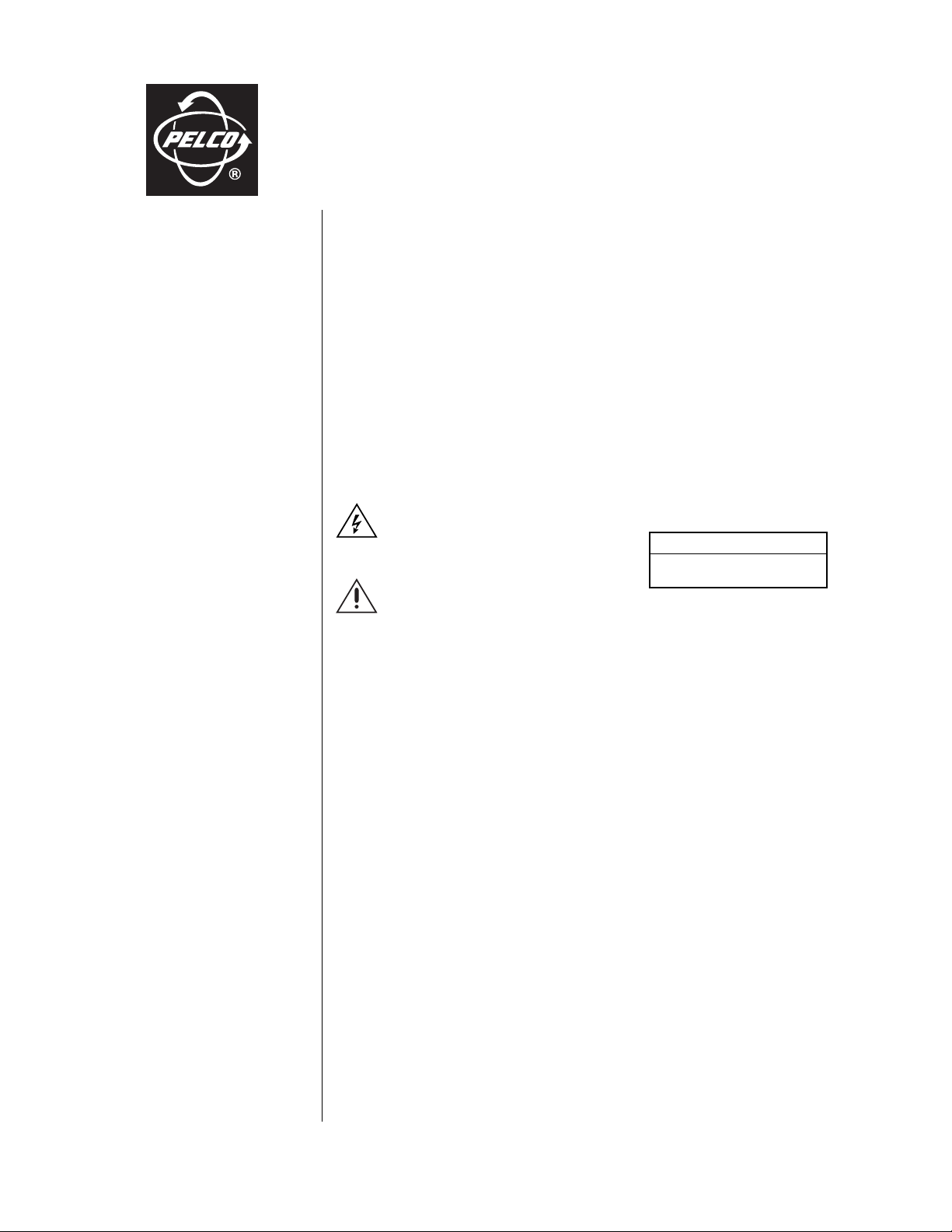
5. Mount the first camera and lens onto the adjustable mounting bracket. Adjust the position
of the camera and lens to clear the enclosure cover when closed. Tighten the mounting
bracket fastener. Mount the second camera and lens in the opposite direction and adjust
the position for the best view. Tighten the bracket fastener. (See Figure 1.)
6. Route the appropriate cables into the enclosure. Make all necessary electrical connections.
7. Close and lock the cover.
Figure 1. Camera Mounting Configuration
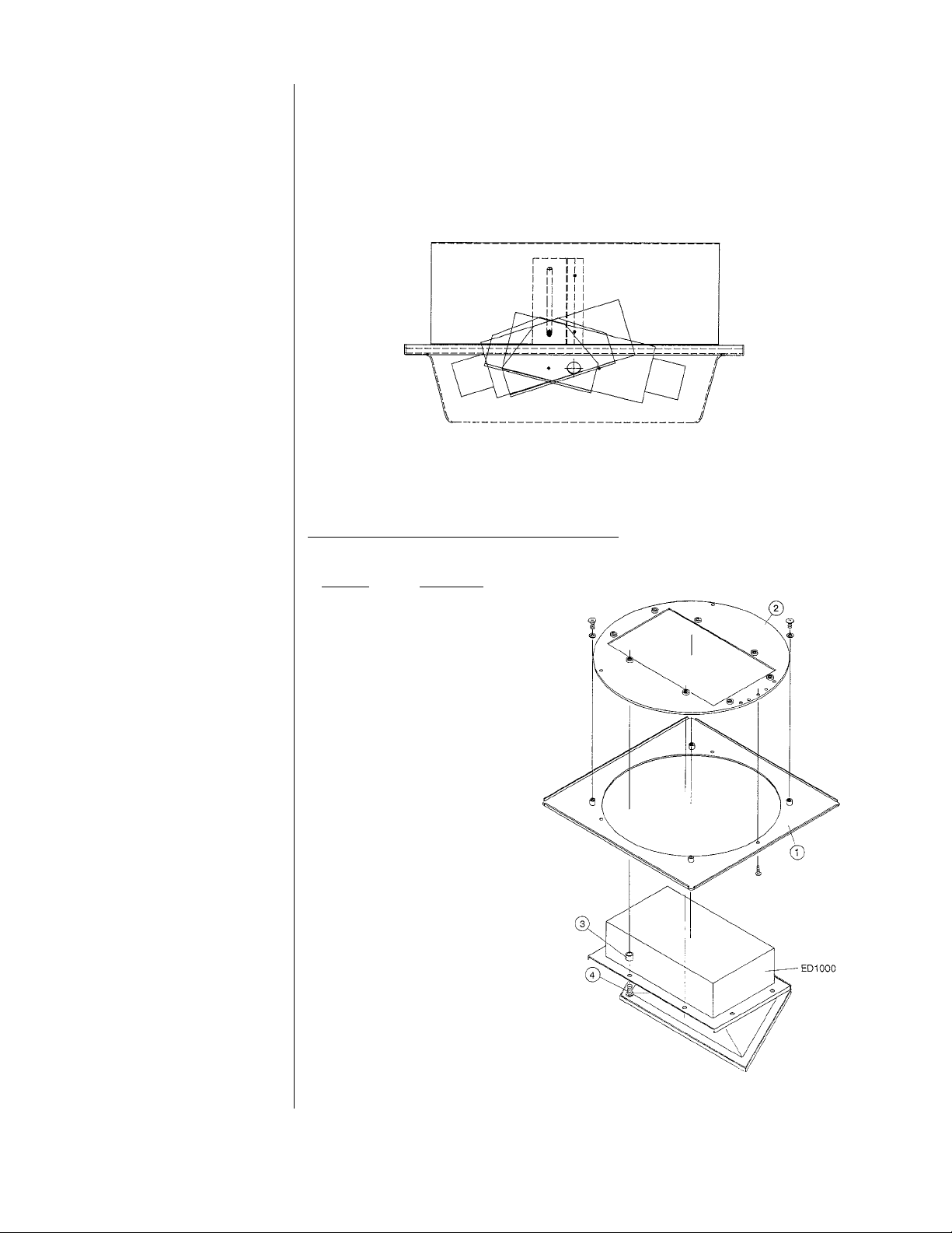
Installation Using E1003 Mounting Plate
The E1003 is supplied as follows:
Quantity Description
1 Plate, square
1 Plates, round
8 Spacers
8 Screws, 10-32 x 1"
To assemble the ED1000 Ceiling Enclosure
in the E1003 Mounting Plate, perform the
following steps. Refer to Figure 2.
1. Place the E1003 (square and round
plates, items 1 and 2) on a flat surface
with the painted surface up.
2. Open the lid of the enclosure
(ED1000) and insert the enclosure
into the rectangular opening.
3. Position the spacers (item 3) provided between the mounting flange
of the enclosure and the round plate
of the E1003, aligning them with the
eight mounting holes.
4. Secure the enclosure to the E1003
with the screws (item 4) provided,
making sure the screws pass through
the spacers. Tighten the hardware.
5. Mount the enclosure into the 2 ft x 2 ft
(60.96 cm x 60.96 cm) opening in the
ceiling.
6. Refer to steps 3, 5, 6, and 7 in the
previous section for final installation
instructions.
Figure 2. E1003 Mounting Plate Installation
Page 3

CARE AND MAINTENANCE
Regularly scheduled maintenance will prolong the operational life and appearance of the equipment.
CAUTION:
Do not
use water, liquid or spray
cleaners of any kind on
inner surface of the enclosure.
1. If dust or other debris accumulates on the inside of the lower enclosure, remove the particles with clean air pressure only. Compressed air cans are available from commercial
photographic equipment and supply dealers.
2. Clean the outer surface of the enclosure and inner surface of the viewing window with a
nonabrasive cleaning cloth and antistatic cleaner that is safe for use on acrylic plastic. Do
not use kerosene or similar substances that can scratch the surface.
Service Manual
To order replacement parts for your unit, obtain a service manual in one of the following ways:
• Go to Pelco’s web site at ftp://www.pelco.com and find service manual C403SM.
• Contact Pelco’s Literature Department and request service manual C403SM.
SPECIFICATIONS
MECHANICAL
Camera Mounting: Two adjustable mounting table brackets capable of supporting a maximum
weight of 10 lb (4.53 kg) each
Max. Camera/
Lens Size: Accepts camera/lens combinations (including BNC connector) up to:
4.50" H x 3.50" W x 15.00" L (11.43 cm x 8.89 cm x 38.10 cm)
Ceiling Mounting: Upper section flange-mounted to fixed ceiling or E1003 rotating mounting
plate for false ceilings
Cable Entry: Conduit knockouts
Lock: Key lock
GENERAL
Construction:
Upper section 5052-H32 aluminum
Lower section Vacuum-formed ABS plastic. Viewing window, Lucite® SAR (Super Abrasion
Color:
Upper section Alodine
Lower section White textured
Environment: Indoor; 32° to 120°F (0° to 49°C)
Dimensions: See Figure 3
Weight: 6 lb (2.73 kg)
Shipping Wt: 8 lb (3.6 kg)
Resistant acrylic)
(Design and product specifications subject to change without notice.)
Page 4

10.50
(26.67)
5.94
(15.09)
9.70
(24.64)
12.56
(31.90)
NOTE: VALUES IN PARENTHESES ARE CENTIMETERS;
ALL OTHERS ARE IN INCHES.
17.10
(43.43)
20.00
(50.80)
Figure 3. ED1000 Dimension Drawing
WARRANTY AND RETURN INFORMATION
WARRANTY
Pelco will repair or replace, without charge, any merchandise proved defective in material
or workmanship for a period of one year after the date of shipment.
Exceptions to this warranty are as noted below:
• Five years on FT/FR8000 Series fiber optic products.
• Three years on Genex® Series products (multiplexers, server, and keyboard).
• Three years on Camclosure® and fixed camera models, except the CC3701H-2,
CC3701H-2X, CC3751H-2, CC3651H-2X, MC3651H-2, and MC3651H-2X camera
models, which have a five-year warranty.
• Two years on standard motorized or fixed focal length lenses.
• Two years on Legacy®, CM6700/CM6800/CM9700 Series matrix, and DF5/DF8 Series
fixed dome products.
• Two years on Spectra®, Esprit®, ExSite™, and PS20 scanners, including when used in
continuous motion applications.
• Two years on Esprit® and WW5700 Series window wiper (excluding wiper blades).
• Eighteen months on DX Series digital video recorders, NVR300 Series network video
recorders, and Endura™ Series distributed network-based video products.months on DX
Series digital video recorders, NVR300 Series network video recorders, Endura™ Series
distributed network-based video products, and TW3000 Series twisted pair transmission
products.
• One year (except video heads) on video cassette recorders (VCRs). Video heads will be
covered for a period of six months.
• Six months on all pan and tilts, scanners or preset lenses used in continuous motion
applications (that is, preset scan, tour and auto scan modes).
Pelco will warrant all replacement parts and repairs for 90 days from the date of Pelco
shipment. All goods requiring warranty repair shall be sent freight prepaid to Pelco, Clovis,
California. Repairs made necessary by reason of misuse, alteration, normal wear, or
accident are not covered under this warranty.
Pelco assumes no risk and shall be subject to no liability for damages or loss resulting
from the specific use or application made of the Products. Pelco’s liability for any claim,
whether based on breach of contract, negligence, infringement of any rights of any party
or product liability, relating to the Products shall not exceed the price paid by the Dealer to
Pelco for such Products. In no event will Pelco be liable for any special, incidental or
consequential damages (including loss of use, loss of profit and claims of third parties)
however caused, whether by the negligence of Pelco or otherwise.
The above warranty provides the Dealer with specific legal rights. The Dealer may also
have additional rights, which are subject to variation from state to state.
If a warranty repair is required, the Dealer must contact Pelco at (800)289-9100 or
(559) 292-1981 to obtain a Repair Authorization number (RA), and provide the following
information:
1. Model and serial number
2. Date of shipment, P.O. number, Sales Order number, or Pelco invoice number
3. Details of the defect or problem
If there is a dispute regarding the warranty of a product which does not fall under the
warranty conditions stated above, please include a written explanation with the product
when returned.
Method of return shipment shall be the same or equal to the method by which the item
was received by Pelco.
RETURNS
In order to expedite parts returned to the factory for repair or credit, please call the factory
at (800) 289-9100 or (559) 292-1981 to obtain an authorization number (CA number if
returned for credit, and RA number if returned for repair).
All merchandise returned for credit may be subject to a 20% restocking and refurbishing
charge.
Goods returned for repair or credit should be clearly identified with the assigned CA or RA
number and freight should be prepaid. Ship to the appropriate address below.
If you are located within the continental U.S., Alaska, Hawaii or Puerto Rico, send goods
to:
If you are located outside the continental U.S., Alaska, Hawaii or Puerto Rico and are
instructed to return goods to the USA, you may do one of the following:
If the goods are to be sent by a COURIER SERVICE, send the goods to:
If the goods are to be sent by a FREIGHT FORWARDER, send the goods to:
Service Department
Pelco
3500 Pelco Way
Clovis, CA 93612-5699
Pelco
3500 Pelco Way
Clovis, CA 93612-5699 USA
Pelco c/o Expeditors
473 Eccles Avenue
South San Francisco, CA 94080 USA
Phone: 650-737-1700
Fax: 650-737-0933
REVISION HISTORY
Manual # Date Comments
C403M – Original version.
C403M-A 3/91 –
C403M-B 12/99 Revised to new format. Moved exploded assembly diagram and parts list to new maintenance/service manual (C403SM).
® Pelco, the Pelco logo, Spectra, Esprit, Genex, Legacy, and Camclosure are registered trademarks of Pelco.
™ Endura and ExSite are trademarks of Pelco.
® Lucite is a registered trademark of Lucite. © Copyright 1999, Pelco. All rights reserved.
 Loading...