

Page 1
®
EA2000
Half-Duplex Equalizing Amplifier
Installation/Operation Manual
C632M (2/88)
Pelco • 3500 Pelco Way, Clovis, CA 93612-5699 • USA • (800) 289-9100 or (1-559) 292-1981
FAX (800) 289-9150 or (1-559) 292-3827
International customers call (1-559) 292-1981 or FAX (1-559) 348-1120
Page 2

TABLE OF CONTENTS
Section Page
1.0 WARNINGS ........................................................................................................................................1
2.0 SCOPE ............................................................................................................................................... 2
3.0 DESCRIPTION ................................................................................................................................... 2
3.1 OPTIONS..................................................................................................................................2
4.0 INSTALLATION .................................................................................................................................. 2
5.0 OPERATION ......................................................................................................................................2
6.0 MAINTENANCE ................................................................................................................................. 3
7.0 PARTS LIST .......................................................................................................................................4
8.0 EXPLODED ASSEMBLY DIAGRAM ..................................................................................................5
9.0 SCHEMATIC ......................................................................................................................................6
10.0 SPECIFICATIONS .............................................................................................................................. 7
11.0 WARRANTY AND RETURN INFORMATION.....................................................................................8
®Pelco and the Pelco logo are registered trademarks of Pelco.
©Copyright 1988, Pelco. All rights reserved.
ii Pelco Manual C632M (2/88)
Page 3

LIST OF ILLUSTRATIONS
Figure Page
1 Typical Installation Configuration .................................................................................................... 3
2 EA2000 Cable Connections ............................................................................................................3
3 EA2000 Exploded Assembly Diagram ............................................................................................ 5
4 EA2000 Schematic (PCB9000104) ................................................................................................. 6
5 EA2000 Dimension Drawing ........................................................................................................... 7
Pelco Manual C632M (2/88) iii
Page 4

(This page intentionally left blank.)
iv Pelco Manual C632M (2/88)
Page 5
INSTALLATION/OPERATION MANUAL
MODEL EA2000
HALF-DUPLEX EQUALIZING AMPLIFIER
1.0 WARNINGS
Prior to installation and use of this product, the following
WARNINGS should be observed.
1. Installation and servicing should only be done by
Qualified Service Personnel and conform to all Local codes.
2. Unless the unit is specifically marked as a NEMA
Type 3, 3R, 35, 4, 4X, 6 or 6P enclosure, it is designed for Indoor use only and it must not be installed where exposed to rain and moisture.
3. The product may bear the following marks:
This symbol indicates that dangerous voltage
constituting a risk of electric shock is present
within this unit.
4. Only use replacement parts recommended by
Pelco.
5. After replacement/repair of this unit’s electrical
components, conduct a resistance measurement
between line and exposed parts to verify the exposed parts have not been connected to line circuitry.
This symbol indicates that there are important
operating and maintenance instructions in the
literature accompanying this unit.
CAUTION:
TO REDUCE THE RISK OF ELECTRICAL
SHOCK, DO NOT REMOVE COVER. NO
USER-SERVICEABLE PARTS INSIDE.
REFER SERVICING TO QUALIFIED
SERVICE PERSONNEL.
RISK OF ELECTRIC SHOCK.
CAUTION:
DO NOT OPEN.
Please thoroughly familiarize yourself with the information in this manual
prior to installation and operation.
Pelco Manual C632M (2/88) 1
Page 6

2.0 SCOPE
4.0 INSTALLATION
The information contained within this manual covers
the installation and operation of the EA2000 Half-duplex
Equalizing Amplifier.
3.0 DESCRIPTION
The EA2000 is a prioritized, half-duplex equalizing
amplifier intended for, but not restricted to, use with
Pelco’s Coaxitron
®
System 2000 control.
In the absence of a Coaxitron control signal, the amplifier functions identically to an ordinary unidirectional
equalizer, providing up tp 8 dB of flat gain and high
frequency boost of up to 18 dB at 12 MHz.
In the presence of a control signal, the “forward” equalizing function is temporarily suspended while the control signal is regenerated, pre-equalized and transmitted
in the “reverse” direction.
Note that the control direction has priority over the video
direction, but that this “interruption” occupies less than
one TV line period (excluding sync pulses) and that
precautions are taken to insure that the synthetically
generated video signal during this interruption does not
contain deleterious anomolies.
The EA2000 provides a low cost, highly effective means
of maintaining CCTV picture quality in runs of up to
3,000 feet (914 m) of RG59 cable.
Through panel controls provide for adjustable amplifier flat gain of 1-8 dB plus adjustable high frequency
boost of from 0 to greater than 18 dB at 12 MHz.
Applications of the EA2000 should be for postequalization only (located near the Coaxitron transmitter); use as a pre-equalizer is not allowed.
This desk top unit can be rack mounted using the R300
Rack Mount Kit.
3.1 OPTIONS
R300 Rack mount kit (up to 3 units can be
racked horizontally)
The EA2000 is designed to be used for post equalization only (located near the Coaxitron transmitter); use
as a pre-equalizer is not allowed.
Figure 1 illustrates a typical system installation.
For installation, perform the following steps:
1. Connect the video cable from the Coaxitron receiver to the connector marked “INPUT” on the
rear panel.
2. Connect a video cable from the connector marked
“OUTPUT” to the Coaxitron transmitter (see Figure 2).
The EA2000 is supplied with a U.L. listed wall transformer which plugs into a 120 VAC outlet and supplies
the 12 VAC to operate the unit.
5.0 OPERATION
Optimum performance is achieved if an oscilloscope
and a standard EIA resolution chart are used in making
gain and boost adjustments. The GAIN control should
be adjusted for an output level to 1 volt p-p and the L.F .
BOOST control should be adjusted for minimum tilt
during sync pulses. The H.F. BOOST control is then
adjusted for optimum resolution wedge reproduction.
If the use of a resolution chart is precluded, the H.F.
BOOST control should be adjusted for maximum sharpness of sync pulse edges — without overshoot.
In the absence of an oscilloscope, a less precise (but often
equally satisfactory) adjustment can be made as follows:
1. Set the GAIN and BOOST controls approximately
1/3 turn from fully counterclockwise.
2. Adjust GAIN control for satisfactory overall picture contrast.
3. Adjust L.F. BOOST control for optimum detail.
Too much boost (clockwise) can cause picture instability and/or smearing (trail).
4. Adjust the H.F. BOOST control to further optimize
picture detail. Note that the effectiveness of this
control is hardly perceptible unless very fine picture detail is present in the camera signal output.
An excessive setting of this control (clockwise) can,
however, increase picture noise.
2 Pelco Manual C632M (2/88)
Page 7

6.0 MAINTENANCE
Under normal operating conditions and usage, maintenance of this equipment is not necessary . The EA2000
has no operator serviceable components and should be
serviced by a trained technician or returned to the factory for repair.
TERMINATE
MONITOR
COAXIAL CABLE
COAXIAL CABLE
AC INPUT
F1 .2 ASB
MPT9000CZ TRANSMITTER
VIDEO
J8 J7 J6
COAXIAL
CABLE
OUTPUT INPUT
12 VAC
COAXIAL CABLE
AC INPUT
IN OUT
EA2000
COAXITRON® RECEIVER
Figure 1. Typical Installation Configuration
TO TRANSMITTER FROM RECEIVER
OUTPUT INPUT
MULTICONDUCTOR
CABLE
12 VAC
Figure 2. EA2000 Cable Connections
Pelco Manual C632M (2/88) 3
Page 8

7.0 PARTS LIST
The following list corresponds to the exploded assembly diagram in Figure 3.
Item Qty Description Part Number
1 1 Connector, DC power jack #16 PJ221 CON16PJ421
2 2 Connector MTA 2-position cable w/socket CON640428-2
3 1 Connector MTA 3-position cable w/socket CON640428-3
4 2 Connector, BNC CP1094ULNSD CAM00 CONUG1094/U
5 1 Chassis, univ M1CA M1CA4001COMP
6 1 Chassis cover, univ M1CA M1CA4001COMP
7 1 Panel front, EA2000 PANEA4004COMP
8 1 PCB assembly, half-duplex equalizer PCB9000104ASSY
9 1 Panel, rear EA2000 RPEA4000COMP
10 4 Spacer, 1/4" hex x .375 4-40 tap SPA8402
11 Not used
12 1 Lug, BNC ground ZH1497
13 2 Screw, 2-56 x 3/16" pan slot SS ZH2-56X.187SPS
14 8 Screw, 4-40 x 1/4" pan Philips SS ZH4-40X.250SPP15
15 8 Screw, 4-40 x 3/8" pan Philips Blk ZH4-40X.375BPP
16 4 Screw, 4-40 x 3/8" pan Philips SS ZH4-40X.375SPP
17 12 Washer, internal star #4 SS ZH4LWSIS
4 Pelco Manual C632M (2/88)
Page 9
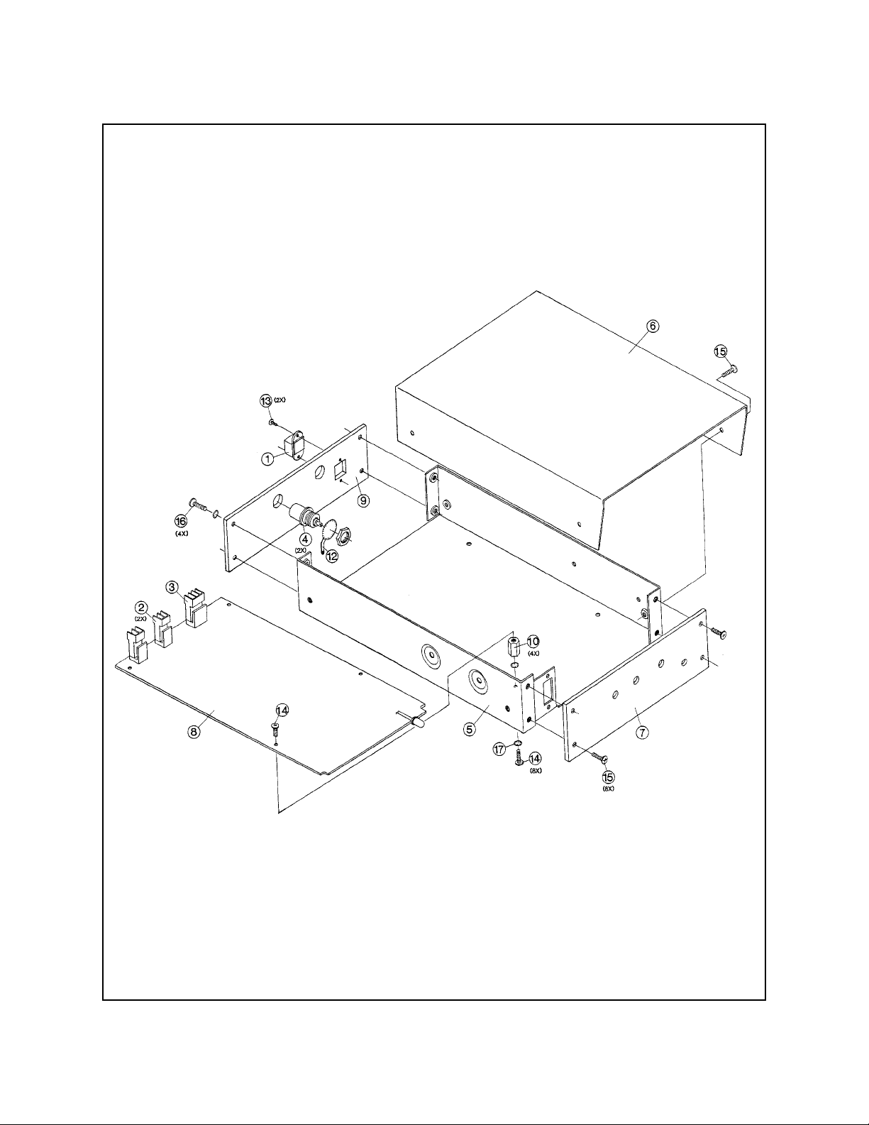
8.0 EXPLODED ASSEMBLY DIAGRAM
Figure 3. EA2000 Exploded Assembly Diagram
Pelco Manual C632M (2/88) 5
Page 10

9.0 SCHEMATIC
J2
+10
Q7
3638
1K
R34
R13
5.6K
C20
22Pf
Q8
330
R38
R36
33K
R37
R54
3.3K
+
C19
R52
3.3K
510
R39
47K
R40
GAIN
2
J3
OUTPUT
2
C17
+
R21
CR5
R32
6516
100
100/25V
CR8
C24
CW
R56
1
1
R26
75
22K
Q9
+
1000
470
R31
C25
+
3565
500
+
16V
C23
33
100
34
U2
3.3
R51
R46
R24
R23
Q6
3.3
R41
6.8K
25V
510
R2B
2.2K
2.2K
3565
35V
LO
27K
R55
R45
Q3
2.2K
Q1
R22
5.6K
10K
R10
C
Q4
CR7
CW
BOOST
220
100
3640
Q2
3565
R33
5
6516
R42
R43
100
R35
Q12
R44
R8
1.2K
R12
R11
1K
3565
C21
10K
560
5K
R27
3565
10K
680K
R53
.01
C
1K
R25
+
2.7K
.002
R20
HI
4.7K
C12
100/25V
C18
0.1/35V
.01
C14
C16
500
BOOST
+
220Pf
CW
Q11
C22
R49
CR6
2
U2
6516
+10
U4
C8
2
1/35V
C
4
R4
47K
C9
R5
18K
5
10
15
U4
+
14
C
1/35V
12
R19
10K
Q5
6516
R18
10K
1K
R16
14 538
14 538
11
R15
C11
C15
470K
9
.001
.001
Q
N/C
Q
R17
3
CR6
CR5
13
1K
UNLESS
7
1
NOTE: ALL DIODES IN914
R1
10K
10K
11
C
U2
10
R3
10K
12
Q
10
U3
C
4013
11
8
6
C
U2
9
C7
4 0 66
.001
OUT
VR1
IN
R6
+10
7810
47K
CR4
J1
R7
CR3
IN 4005
680
C13
+
C3
+
IN 4005
1
12 VAC
33
470
LEDI
25V
35V
CR1
IN 4005
CR2
IN 4005
C2
.01
C1
.01
2
3
13
1
22K
R14
12
R2
13
Q
Q
8
4
S
D
9
4
.002
75
R50
75
Q10
R47
6516
2
1
Q
6
S
U3
D
C
4013
3
5
R30
4.7K
R48
75
3.9K
R29
R29
75K
U1
10K
3
U1
4 0 11U14 0 11
4 0 11
U1
4 0 11
INPUT
Figure 4. EA2000 Schematic (PCB9000104)
6 Pelco Manual C632M (2/88)
Page 11
10.0 SPECIFICATIONS
MODEL
EA2000 Half-duplex Equalizing Video/Control
Amplifier. (UL)
EA2000/220 Same as EA2000 except 230 VAC
operation. (CE)
ELECTRICAL
Input: Single (BNC) internally terminated
in 75 ohms
Cable Lengths:
Cable Type Maximum Effective Distance
RG59 3,000 feet (914.4 m)
RG6 4,500 feet (1371.6 m)
RG11 6,000 feet (1828.8 m)
RG15 8,000 feet (2438.4 m)
GENERAL
Environment: 32° to 122°F (0 to 48.89°C)
0-90% relative humidity
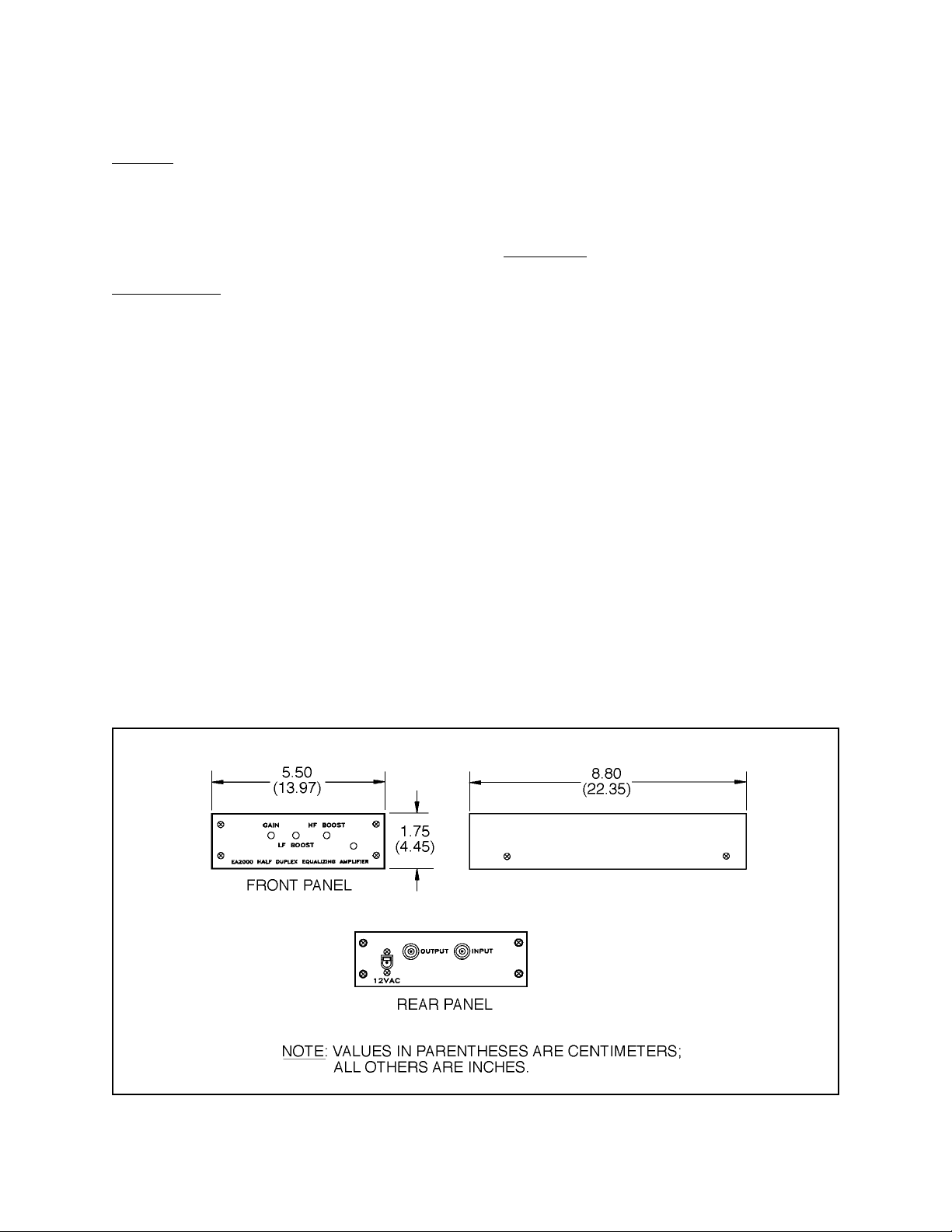
Dimensions: see Figure 5
Output: Single (BNC) source terminated
Frequency
Response: Adjustable from flat (±1 dB) at 12
MHz to greater than 18 dB of boost at
12 MHz
Gain: Adjustable from 1–8 dB
Output
Dynamic Range: Up to 2 volts p-p at 50% APL
Up to 1.5 volts p-p at 90% APL
Tilt: Less than 2%
Power Requirements
for Transformer: 1.5 vA (.125 amp) at 12 ±15% volts
RMS 50-60 Hz from a dedicated, isolated source
Weight: 3 lbs (1.35 kg)
Shipping
Weight: 4 lbs (1.81 kg)
Construction:
Chassis Steel, zinc plated
Cover Aluminum, black polyester powder
coat
Panel Aluminum, black polyester powder
coat with white silk screening
Rating: NEMA 1
Figure 5. EA2000 Dimension Drawing
Pelco Manual C632M (2/88) 7
Page 12

11.0 WARRANTY AND RETURN
INFORMATION
WARRANTY
Pelco will repair or replace, without charge, any merchandise proved
defective in material or workmanship for a period of one year after the date
of shipment.
Exceptions to this warranty are as noted below:
• Five years on FT/FR8000 Series fiber optic products.
• Three years on Genex
keyboard).
• Three years on Camclosure
CC3701H-2, CC3701H-2X, CC3751H-2, CC3651H-2X, MC3651H-2,
®
Series products (multiplexers, server, and
®
and fixed camera models, except the
and MC3651H-2X camera models, which have a five-year warranty.
• Two years on standard motorized or fixed focal length lenses.
• Two years on Legacy
DF5/DF8 Series fixed dome products.
• Two years on Spectra
ing when used in continuous motion applications.
• Two years on Esprit
wiper blades).
•
Eighteen months on DX Series digital video recorders, NVR300
Series network video recorders, and Endura
®
, CM6700/CM6800/CM9700 Series matrix, and
®
, Esprit®, ExSite™, and PS20 scanners, includ-
®
and WW5700 Series window wiper (excluding
™
Series distributed
network-based video products.
• One year (except video heads) on video cassette recorders (VCRs).
Video heads will be covered for a period of six months.
• Six months on all pan and tilts, scanners or preset lenses used in
continuous motion applications (that is, preset scan, tour and auto scan
modes).
Pelco will warrant all replacement parts and repairs for 90 days from the
date of Pelco shipment. All goods requiring warranty repair shall be sent
freight prepaid to Pelco, Clovis, California. Repairs made necessary by
reason of misuse, alteration, normal wear, or accident are not covered
under this warranty.
Pelco assumes no risk and shall be subject to no liability for damages or
loss resulting from the specific use or application made of the Products.
Pelco’s liability for any claim, whether based on breach of contract,
negligence, infringement of any rights of any party or product liability,
relating to the Products shall not exceed the price paid by the Dealer to
Pelco for such Products. In no event will Pelco be liable for any special,
incidental or consequential damages (including loss of use, loss of profit
and claims of third parties) however caused, whether by the negligence
of Pelco or otherwise.
The above warranty provides the Dealer with specific legal rights. The
Dealer may also have additional rights, which are subject to variation from
state to state.
If a warranty repair is required, the Dealer must contact Pelco at (800)2899100 or (559) 292-1981 to obtain a Repair Authorization number (RA),
and provide the following information:
1. Model and serial number
2. Date of shipment, P.O. number, Sales Order number, or Pelco invoice
number
3. Details of the defect or problem
If there is a dispute regarding the warranty of a product which does not fall
under the warranty conditions stated above, please include a written
explanation with the product when returned.
Method of return shipment shall be the same or equal to the method by
which the item was received by Pelco.
RETURNS
In order to expedite parts returned to the factory for repair or credit, please
call the factory at (800) 289-9100 or (559) 292-1981 to obtain an
authorization number (CA number if returned for credit, and RA number
if returned for repair).
All merchandise returned for credit may be subject to a 20% restocking
and refurbishing charge.
Goods returned for repair or credit should be clearly identified with the
assigned CA or RA number and freight should be prepaid. Ship to the
appropriate address below.
If you are located within the continental U.S., Alaska, Hawaii or Puerto
Rico, send goods to:
If you are located outside the continental U.S., Alaska, Hawaii or Puerto
Rico and are instructed to return goods to the USA, you may do one of the
following:
If the goods are to be sent by a COURIER SERVICE, send the goods to:
If the goods are to be sent by a FREIGHT FORWARDER, send the goods
to:
Service Department
Pelco
3500 Pelco Way
Clovis, CA 93612-5699
Pelco
3500 Pelco Way
Clovis, CA 93612-5699 USA
Pelco c/o Expeditors
473 Eccles Avenue
South San Francisco, CA 94080 USA
Phone: 650-737-1700
Fax: 650-737-0933
8 Pelco Manual C632M (2/88)
 Loading...