

Page 1
C415M-J (11/99)
E700 Series
Dust-Tight Enclosure
®
3500 Pelco Way,
Clovis, CA 93612-5699
USA
In North America & Canada:
Tel (800) 289-9100
FAX (800) 289-9150
International Customers:
Tel +1 (559) 292-1981
FAX +1 (559) 348-1120
www.pelco.com
IMPORTANT SAFEGUARDS AND WARNINGS
Prior to installation and use of this product, the following WARNINGS should be observed.
1. Installation and servicing should only be done by qualified service personnel and conform
to all local codes.
2. Unless the unit is specifically marked as a NEMA Type 3, 3R, 3S, 4, 4X ,6 or 6P enclosure, it is designed for indoor use only and it must not be installed where exposed to rain
and moisture.
3. Only use replacement parts recommended by Pelco.
4. After replacement/repair of this unit’s electrical components, conduct a resistance measurement between line and exposed parts to verify the exposed parts have not been connected to line circuitry.
The product and/or manual may bear the following marks:
This symbol indicates that dangerous voltage constituting a risk of
electric shock is present within
this unit.
This symbol indicates that there
are important operating and maintenance instructions in the literature accompanying this unit.
Please thoroughly familiarize yourself with the information in this manual prior to installation
and operation.
CAUTION:
RISK OF ELECTRIC SHOCK.
DO NOT OPEN.
NOTE:
Models with purge
fittings require a filtered
compressed air supply up
to 35 psi at 10 cfm to provide positive internal air
pressure circulation. Uses
1/4-inch NPT fittings.
DESCRIPTION
The E700 Series Dust-Tight Enclosure is designed to protect CCTV cameras operating in
small-particle and dusty environments. Stainless steel models are available for use in corrosive atmospheres.
Models
E706-16 6-inch diameter x 16-inch length (15.24 cm x 40.64 cm), aluminum con-
struction
E706-16P Same as E706-16, except with purge fittings (15.24 cm x 40.64 cm)
E706-16PS Same as E706-16P, except type 304 stainless steel construction
E706-16S Same as E706-16, except type 304 stainless steel construction
E706-24 6-inch diameter x 24-inch length (15.24 cm x 60.96 cm), aluminum con-
struction
E706-24P Same as E706-24, except with purge fittings
E706-24PS Same as E706-24P, except type 304 stainless steel construction
E706-24S Same as E706-24, except type 304 stainless steel construction
E708-24 8-inch diameter x 24-inch length (20.32 cm x 60.96 cm), aluminum con-
struction
E708-24P Same as E708-24, except with purge fittings
E708-24PS Same as E708-24P, except type 304 stainless steel construction
E708-24S Same as E708-24, except type 304 stainless steel construction
Page 2
INSTALLATION
Camera and Lens
To install the camera and lens, perform the following steps:
1. Unsnap the two latches holding the rear end plate on the enclosure and slide the camera
sled out.
2. Place the camera and lens at the maximum forward position on the sled. Adjust the
camera and lens so that they do not extend beyond the track. Attach camera and lens
with the 1/4-20 x .500-inch, hex head screws provided.
a. An enclosure with a heater, a camera with a low optical centerline, or a camera
using a large diameter lens may require an elevation block (EB1 or EB2) for proper
positioning.
b. Extend the lens to the maximum length before positioning the camera and lens
combination. This will ensure that the lens has enough clearance and will not hit the
window during focusing.
3. Loosen the cable gland nuts on the back of the enclosure. Route video and power cables
through separate glands and connect to the camera. Tighten the gland nuts for a snug fit
around the cables. Refer to Table A for the type of video coaxial cable to use. If the
camera uses 24 VAC, refer to Table B to determine the size of wire to use.
4. Close and secure the enclosure. Attach padlocks (not supplied) to the latches, if desired.
5. Attach the enclosure to the mount or pan/tilt. Follow the instructions provided with the
mounting equipment.
Table A. Video Coaxial Cable Requirements
Cable Type* Maximum Distance
RG59/U 750 ft (229 m)
RG6/U 1,000 ft (305 m)
RG11/U 1,500 ft (457 m)
* Minimum cable requirements:
75 ohms impedance
All-copper center conductor
All-copper braided shield with 95% braid coverage
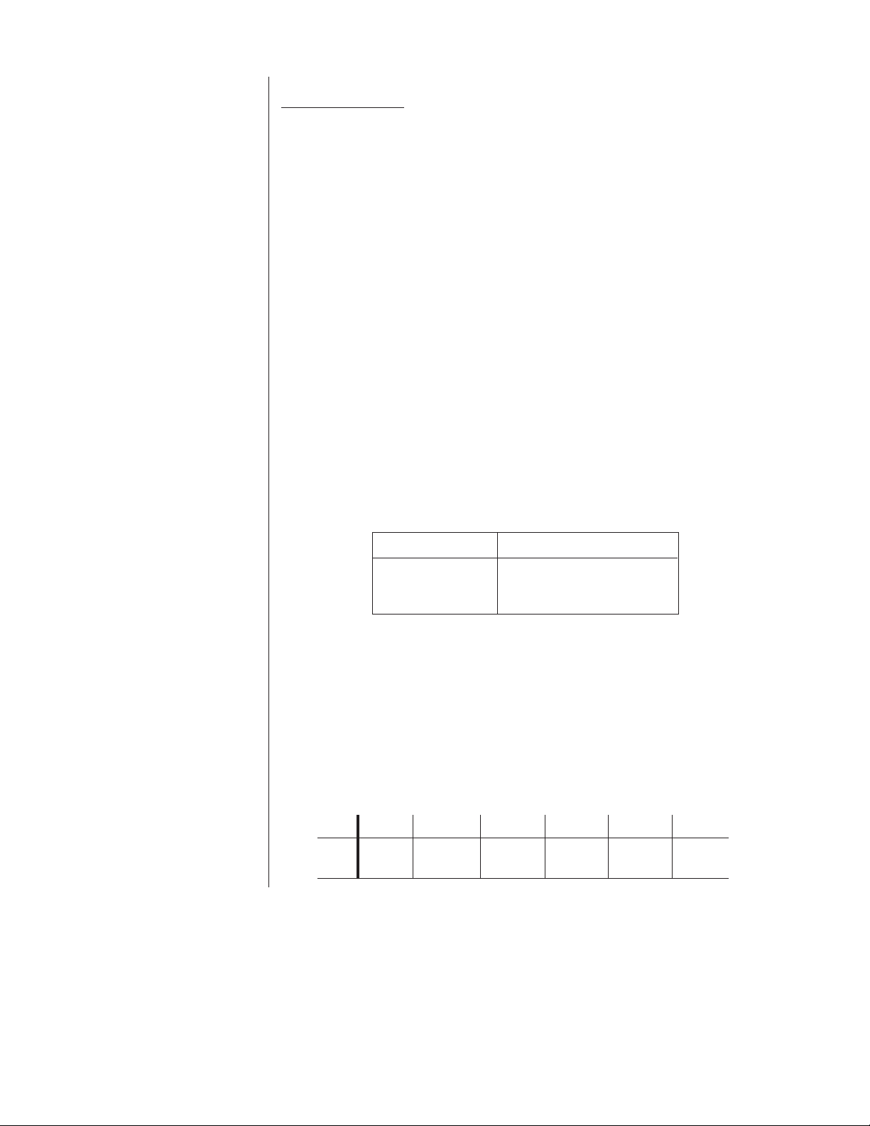
Table B. 24 VAC Wiring Distances
The following are the recommended maximum distances for 24 VAC applications and are calculated with a 10-percent voltage drop. (Ten percent is generally the maximum allowable voltage drop for AC-powered devices.)
Wire Gauge
20 18 16 14 12 10
10 vA 283 ft 451 ft 716 ft 1142 ft 1811 ft 2880 ft
(86 m) (137 m) (218 m) (348 m) (551 m) (877m)
Page 3

BACK COVER
CAMERA SLED
GLAND
CAUTION:
Do not
restrict exhaust outlet. Pressure may
build within the enclo-
sure and damage the window.
The E700 Series Enclosure is
not designed to be pressurized.
FRONT COVER
(WINDOW & RING)
LATCH
LATCH
Figure 1. Enclosure Assembly
Enclosures with Purge Fittings
Purge fittings create internal positive pressure, keeping external contaminants from entering
the enclosure. Proper installation requires a filtered compressed air supply up to 35 psi at 10
cfm. A refrigerated air supply will provide additional cooling for the enclosure. Models with
purge fittings come equipped with two .25-inch NPT female fittings located on the rear plate.
One is for air input and the other for exhaust. Either fitting can be used for input or exhaust.
Make the necessary connections.
MAINTENANCE
Regularly scheduled maintenance will help prolong the operational life and the appearance of
this equipment. The front window can be cleaned with any standard glazing cleaner. Avoid
abrasive cleaners. To access the inside of the window open the latches on the front plate.
SPECIFICATIONS
MECHANICAL
Camera Mounting: Multiple mounting holes in removable sled
Cable Entry: Two adjustable, liquid tight glands
Window: .187-inch (4.74 mm) thick Lucite® SAR acrylic
Latches: Draw latch with security features
GENERAL
Construction: Aluminum or type 304 stainless steel
Finish: Gray polyester powder coat
Weight Aluminum Stainless Steel
E706-16: 6 lb 14 oz. (3.11 kg) 13 lb (5.89 kg)
E706-24: 9 lb 13 oz. (4.45 kg) 16 lb 13 oz. (7.62 kg)
E708-24: 10 lb 8 oz. (4.76 kg) 17 lb 9 oz. (7.96 kg)
Rating: NEMA 4 (stainless steel models NEMA 4X)
(Design and product specifications subject to change without notice.)
Page 4

PRODUCT WARRANTY AND RETURN INFORMATION
WARRANTY
Pelco will repair or replace, without charge, any merchandise proved defective in material or
workmanship for a period of one year after the date of shipment.
Exceptions to this warranty are as noted below:
• Five years on FT/FR8000 Series fiber optic products.
®
• Three years on Genex
• Three years on Camclosure® and fixed camera models, except the CC3701H-2,
CC3701H-2X, CC3751H-2, CC3651H-2X, MC3651H-2, and MC3651H-2X camera models,
which have a five-year warranty.
• Two years on standard motorized or fixed focal length lenses.
• Two years on Legacy
fixed dome products.
• Two years on Spectra
continuous motion applications.
• Two years on Esprit
• Eighteen months on DX Series digital video recorders, NVR300 Series network video
recorders, and Endura
• One year (except video heads) on video cassette recorders (VCRs). Video heads will be
covered for a period of six months.
• Six months on all pan and tilts, scanners or preset lenses used in continuous motion
applications (that is, preset scan, tour and auto scan modes).
Pelco will warrant all replacement parts and repairs for 90 days from the date of Pelco
shipment. All goods requiring warranty repair shall be sent freight prepaid to Pelco, Clovis,
California. Repairs made necessary by reason of misuse, alteration, normal wear, or accident
are not covered under this warranty.
Pelco assumes no risk and shall be subject to no liability for damages or loss resulting from
the specific use or application made of the Products. Pelco’s liability for any claim, whether
based on breach of contract, negligence, infringement of any rights of any party or product
liability, relating to the Products shall not exceed the price paid by the Dealer to Pelco for
such Products. In no event will Pelco be liable for any special, incidental or consequential
damages (including loss of use, loss of profit and claims of third parties) however caused,
whether by the negligence of Pelco or otherwise.
The above warranty provides the Dealer with specific legal rights. The Dealer may also have
additional rights, which are subject to variation from state to state.
Series products (multiplexers, server, and keyboard).
®
, CM6700/CM6800/CM9700 Series matrix, and DF5/DF8 Series
®
, Esprit®, ExSite™, and PS20 scanners, including when used in
®
and WW5700 Series window wiper (excluding wiper blades).
™
Series distributed network-based video products.
If a warranty repair is required, the Dealer must contact Pelco at (800) 289-9100 or
(559) 292-1981 to obtain a Repair Authorization number (RA), and provide the following
information:
1. Model and serial number
2. Date of shipment, P.O. number, Sales Order number, or Pelco invoice number
3. Details of the defect or problem
If there is a dispute regarding the warranty of a product which does not fall under the
warranty conditions stated above, please include a written explanation with the product
when returned.
Method of return shipment shall be the same or equal to the method by which the item was
received by Pelco.
RETURNS
In order to expedite parts returned to the factory for repair or credit, please call the factory at
(800) 289-9100 or (559) 292-1981 to obtain an authorization number (CA number if returned
for credit, and RA number if returned for repair).
All merchandise returned for credit may be subject to a 20% restocking and refurbishing
charge.
Goods returned for repair or credit should be clearly identified with the assigned CA or RA
number and freight should be prepaid. Ship to the appropriate address below.
If you are located within the continental U.S., Alaska, Hawaii or Puerto Rico, send goods to:
Service Department
Pelco
3500 Pelco Way
Clovis, CA 93612-5699
If you are located outside the continental U.S., Alaska, Hawaii or Puerto Rico and are
instructed to return goods to the USA, you may do one of the following:
If the goods are to be sent by a COURIER SERVICE, send the goods to:
Pelco
3500 Pelco Way
Clovis, CA 93612-5699 USA
If the goods are to be sent by a FREIGHT FORWARDER, send the goods to:
Pelco c/o Expeditors
473 Eccles Avenue
South San Francisco, CA 94080 USA
Phone: 650-737-1700
Fax: 650-737-0933
REVISION HISTORY
Manual # Date Comments
C415M-H 5/96 Revision H. Revised to show redesigned heater bracket configurations and heater pads or blankets per ECO #96-131 and 96-
C415M-I 6/98 Revision I. Removed E704 and E710 models, changed heater bracket design, added packing material to E706 air funnel kit.
C415M-J 11/99 Revision J. Created separate manuals for the Heater/Blower (C2412M), Sun Visor/Shroud (C2413M), and Air Funnel Kit
Pelco, the Pelco logo, Camclosure, Esprit, Genex, Legacy, and Spectra are registered trademarks of Pelco. © Copyright 1999, Pelco. All rights reser ved.
Endura and ExSite are trademarks of Pelco.
Lucite is a registered trademark of DuPont.
157. Part callouts for heater kits and options updated.
Changed manual to new format.
(C2414M). Updated manual to new format.
 Loading...