

Page 1
®
DF5 Series
DF5S Series
Fixed-Mount
Domes
Maintenance/
Service Manual
C1458SM-A (10/98)
Pelco • 300 W. Pontiac Way, Clovis • CA 93612-5699 USA • Pelco Online @ http://www.pelco.com
In North America and Canada: Tel (800) 289-9100 or FAX (800) 289-9150 • DataFAX (800) 289-9108
International Customers: Tel (1-559) 292-1981 or FAX (1-559) 348-1120 • DataFAX (1-559) 292-0435
Page 2

CONTENTS
Section Page
1.0 GENERAL ............................................................................................3
2.0 DESCRIPTION ....................................................................................4
3.0 MAINTENANCE ...................................................................................5
4.0 EXPLODED ASSEMBLY DIAGRAMS .................................................6
5.0 WARRANTY AND RETURN INFORMATION ....................................18
1.1 IMPORTANT SAFEGUARDS AND WARNINGS .......................3
2.1 MODELS....................................................................................4
LIST OF ILLUSTRATIONS
Figure Page
1 Exploded Assembly Diagram–DF5 In-Ceiling Models .........................6
2 Exploded Assembly Diagram–DF5C and DF5M In-Ceiling Models .....7
3 Exploded Assembly Diagram–DF5-0F and DF5-1F Flat Disk Models ...9
4 Exploded Assembly Diagram–DF5 Pendant Models (Original Version) ....10
5 Exploded Assembly Diagram-DF5 Pendant Models (Newer Version) ....11
6 Exploded Assembly Diagram–DF5C and DF5M Pendant Models...... 13
7 Exploded Assembly Diagram–Heater Segment in Pendant Back Box ...15
8 Exploded Assembly Diagram–Heater Segment in Pendant Lower Dome .16
9 Exploded Assembly Diagram–Sun Shield ..........................................16
10 Exploded Assembly Diagram–DF5S ...................................................17
LIST OF TABLES
Table Page
A Exploded Assembly Parts List–DF5 In-Ceiling Models.........................6
B Exploded Assembly Parts List–DF5C and DF5M In-Ceiling Models ....8
C Exploded Assembly Parts List–DF5-0F and DF5-1F Models ...............9
D Exploded Assembly Parts List–DF5 Pendant Models
(Original Version) .................................................................................12
E Exploded Assembly Parts List–DF5 Pendant Models (Newer Version) .12
F Exploded Assembly Parts List–DF5C and DF5M Pendant Models .....14
G Exploded Assembly Parts List–Heater Segment in Pendant Back Box .15
I Exploded Assembly Parts List–Sun Shield ..........................................16
H Exploded Assembly Parts List–Heater Segment in Pendant Lower
Dome ...................................................................................................16
J Exploded Assembly Parts List–DF5S ..................................................17
REVISION HISTORY
Manual # Date Comments
C1458SM 2/98 Original version.
5/98 Revised model numbers. Changed description and part
C1458SM-A 10/98 Revised Tables A, B, F, I, and J. Added Figures 3 and 5
number of item 3 in Table E.
and Tables C and E.
2 Pelco Manual C1458SM-A (10/98)
Page 3
1.0 GENERAL
1.1 IMPORTANT SAFEGUARDS AND WARNINGS
Prior to installation and use of this product, the following WARNINGS should be
observed.
1. Installation and servicing should only be done by qualified service personnel
and conform to all local codes.
2. Unless the unit is specifically marked as a NEMA Type 3, 3R, 3S, 4, 4X, 6, or
6P enclosure, it is designed for indoor use only and it must not be installed
where exposed to rain and moisture.
3. Only use replacement parts recommended by Pelco.
4. After replacement/repair of this unit’s electrical components, conduct a resistance measurement between line and exposed parts to verify the exposed
parts have not been connected to line circuitry.
5. The installation method and materials should be capable of supporting four
times the weight of the enclosure, pan/tilt, camera and lens combination.
The product and/or manual may bear the following marks:
This symbol indicates that dangerous voltage constituting a
risk of electric shock is present within this unit.
This symbol indicates that there are important operating and
maintenance instructions in the literature accompanying this
unit.
CAUTION:
RISK OF
ELECTRIC SHOCK.
DO NOT OPEN.
TO REDUCE THE RISK OF ELECTRICAL SHOCK,
DO NOT REMOVE COVER. NO USER-
SERVICEABLE P ARTS INSIDE. REFER SERVICING
TO QUALIFIED SERVICE PERSONNEL.
CAUTION:
Please thoroughly familiarize yourself with the information
in this manual prior to installation and operation.
Pelco Manual C1458SM-A (10/98) 3
Page 4
2.0 DESCRIPTION
DF5 Series domes are discreet surveillance domes that are designed for indoor or
outdoor use. Models include pendant and in-ceiling versions.
The DF5S Series domes are similar to the DF5 Series. The basic difference is that
the back box for the DF5 Series is 5.25 inches (13.34 cm) in height while the DF5S
Series back box is 2.75 inches (7 cm) in height. The DF5S Series domes are designed for indoor use where there is very little space above the ceiling.
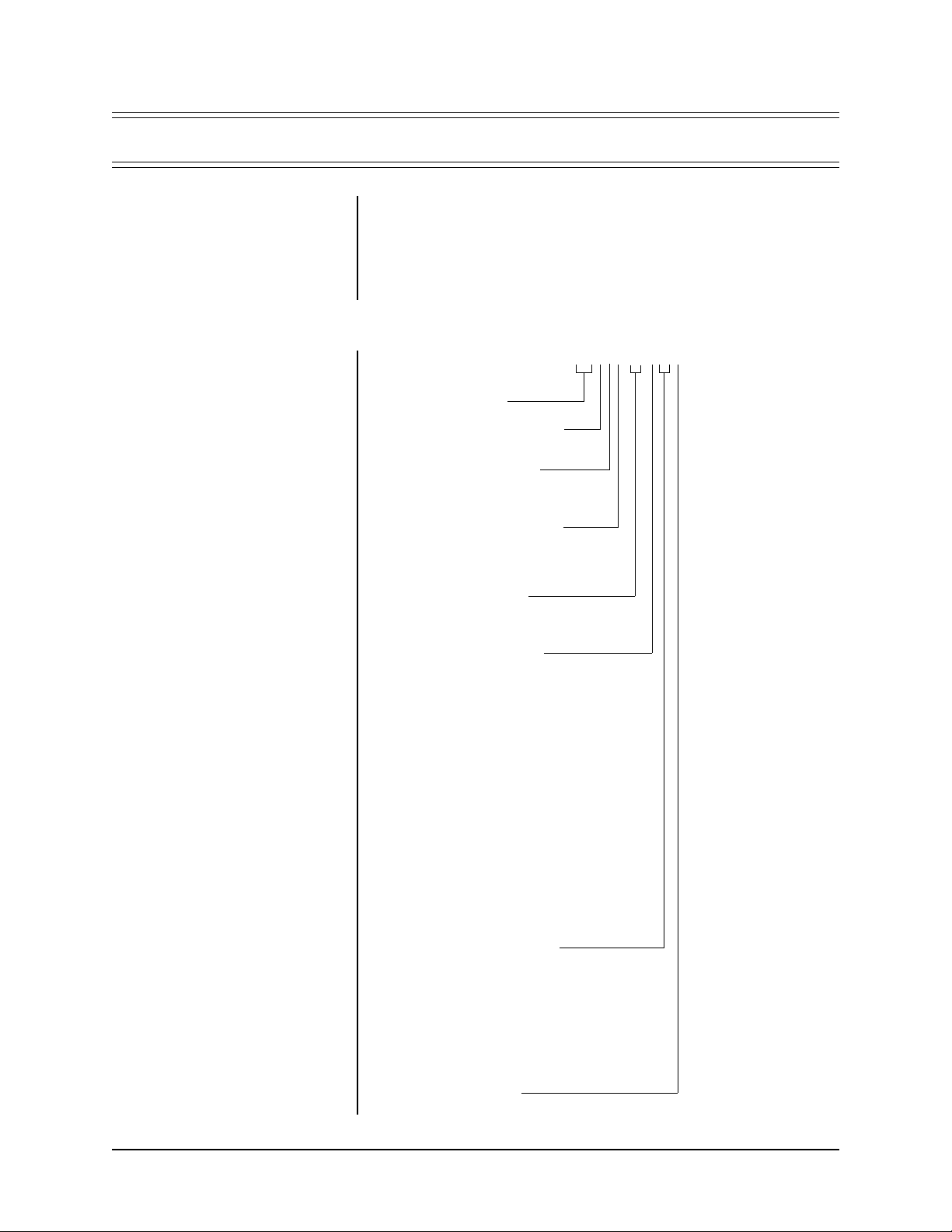
2.1 MODELS
NOTE:
Newer models furnished
with a camera have a 1/3-inch format camera.
Older models furnished with a camera have a 1/2-inch format camera
(models without an "X" at the end of
the model number have an EIA or
NTSC camera; models with an "X"
at the end of the model number have
a CCIR or PAL camera).
DF5SCA-PG-02.3A
DF5 Series Dome
S = Short in-ceiling back box
Blank = If not S
C = Color camera
M = Monochrome camera
Blank = No camera
A = 24 VAC camera power
NTSC standard (color)
EIA standard (monochrome)
Blank = No camera
PG = Pendant, gray
PB = Pendant, black
Blank = If not PG or PB
0 = Smoked dome
(1/2 f-stop of light loss)
1 = Clear dome
2 = Chrome dome
(2 f-stops of light loss)
3 = Gold dome
(2 f-stops of light loss)
EO = Outdoor pendant
(includes heater and
sun shield), light gray,
smoked dome (1/2
f-stop of light loss)
EI = Outdoor pendant
(includes heater and
sun shield), light gray,
clear dome
0F = Flat glass, smoked
(1/2 f-stop of light loss)
1F = Flat glass, clear
2.3 = 2.3 mm lens
2.8 = 2.8 mm lens
4 = 4 mm lens
8 = 8 mm lens
V2 = 2.5-6 mm varifocal lens
V3 = 3-8 mm varifocal
V35 = 3.5-8 mm varifocal
V5 = 5-40 mm varifocal
Blank = No lens
A = Auto iris
Blank = Manual iris
4 Pelco Manual C1458SM-A (10/98)
Page 5

3.0 MAINTENANCE
Clean the acrylic dome as necessary to maintain a clear picture. Be careful not the
scratch the surfaces of the dome.
Exterior Surface - Clean the dome’s exterior surface with a nonabrasive cleaning
cloth and cleaning agent that is safe for acrylic plastic. Either liquid or spray cleaner/
wax suitable for fine furniture is acceptable.
Interior Surface (Except Chrome or Gold) - Clean the same as the exterior surface.
Interior Surface (Chrome or Gold) - The inside surface of a chrome or gold dome
is easily scratched. Use the following precautions to maintain the dome’s surface.
A. Always handle the dome from the outside of its circular flange.
B. Never touch the coated inside surface. The acid in your fingerprints will even-
tually etch the coating if the fingerprints are not carefully removed according
to the recommended cleaning procedure in item E.
C. If dust or other contaminants accumulate on the dome’s interior, remove the
debris with compressed air. Compressed air cans are available from photographic equipment or electronic supply dealers.
D. If heavy residue accumulates and cannot be removed with air pressure, rinse
with water and immediately dry with air pressure so that water spots will not
remain. Avoid wiping the coated surface with direct hand pressure - it will easily
abrade unless extreme care is taken. Once scratched, the dome cannot be
recoated.
E. If internal wiping is necessary, avoid hand rubbing. Instead, make a wick as
follows:
Use a very soft paper towel. Roll a section into a tightly wound tube. Tear the
tube in half, and wet the fuzzy end of the wick with a solution of isopropyl
alcohol diluted with water. Hold the dome with its opening facing downward
and wipe the interior of the dome with the wet end of the wick. Use a circular
motion, starting from the outside and spiraling into the center. Use a new wick
for each two passes over the dome.
Pelco Manual C1458SM-A (10/98) 5
Page 6
4.0 EXPLODED ASSEMBLY DIAGRAMS
6
16
12
14
4
5
2
18
7
15
9
13
10
3
1
11
8
17
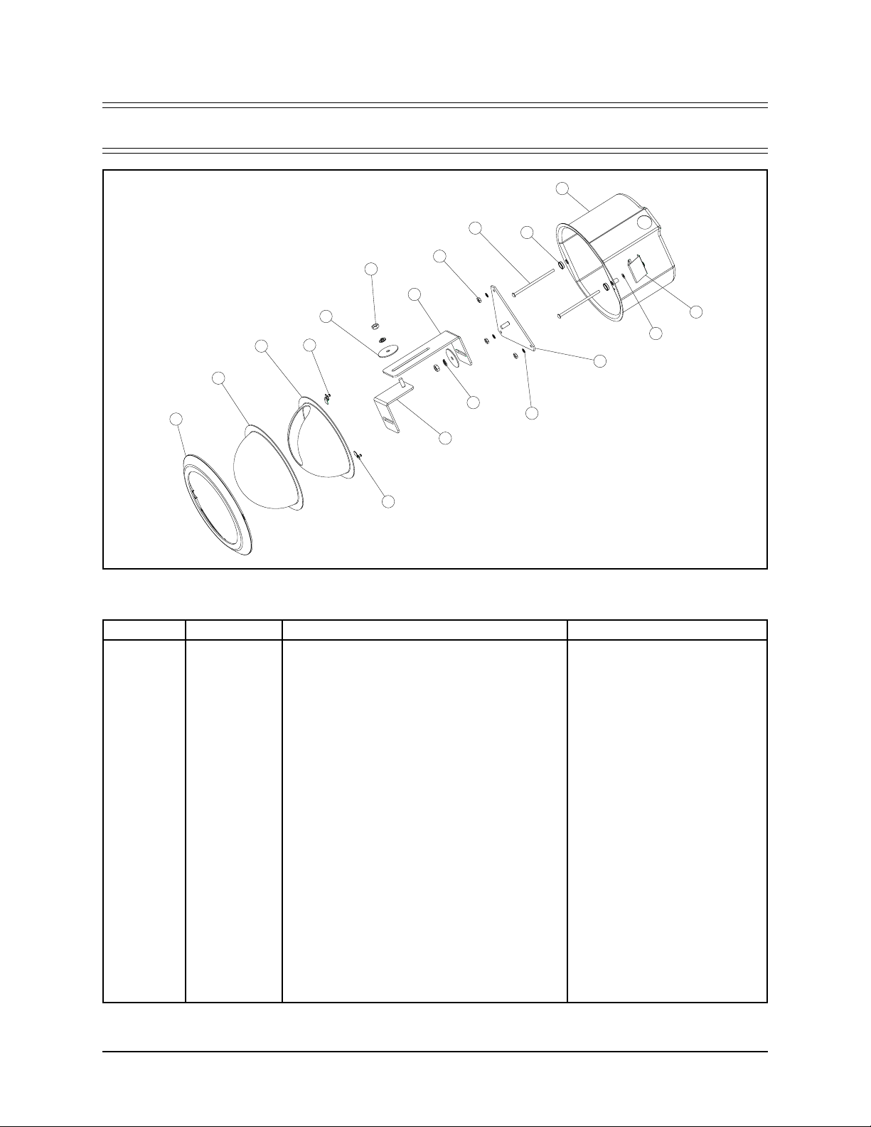
Figure 1. Exploded Assembly Diagram–DF5 In-Ceiling Models Table A. Exploded Assembly Parts List–DF5 In-Ceiling Models
Item Quantity Description Part Number
1 2 Spring paddle 70610027
2 1 Trim ring 70610030
3 2 Trim ring snap washer 70610036
4* 1 Dome liner 70610046
5 1 Acrylic dome (smoked) 70610015-04
6 1 Back box 7064020COMP
7* 2 Dome liner retainer 7064038COMP
8 1 Base plate DF54000COMP
9 1 Tilt table support leg DF54001COMP
10 1 Tilt table DF54002COMP
11 2 Push nut bolt retainer ZH810000
12 2 Nut, 1/4-20 ZH1/4-20NUTCH
13 3 Split lock washer, 1/4" ZH1/4LWSSL
14 2 Fender washer, 1/4" ZH255X1.50X62
15 3 Nut, 8-32 ZH8-32NUTSH
16 2 Screw, 8-32 x 3-1/2", pan head, Phillips ZH8-32X3.50SPP
17 3 Internal star washer, #8 ZH8LWSIS
18* 2 Screw, M3 x 5, pan head, black ZHM3X5BPT
NS 1 Flat washer, 3/16" ZH260X562X65C
NS 1 Screw, 1/4-20 x 1/2", hex ZH1/4-20X.500CH
NS 1 Conduit fitting 70610040
NS 1 Safety chain bracket 7064014COMP
NS 1 Trim ring leash assembly 7061010
NS = Not shown * Required with clear dome only
Acrylic dome (clear) 70610015-05
Acrylic dome (chrome) 70610005-02
Acrylic dome (gold) 70610005-03
6 Pelco Manual C1458SM-A (10/98)
Page 7

Figure 2. Exploded Assembly Diagram–DF5C and DF5M In-Ceiling Models
Pelco Manual C1458SM-A (10/98) 7
Page 8

T able B. Exploded Assembly Parts List–DF5C and DF5M In-Ceiling Models
Item Quantity Description Part Number
1 2 Spring paddle 70610027
2 1 Trim ring 70610030
3 2 Trim ring snap washer 70610036
4 1 Conduit fitting 70610040
5* 1 Dome liner 70610046
6 1 Acrylic dome (smoked) 70610015-04
7 1 Safety chain bracket 7064014COMP
8* 2 Dome liner retainer 7064038COMP
9 1 Back box 7064040COMP
10 1 Camera mount DF54003COMP
11 1 Camera/circuit board mount DF54004COMP
12 1 Tilt table DF54005COMP
13 1 Small circuit board bracket DF54006COMP
14 1 Circuit board cover DF54007COMP
15 1 Tilt table base plate DF54008COMP
16 1 Camera, B&W, high resolution, 24 VAC, 1/2" SC-BPL27
17 6 Spacer SPA9161
18 2 Push nut bolt retainer ZH810000
19 3 Nut, 1/4-20 ZH1/4-20NUTCH
20 3 Split lock washer, 1/4" ZH1/4LWSSL
21 2 Flat washer ZH125X312X32S
22 8 Nut, 2-56 ZH2-56NUTSH
23 2 Screw, 2-56 x 5/16", pan head, Phillips ZH2-56X.312SPP
24 2 Screw, 2-56 x 7/16", pan head, Phillips ZH2-56X.437SPP
25 4 Screw, 2-56 x 1/2", pan head, Phillips ZH2-56X.500SPS
26 4 Flat washer ZH260X562X65C
27 8 Internal tooth lock washer, #2 ZH2LWSIS
28 2 Screw, 4-40 x 3/16", pan head, Phillips ZH4-40X.187SPP
29 3 Nut, 8-32 ZH8-32NUTSH
30 2 Screw, 8-32 x 3-1/2", pan head, Phillips ZH8-32X3.50SPP
31 3 Internal tooth lock washer, #8 ZH8LWSIS
32 3 Screw, M2 x 6, pan head, Phillips ZHM2X6P.5SPP
33* 2 Screw, M3 x 5, pan head, black ZHM3X5BPT
NS 1 Trim ring leash assembly 7061010
Acrylic dome (clear) 70610015-05
Acrylic dome (chrome) 70610005-02
Acrylic dome (gold) 70610005-03
Camera, color, high resolution, 24 VAC, 1/2" SC-CPL27
NS = Not shown
* Required with clear dome only
8 Pelco Manual C1458SM-A (10/98)
Page 9

5
12
9
10
6
11
13
4
2
7
3
1
8
14
Figure 3. Exploded Assembly Diagram–DF5-0F and DF5-1F Flat Disk Models
Table C. Exploded Assembly Parts List–DF5-0F and DF5-1F Models
Item Quantity Description Part Number
1 2 Spring paddle 70610027
2 1 Trim ring 70610030
3 2 Trim ring snap washer 70610036
4 1 Acrylic flat disk (smoked) or 70610050-04
Acrylic flat disk (clear) 70610050-05
5 1 Back box 7064022COMP
6 1 Tilt table support leg DF54012COMP
7 1 Tilt table DF54002COMP
8 2 Push nut bolt retainer ZH810000
9 1 Nut, 1/4-20 ZH1/420NUTCHN
10 2 Split lock washer, 1/4" ZH1/4LWSSL
11 3 Fender washer, 1/4" ZH255X1.50X62
12 2 Screw, 8-32 x 3-1/2", pan head, Phillips ZH8-32X3.50SPP
13 1 Screw, M3 x 5, pan head, black ZHM3X5BPT
14 2 Screw, 1/4-20 x 1/2" hex ZH1/4-20X.500CH
NS 1 Conduit fitting 70610040
NS 1 Conduit knock out seal 70610048
NS 1 Safety chain bracket 7064014COMP
NS 1 Trim ring leash assembly 7061010
NS = Not shown
Pelco Manual C1458SM-A (10/98) 9
Page 10

Figure 4. Exploded Assembly Diagram–DF5 Pendant Models (Original Version)
10 Pelco Manual C1458SM-A (10/98)
Page 11

19
5
6
15
3
13
10
11
9
2
16
1
18
14
17
7
12
8
4
Figure 5. Exploded Assembly Diagram-DF5 Pendant Models (Newer Version)
Pelco Manual C1458SM-A (10/98) 11
Page 12

Table D. Exploded Assembly Parts List–DF5 Pendant Models (Original Version)
Item Quantity Description Part Number
1 1 Gasket 70610012
2 1 Acrylic dome (smoked) 70610015-04
3 1 Top mount, black 7064016BCOMP
4 1 Trim ring, black 7064023BCOMP
5 1 Lower dome retainer 7064027COMP
6 1 Back box, black 7064034BCOMP
7 1 Tilt table support leg DF54001COMP
8 1 Tilt table DF54002COMP
9 1 Base plate PDF54000COMP
10 2 Nut, 1/4-20 ZH1/4-20NUTCH
11 2 Split lock washer, 1/4" ZH1/4LWSSL
12 6 Fender washer, #6 x 5/8" ZH20-6X5/8"SS
13 2 Fender washer, 1/4" ZH255X1.50X62
14 6 Screw, 6-32 x 1/4", pan head, Phillips ZH6-32X.250SPP
15 2 Screw, 6-32 x 1/4", pan head, Phillips, black ZH6-32X.250BPP
16 1 O-ring ZH69-EP8X.139
17 6 Internal tooth lock washer, #6 ZH6LWSIS
18 3 Nut, 8-32 ZH8-32NUTSH
19 3 Screw, 8-32 x 3/8", pan head, Phillips ZH8-32X.375SPP
20 6 Internal tooth lock washer, #8 ZH8LWSIS
NS 1 Trim ring leash assembly 7061005
NS 1 Top mount adapter (pipe nipple), black 7064028BCOMP
NS 1 Trim ring gasket 94510030
Acrylic dome (clear) 70610015-05
Top mount, gray 7064016GCOMP
Trim ring, gray 7064023GCOMP
Back box, gray 7064034GCOMP
Screw, 6-32 x 5/16", pan head, Phillips, gray ZH6-32X.312GRAY
Top mount adapter (pipe nipple), gray 7064028GCOMP
Table E. Exploded Assembly Parts List–DF5 Pendant Models (Newer Version)
Item Quantity Description Part Number
1 1 Gasket 70610012
2 1 Lower dome retainer 70610019
3 1 Acrylic dome (smoked) 70610015-04
4 1 Trim ring, black 7064023BCOMP
5 1 Top mount, black 7064032BCOMP
6 1 Back box, black 7064034BCOMP
7 1 Tilt table support leg DF54001COMP
8 1 Tilt table DF54002COMP
9 1 Base plate PDF54000COMP
10 2 Nut, 1/4-20 ZH1/4-20NUTCH
11 2 Split lock washer, 1/4" ZH1/4LWSSL
12 2 Fender washer, 1/4" ZH255X1.50X62
13 6 Screw, 6-32 x 1/4", pan head, Phillips ZH6-32X.250SPP
14 2 Screw, 6-32 x 1/4", pan head, Phillips, black ZH6-32X.250BPP
15 1 O-ring ZH69-EP8X.139
16 6 Internal tooth lock washer, #6 ZH6LWSIS
17 3 Nut, 8-32 ZH8-32NUTSH
18 3 Screw, 8-32 x 3/8", pan head, Phillips ZH8-32X.375SPP
19 6 Internal tooth lock washer, #8 ZH8LWSIS
NS 1 Trim ring leash assembly 7061005
NS 1 Trim ring gasket 94510030
Acrylic dome (clear) 70610015-05
Acrylic dome (chrome) 70610005-02
Acrylic dome (gold) 70610005-03
Trim ring, gray 7064023GCOMP
Top mount, gray 7064032GCOMP
Back box, gray 7064034GCOMP
Screw, 6-32 x 5/16", pan head, Phillips, gray ZH6-32X.312GRAY
NS = Not shown
12 Pelco Manual C1458SM-A (10/98)
Page 13

3
1
26
31
10
32
24
13
27
29
22
11
15
8
18
23
21
28
25
30
7
33
19
9
6
20
12
17
14
5
2
4
16
Figure 6. Exploded Assembly Diagram–DF5C and DF5M Pendant Models
Pelco Manual C1458SM-A (10/98) 13
Page 14

Table F. Exploded Assembly Parts List– DF5C and DF5M Pendant Models
Item Quantity Description Part Number
1 1 Gasket 70610012
2 1 Acrylic dome (smoked) 70610015-04
3* 1 Top mount, black 7064016BCOMP
4 1 T rim ring, black 7064023BCOMP
5** 1 Lower dome retainer 7064027COMP
6 1 Back box, black 7064034BCOMP
7 1 Tilt table DF54005COMP
8 1 Circuit board cover DF54007COMP
9 1 Base plate PDF54000COMP
10 1 Camera mount DF54003COMP
11 1 Camera/circuit board mount DF54004COMP
12*** 6 Fender washer, #6 x 5/8" ZH20-6X5/8"SS
13 1 Small circuit board bracket DF54006COMP
14 6 Screw, 6-32 x 1/4", pan head, Phillips ZH6-32X.250SPP
15 2 Screw, 6-32 x 1/4", pan head, Phillips, black ZH6-32X.250BPP
16 1 O-ring ZH69-EP8X.139
17 6 Internal tooth lock washer, #6 ZH6LWSIS
18 3 Nut, 8-32 ZH8-32NUTSH
19 3 Screw, 8-32 x 3/8", pan head, Phillips ZH8-32X.375SPP
20 6 Internal tooth lock washer, #8 ZH8LWSIS
21 2 Flat washer ZH125X312X32S
22 8 Nut, 2-56 ZH2-56NUTSH
23 2 Screw, 2-56 x 5/16", pan head, Phillips ZH2-56X.312SPP
24 2 Screw, 2-56 x 7/16", pan head, Phillips ZH2-56X.437SPP
25 4 Screw, 2-56 x 1/2", pan head, Phillips ZH2-56X.500SPS
26 4 Flat washer ZH260X562X65C
27 8 Internal tooth lock washer, #2 ZH2LWSIS
28 2 Screw, 4-40 x 3/16", pan head, Phillips ZH4-40X.187SPP
29 1 Camera, B&W, high resolution, 24 VAC, 1/2" SC-BPL27
30 6 Spacer SPA9161
31 3 Nut, 1/4-20 ZH1/4-20NUTCH
32 3 Screw, M2 x 6, pan head, Phillips ZHM2X6P.5SPP
33 3 Split lock washer, 1/4" ZH1/4LWSSL
NS 1 Trim ring leash assembly 7061005
NS* 1 Top mount adapter (pipe nipple), black 7064028BCOMP
NS 1 Trim ring gasket 94510030
Acrylic dome (clear) 70610015-05
Acrylic dome (chrome) 70610005-02
Acrylic dome (gold) 70610005-03
Top mount, gray 7064016GCOMP
Trim ring, gray 7064023GCOMP
Back box, gray 7064034GCOMP
Screw, 6-32 x 5/16", pan head, Phillips, gray ZH6-32X.312GRAY
Camera, color, high resolution, 24 VAC, 1/2" SC-CPL27
Top mount adapter (pipe nipple), gray 7064028GCOMP
NS = Not shown
* Part numbers shown are for original versions. Newer versions have the two parts combined into one piece with part numbers
of 7064032BCOMP (black) and 7064032GCOMP (gray).
** New models use 70610019 which can be used in place of 7064027COMP.
*** Not required with 70610019.
14 Pelco Manual C1458SM-A (10/98)
Page 15

10
1
7
3
2
8
9
6
4
Figure 7. Exploded Assembly Diagram–Heater Segment in Pendant Back Box
Table G. Exploded Assembly Parts List–Heater Segment in Pendant Back Box
Item Quantity Description Part Number
1 2 Fan, 1 W, 12VDC 70610013
2 2 Fan shroud and heater bracket 7064035COMP
3 2 Heater pad, 15 W, 24 VAC HT01-0321-0202
4 7 Nut, 4-40 ZH4-40NUTSH
5 4 Screw, 4-40 x 5/8", pan head, Phillips ZH4-40X.625SPP
6 7 Internal tooth lock washer, #4 ZH4LWSIS
7 2 Fan finger guard 7064002COMP
8 1 Fan rectifier circuit board PCB9000277ASSY
9 1 Thermostat/terminal block circuit board PCB9000300ASSY
On at 70° F (21° C)
Off at 85° F (29° C)
10 2 Spacer, 3/16" diameter x .125", #4 SPA9015
5
Pelco Manual C1458SM-A (10/98) 15
Page 16

3
2
1
Figure 8. Exploded Assembly Diagram–Heater Segment in Pendant Lower Dome
Table H. Exploded Assembly Parts List–Heater Segment in Pendant Lower Dome
Item Quantity Description Part Number
1 1 Heater bracket 7064041COMP
2 1 Thermostat EH5510049A
3 1 Heater pad, 30 W, 24 VAC HT01-0621-20.5
On at 40° F (4° C)
Off at 60° F (16° C)
4
Figure 9. Exploded Assembly Diagram–Sun Shield
Table I. Exploded Assembly Parts List–Sun Shield
Item Quantity Description Part Number
1 1 Sun shield, light gray 7064033COMP
2 3 Screw, 6-32 x 5/16", pan head, Phillips, gray ZH6-32X.312GRAY
3 3 Internal tooth lock washer, #6 ZH6LWSIS
Original models do not have the pipe (4) built-in to the top mount. Original models require three 6-32 x .375" spacers, part number SPA9500.
16 Pelco Manual C1458SM-A (10/98)
Page 17

Figure 10. Exploded Assembly Diagram–DF5S
Table J. Exploded Assembly Parts List–DF5S
Item Quantity Description Part Number
1 2 Spring paddle 70610027
2 1 Trim ring 70610030
3 2 Trim ring snap washer 70610036
4 1 Conduit fitting 70610040
5* 1 Dome liner 70610046
6 1 Acrylic dome (smoked) 70610015-04
7 1 Back box 7064031COMP
8* 2 Dome liner retainer 7064038COMP
9 1 Tilt table DF54002COMP
10 1 Tilt table support leg DF54011COMP
11 2 Push nut bolt retainer ZH810000
12 2 Nut, 1/4-20 ZH1/4-20NUTCH
13 2 Split lock washer, 1/4" ZH1/4LWSSL
14 2 Flat washer, 1/4" ZH260X562X65C
15 2 Screw, 8-32 x 2-1/2", pan head, Phillips ZH8-32X2.50CPS
16* 2 Screw, M3X5 ZHM3X5BPT
NS 1 Beauty ring (surface-mount application only) DF5S-SMKIT
NS 1 RG174/U miniature coaxial cable assembly DF51020
NS 1 Safety chain bracket 7064014COMP
NS 1 Trim ring leash assembly 7061010
NS = Not shown * Required with clear dome only
Acrylic dome (clear) 70610015-05
Acrylic dome (chrome) 70610005-02
Acrylic dome (gold) 70610005-03
Pelco Manual C1458SM-A (10/98) 17
Page 18

5.0 WARRANTY AND RETURN INFORMATION
WARRANTY
Pelco will repair or replace, without charge, any merchandise proved defective in
material or workmanship for a period of one year after the date of shipment. Exceptions to this warranty are as noted below:
• Three years on Genex™ Series (multiplexers, keyboard and server).
• Two years on all standard motorized and fixed focal length lenses.
• Two years on Legacy®, Intercept®, PV1000 Series, CM6700/CM8500/CM9500/
CM9750/CM9760 Matrix, Spectra®, DF5 Series and DF8 Fixed Dome products.
• Two years on WW5700 series window wiper (excluding wiper blades).
• Two years on cameras.
• Six months on all pan and tilts, scanners or preset lenses used in continuous
motion applications (that is, preset scan, tour and auto scan modes).
Pelco will warranty all replacement parts and repairs for 90 days from the date of
Pelco shipment. All goods requiring warranty repair shall be sent freight prepaid to
Pelco, Clovis, California. Repairs made necessary by reason of misuse, alteration,
normal wear, or accident are not covered under this warranty.
Pelco assumes no risk and shall be subject to no liability for damages or loss resulting from the specific use or application made of the Products. Pelco’s liability for
any claim, whether based on breach of contract, negligence, infringement of any
rights of any party or product liability, relating to the Products shall not exceed the
price paid by the Dealer to Pelco for such Products. In no event will Pelco be liable
for any special, incidental or consequential damages (including loss of use, loss of
profit and claims of third parties) however caused, whether by the negligence of
Pelco or otherwise.
®Pelco and the Pelco logo are registered
trademarks of Pelco.
©Copyright 1998, Pelco. All rights
reserved.
The above warranty provides the Dealer with specific legal rights. The Dealer may
also have additional rights, which are subject to variation from state to state.
If a warranty repair is required, the Dealer must contact Pelco at (800) 289-9100 or
(559) 292-1981 to obtain a Repair Authorization number (RA), and provide the
following information:
1. Model and serial number
2. Date of shipment, P .O. number , Sales Order number , or Pelco invoice number
3. Details of the defect or problem
If there is a dispute regarding the warranty of a product which does not fall under
the warranty conditions stated above, please include a written explanation with the
product when returned.
Ship freight prepaid to: Pelco
300 West Pontiac Way
Clovis, CA 93612-5699
Method of return shipment shall be the same or equal to the method by which the
item was received by Pelco.
RETURNS
In order to expedite parts returned to the factory for repair or credit, please call the
factory at (800) 289-9100 or (559) 292-1981 to obtain an authorization number (CA
number if returned for credit, and RA number if returned for repair). Goods returned
for repair or credit should be clearly identified with the assigned CA/RA number and
freight should be prepaid. All merchandise returned for credit may be subject to a
20% restocking and refurbishing charge.
Ship freight prepaid to: Pelco
300 West Pontiac Way
Clovis, CA 93612-5699
18 Pelco Manual C1458SM-A (10/98)
 Loading...