

Page 1
INSTALLATION
DF5-BKT Adapter Kit
For use with Sarix®IX Series fixed
cameras and C20 Series box cameras
C3485M-A (5/14)
Page 2

2 C3485M-A (5/14)
Page 3

Contents
Important Safety Instructions ............................................................................................4
Description...........................................................................................................4
Package Contents .....................................................................................................4
Installing the Adapter Kit................................................................................................5
Adapter Kit and Dome Compatibility ..................................................................................5
Camera and Lens Compatibility ......................................................................................5
Pendant Mount Back Box ...........................................................................................7
In-Ceiling Mount Back Box ..........................................................................................8
Installing the Camera..................................................................................................10
Sarix IX Series...................................................................................................10
C20 Series......................................................................................................12
Adjusting the Camera .................................................................................................13
Pan Adjustment..................................................................................................13
Tilt Adjustment ..................................................................................................13
Depth Adjustment................................................................................................13
Testing the Image Quality and Reinstalling the Lower Dome...................................................................14
Pendant Mount ..................................................................................................14
In-Ceiling Mount .................................................................................................14
Pendant Mount Back Box......................................................................................13
In-Ceiling Back Box Installed with the Original Spring Clips ..........................................................13
In-Ceiling Back Box Installed with the Collapsible Ring ..............................................................13
C3485M-A (5/14) 3
Page 4
Important Safety Instructions
Prior to installation and use of this product, the following warnings should be observed.
1. Installation and servicing should only be done by qualified service personnel and conform to all local codes.
2. Installation shall be done in accordance with all local and national electrical and mechanical codes utilizing only approved materials.
3. Use only installation methods and materials capable of supporting four times the maximum specified load.
Please thoroughly familiarize yourself with the information in this manual prior to installation and operation.
Description
The DF5 adapter kit is designed to insert the Sarix®IX Series network fixed cameras and C20 series box cameras inside DF5 Series fixed mount
back boxes. The adapter kit is compatible with in-ceiling and pendant mount models.
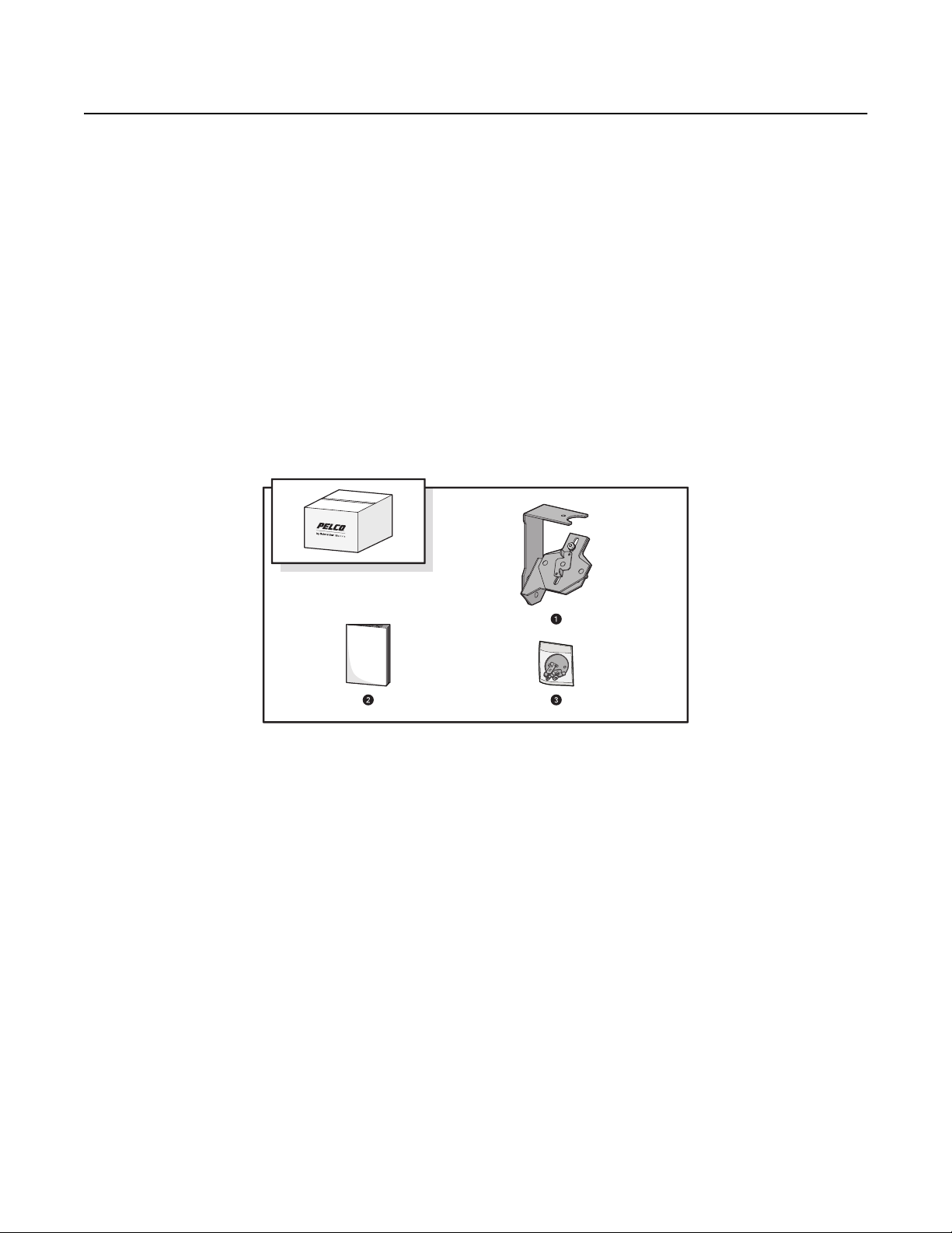
Package Contents
The DF5 adapter kit contains the following items. When installing the adapter kit, refer to this diagram and information.
Figure 1. Package Contents
DF5 Series Adapter
(all parts are factory-assembled)
1 L-swivel bracket
1 Camera base bracket 1 Baseplate wing nut retainer, (DF5-PG-pendant mount only)
1 Slide bracket 1 Spacer baseplate (DF5-in-ceiling mount only)
1 Nut hex, 10-32 SS 1 Spacer baseplate wing stud, 1/4-20 x 1.00-inch (in-ceiling mount only)
1 Split lock washer, #10 SS 1 Flat washer, 1/4-inch SS
1 Flat washer, #10 SS 1 Split lock washer, 1/4-inch SS
1 Tilt angle wing nut retainer
1 Camera wing stud, 1/4-20 x 0.625-inch
2 Split lock washer, 1/4-inch SS
2 Flat washer, 1/4-inch SS
1 Hex finish nut, 1/4-20 SS
4 C3485M-A (5/14)
Installation Manual
Hardware Kit (not all parts are used for all installations)
Page 5
Installing the Adapter Kit
ADAPTER KIT AND DOME COMPATIBILITY
The following DF5 Series domes are compatible with the DF5-BKT Camera Adapter kit.*
DF5-0 DF5-PB-0 DF5-PG-1 DF5-PG-E1
DF5-1 DF5-PB-1 DF5HD-PG-1 DF5HD-PG-E1
DF5HD-1 DF5-PG-0 DF5-PG-E0
*Not for use with DF5-0F, DF5S-0, and DF5S-1 models.
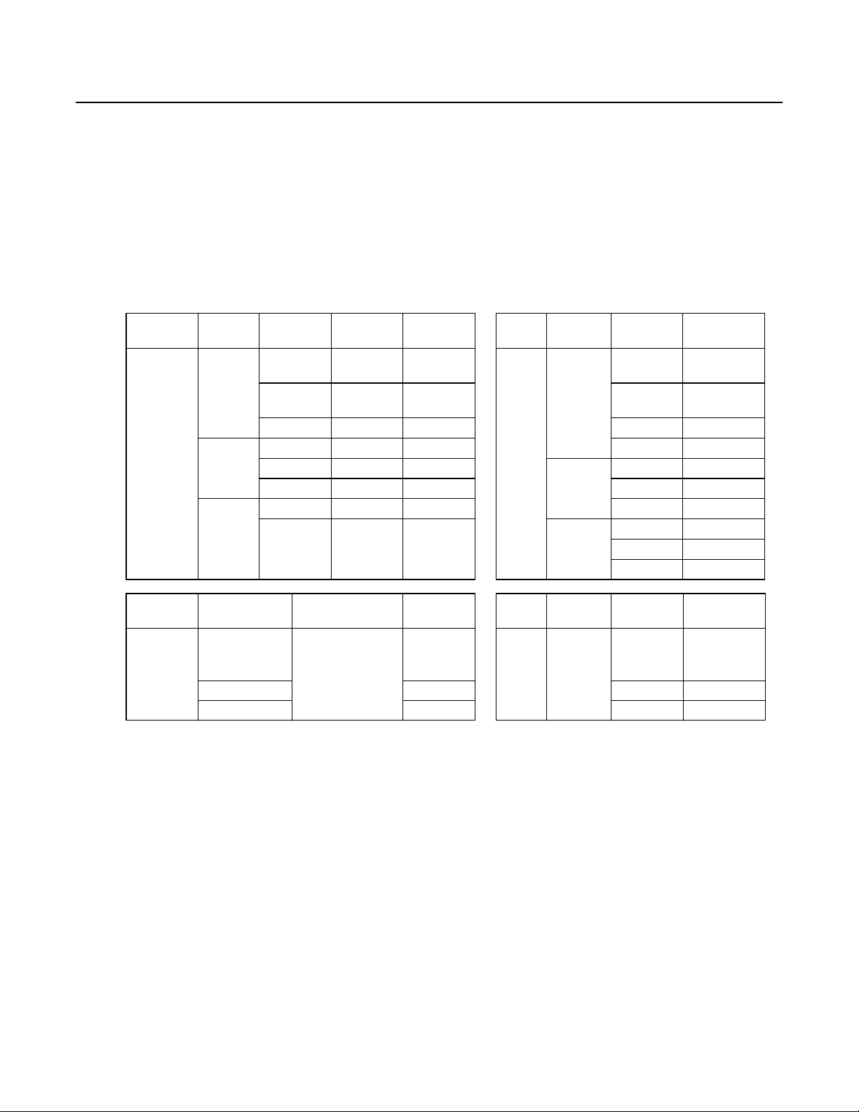
CAMERA AND LENS COMPATIBILITY
Camera models in the tables on the left are compatible with the lens models in the tables on the right for each of the respective groups below.
Camera
Description
1/3-Inch CCD
High
Resolution
Camera
Description
Sarix®SVGA
0.5 MPx
Network
Camera
Type
Day/Night
WDR
Day/Night
Color Box
Camera Type
Low-Light
Day/Night
WDR SureVision
Color IXS0C 2.8 ~ 12 mm 13VD2.8-12
Day/Night IXS0DN 5 ~ 50 mm 13VD5-50
Camera
Power Input
24 VAC or
12 VDC
24 VAC or
12 VDC
220 VAC PAL C20-DW-7X 3~8mm 13VA3-8
24 VAC or
220 VAC PAL C20-DN-7X
24 VAC or
24 VAC or
220 VAC PAL C20-CH-7X
Camera
Format
NTSC C20-DW-6
PAL C20-DW-6X 2.8 ~ 12 mm 13VA2.8-12
PAL C20-DN-6X 5 ~ 50 mm 13VA5-50
NTSC C20-CH-6 2.8 ~ 12 mm 13VD2.8-12
PAL C20-CH-6X 5 ~ 50 mm 13VD5-50
Camera Power
Input
22 to 34 VAC; 24 VAC
nominal or PoE
(IEEE 802.3af class 3)
Camera
Model
Camera
Model
IXS0LW
Lens
Type
Varifocal
Lens
Type
Varifocal Auto
Iris
Manual
Auto
IR
Corrected,
Auto
Iris
Lens Focal
Length
1~3mm 13VA1-3
2.5~6mm 13VD2.5-6
2.8 ~ 11 mm 13VDIR2.8-11
3 ~ 8.5 mm 13VDIR3-8.5
2.8 ~ 11 mm 13VDIR7.5-50
Lens Focal
Length
2.5~6mm 13VD2.5-6
Lens Model
Lens Model
C3485M-A (5/14) 5
Page 6

Camera
Description
Sarix 1.2 MPx
Network With
SureVision
Low-Light
Day/Night
WDR
Sarix 1.3 MPx
Network
Day/Night
Extended
Platform
Sarix 2.1 MPx
Network
Day/Night
Extended
Platform
Sarix 3.1 MPx
Network
Day/Night
Camera Type
Built-in Pelco Analytics
Camera
Power Input
Camera
Model
IXE10LW
Lens Type Iris
Lens Focal
Length
Lens Model
Built-in OV Security Suite IXE10LW-OS
Built-in OV Security Suite
Plus
Built-in OV Event Counting
Suite
IXE10LW-OSP
IXE10LW-OCP
2.2 ~ 6.0 mm 13M2.2-6
Built-in Pelco analytics IXE10DN
Built-in OV Security Suite IXE10DN-OS
Built-in OV Security Suite
Plus
Built-in OV Event Counting
Suite
Built-in Pelco Analytics IXE20DN
22 to 34 VAC;
24 VAC
nominal or PoE
(IEEE 802.3af
class 3)
IXE10DN-OSP
IXE10DN-OCP
Megapixel
Lens,
Varifocal
2.8 ~ 8.0 mm 13M2.8-8
Auto
Built-in OV Security Suite IXE20DN-OS
Built-in OV Security Suite
Plus
Built-in OV Event Counting
Suite
IXE20DN-OSP
IXE20DN-OCP
2.8 ~ 12 mm 13M2.8-12
High Definition Digital IX30DN 15 ~ 50 mm 13M15-50
6 C3485M-A (5/14)
Page 7

PENDANT MOUNT BACK BOX
1. Remove the lower dome assembly from the back box. If necessary, refer to the installation manual that was provided with your DF5 series
equipment for specific installation instructions.
a. Locate one of the two small indentations along the trim ring between the Pelco logo and the ceiling tile. The bubble and trim ring fit
together as one piece called the lower dome, and they are removed as one piece.
b. Use a small flat head screwdriver and gently pry the lower dome away from the back box.
c. Remove the end of the trim ring leash from behind the raised sheet metal stop. Set aside the dome for re-installation later.
2. Remove the old camera and mounting assembly from inside the back box. Be sure you do not remove the baseplate from the back box.
NOTES:
• You will not use the spacer baseplate or the spacer baseplate wing stud included in this kit. They are included for use in the in-ceiling
mount installation only.
• The mounting assembly and camera should be disposed of according to environmental standards in your area.
Figure 2. Adjust The Tilt Angle
L-Swivel Bracket Slide Bracket
Tilt Angle Wing Nut Camera Wing Stud
Camera Base Bracket
3. Adjust the camera base bracket using the tilt angle wing nut until it is in the full upright position.
NOTE: Do not disassemble the adapter assembly as it is ready for installation into the back box.
C3485M-A (5/14) 7
Page 8

4. Insert the L-swivel bracket into the baseplate bolt.
Figure 3. Installing the Adapter: Pendant Mount Back Box
Pendant Mount Back Box Baseplate Wing Nut
Baseplate L-Swivel Bracket
Baseplate Bolt Slide Bracket
Flat Washer Camera Base Bracket
Split Washer Hex Finish Nut (discard)
5. Place the split washer, flat washer, and baseplate wing nut on the baseplate bolt, and partially tighten the wing nut. You will want to keep
the wing nut slightly loose so you can adjust the pan angle later.
6. Proceed to the camera installation instructions.
IN-CEILING MOUNT BACK BOX
Refer to Figure 2 and Figure 4 on page 9 to perform the following steps:
1. Remove the lower dome assembly from the back box.
a. Locate one of the two small indentations along the trim ring between the Pelco logo and the ceiling tile. The bubble and trim ring fit
together as one piece called the lower dome, and they are removed as one piece.
b. Use a small flat head screwdriver and gently pry the lower dome away from the back box.
c. Gently pry the clip on the end of the trim ring leash from the hole on the lip of the back box. Set aside the dome for reinstallation later.
2. Remove the existing camera and mounting assembly from inside the housing. The mounting assembly and camera should be disposed of
according to the environmental standards in your area.
3. Adjust the camera base bracket using the tilt angle wing nut until it is in the full upright position (refer to Figure 2).
NOTE: Do not disassemble the adapter assembly as it is ready for installation into the back box.
4. Align the center holes of the baseplate, the back box, and the L-swivel bracket.
5. Place the split washer and flat washer on the spacer baseplate wing stud, insert the spacer baseplate wing stud through the aligned parts,
and then partially tighten the wing stud. You will want to keep the wing stud slightly loose so you can adjust the pan angle later.
NOTE: You will not use the baseplate wing nut included in this kit; it is included for use in the pendant mount installation only.
8 C3485M-A (5/14)
Page 9

6. Position the adapter assembly within the back box for easier assembly.
a. Identify the two parallel flat sides on the back box, and rotate the L-swivel bracket so that the vertical reach of the L-swivel bracket is
aligned parallel with the two parallel flat sides.
b. Tighten the spacer baseplate wing stud.
7. Proceed to the camera installation instructions.
Figure 4. Installing the Adapter: In-Ceiling Mount Back Box
In-Ceiling Mount Back Box Slide Bracket
Spacer Baseplate Hex Finish Nut (discard)
L-Swivel Bracket Split Washer
Spacer Baseplate Wing Stud Flat Washer
Camera Base Bracket
C3485M-A (5/14) 9
Page 10

Installing the Camera
SARIX IX SERIES
1. Prepare your camera for installation.
a. Locate the center hole and the four holes with rubber plugs located on the top of your camera.
b. Remove the two rubber plugs closest to the top front of the camera using a small flat head screwdriver to pry the rubber plugs from
the mounting holes and discard the rubber plugs.
c. Remove the plastic bracket from the back of the camera.
NOTES:
• Do not remove the two plugs toward the top rear of the camera.
• You will not be able to successfully install your camera without removing the plastic bracket.
d. Install the lens onto the camera and connect the lens cable to the camera.
e. Connect the ethernet cable to the camera. Connect all other cables your installation requires.
Figure 5. Preparing the Camera for Installation
Mounting Holes
Plastic Bracket
10 C3485M-A (5/14)
Page 11

2. Install the camera onto the adapter.
a. Locate the two pegs on the slide bracket and the camera wing stud that is installed between the pegs.
b. Remove and dispose of the hex finished nut on the end of the camera wing stud.
c. Insert the camera wing stud through the single hole in the slide bracket. Do not insert the wing stud through the slot on the slide
bracket; it is provided for use with a different camera installation.
d. Install the camera onto the pegs.
e. Insert the camera wing stud into the center hole, and then partially tighten the camera wing stud. You will want to keep the wing stud
slightly loose so you can adjust the camera depth later.
f. Proceed to the pan, tilt, and depth adjustment instructions.
Figure 6. Installing the Sarix IX Series Camera
L-Swivel Bracket Slide Bracket
Baseplate Wing Nut or Spacer Baseplate Wing Stud Flat Washer
Sarix Camera Split Washer
Camera Base Bracket Camera Wing Stud
Pegs
C3485M-A (5/14) 11
Page 12

C20 SERIES
Refer to Figure 7 to perform the following steps:
1. Prepare the camera for installation.
a. Install the lens onto the camera and connect the lens cable to the camera.
b. Connect the power and data cables to the camera.
2. Install the camera onto the adapter.
a. Locate the two pegs on the slide bracket and the camera wing stud that is installed between the pegs.
b. Remove and dispose of the hex finished nut on the end of the camera wing stud.
c. Insert the camera wing stud through the slot in the slide bracket. Do not insert the wing stud through the single hole in the slide
d. Locate the center hole on the top of your C20 camera.
e. Install the camera between the pegs on the slide bracket, insert the camera wing stud through the slot on the slide bracket and the
f. Proceed to the pan, tilt, and depth adjustment instructions.
bracket; it is provided for use with a different camera installation.
slot on the camera base bracket, and then partially tighten the camera wing stud. You will want to keep the wing stud slightly loose
so you can adjust the camera depth later.
Figure 7. Installing the C20 Series Camera
L- Swivel Bracket Slide Bracket
Baseplate Wing Nut or Spacer Baseplate Wing Stud Flat Washer
Pegs Split Washer
Camera Base Bracket Camera Wing Stud
C20 Series Camera
12 C3485M-A (5/14)
Page 13

Adjusting the Camera
Adjustments to the pan angle, tilt angle, and camera depth are made after the adapter kit and camera are installed. You will use the video
monitor, a handheld monitor, or a mobile device to make these adjustments. Refer to Figure 3 on page 8, Figure 2 on page 7, and Figure 4 on
page 9 to perform the following steps.
PAN ADJUSTMENT
PENDANT MOUNT BACK BOX
1. Loosen the baseplate wing nut slightly, and then turn the adapter kit and camera assembly to the desired pan angle.
2. Tighten the baseplate wing nut once you have the desired pan angle.
3. Proceed to the tilt adjustment.
IN-CEILING BACK BOX INSTALLED WITH THE ORIGINAL SPRING CLIPS
1. Loosen the screws on the back box ring, and then gently push the back box into the ceiling.
2. Turn the back box to the desired pan angle.
3. Tighten the screws to firmly position the spring clips.
4. Proceed to the tilt adjustment.
IN-CEILING BACK BOX INSTALLED WITH THE COLLAPSIBLE RING
1. Loosen the screws on the back box ring.
2. Turn the back box to the desired pan angle.
3. Tighten the screws.
4. Proceed to the tilt adjustment.
TILT ADJUSTMENT
1. Loosen the tilt angle wing nut.
2. Adjust the camera base bracket to the desired tilt angle.
3. Tighten the tilt angle wing nut.
4. Proceed to the depth adjustment.
DEPTH ADJUSTMENT
1. Loosen the camera wing stud.
2. Adjust the camera depth by sliding the slide bracket into or out of the back box.
NOTE: If you have a longer lens, you will need to slide the camera and slide bracket farther into the back box than you would if you have a
shorter lens. You might find it helpful to use the lower dome as a reference as you make this adjustment.
3. Tighten the camera wing stud.
C3485M-A (5/14) 13
Page 14

Testing the Image Quality and Reinstalling the Lower Dome
Once you have completed the pan, tilt, and depth adjustments, you need to test the image quality before you reinstall the lower dome.
NOTES:
• If your C20 camera lens is touching the bubble, you will not be able to reinstall the lower dome. To correct this issue, re-adjust the
camera depth by loosening the camera wing stud, and then push the camera and the slide bracket deeper into the back box.
• If you are installing a Sarix camera and your camera will not install correctly after you have adjusted the camera depth, make sure you
have removed the plastic bracket from the back of the camera.
PENDANT MOUNT
1. Test the image quality of the camera before you install the lower dome. The image should be clear.
2. Reinstall the lower dome.
a. Locate the trim ring leash on the back box and the two raised retainer screws on the lower dome.
b. Slide the hole in the end of the trim ring leash over one of the raised retainer screws.
c. Tuck the end of the trim ring leash behind the raised sheet metal stop, and make sure the leash supports the lower dome before you
let go of the dome.
d. Align the two notches on the outside edge of the lower dome with the two captive screws on the back box, and then push the lower
dome inside the back box.
e. Tighten the screws to secure the lower dome.
3. Retest the image quality after installing the lower dome. If the image is blurry after you have reinstalled the lower dome, contact Pelco
Product Support for more information.
IN-CEILING MOUNT
1. Test the image quality of the camera before you install the lower dome. The image should be clear.
2. Install the lower dome.
a. Snap the clip on the end of the trim ring leash onto the hole on the lip of the back box.
b. Align the snaps on the trim ring with the mounting screws on the back box.
c. Snap the trim ring onto the plastic snap washers on the mounting screws.
3. Retest the image quality after installing the lower dome. If the image is blurry after you have reinstalled the lower dome, contact Pelco
Product Support.
14 C3485M-A (5/14)
Page 15

WARRANTY STATEMENT
For information about Pelco’s product warranty and thereto related information, refer to www.pelco.com/warranty.
This equipment contains electrical or electronic components that must be recycled properly to comply with Directive 2002/96/EC of the European Union
regarding the disposal of waste electrical and electronic equipment (WEEE). Contact your local dealer for procedures for recycling this equipment.
REVISION HISTORY
Manual # Date Comments
C3485M 2/13 Original version.
C3485M-A 5/14 Added Adapter Kit and Dome, and Camera and Lens compatibility tables.
Pelco, the Pelco logo, and other trademarks associated with Pelco products referred to in this publication are trademarks of Pelco, Inc. or its affiliates. ©Copyright 2014,Pelco, Inc.
ONVIF and the ONVIF logo are trademarks of ONVIF Inc. All other product names and services are the property of their respective companies. All rights reserved.
Product specifications and availability are subject to change without notice.
Page 16

Pelco by Schneider Electric 3500 Pelco Way Clovis, California 93612-5699 United States
USA & Canada Tel (800) 289-9100 Fax (800) 289-9150
International Tel +1 (559) 292-1981 Fax +1 (559) 348-1120
www.pelco.com www.pelco.com/community
 Loading...