

Page 1
OPERATION/PROGRAMMING
®
Spectra III™ Series
DD53CBW18 & DD53CBW18-X
C2487M-B (11/05)
Page 2

Page 3

OPERATION/PROGRAMMING MANUAL
MODELS DD53CBW18 & DD53CBW18-X
18X DAY/NIGHT CAMERA
Page 4

4 C2487M-B (11/05)
Page 5

CONTENTS
WELCOME ................................................................................................................................................................................................. 7
GETTING STARTED ........................................................................................................................................................................... 7
HOW TO OPERATE YOUR DOME SYSTEM ............................................................................................................................................... 8
ACCESSING MAIN MENU (PRESET 95) ........................................................................................................................................... 9
CM6700/CM6800 .................................................................................................................................................................... 9
KBD200A/KBD300A (DIRECT MODE ONLY) ............................................................................................................................ 9
CM9500 ................................................................................................................................................................................... 9
CM9740/CM9760/CM9770/CM9780 ..................................................................................................................................... 9
KBD4000/KBD4002 ............................................................................................................................................................... 10
MPT9500 ............................................................................................................................................................................... 10
NET300/NET350/NET4001A ................................................................................................................................................. 10
WS5050 ................................................................................................................................................................................. 10
VCD5000 ................................................................................................................................................................................ 10
QUICK START GUIDE – SYSTEM SETUP ................................................................................................................................................. 11
LANGUAGE .............................................................................................................................................................................................. 13
SYSTEM INFORMATION.......................................................................................................................................................................... 14
DISPLAY SETUP ....................................................................................................................................................................................... 15
LABEL POSITION ............................................................................................................................................................................. 16
DOME SETTINGS ..................................................................................................................................................................................... 17
CAMERA ......................................................................................................................................................................................... 17
AUTO FOCUS ......................................................................................................................................................................... 17
ZOOM LIMIT .......................................................................................................................................................................... 18
ZOOM SPEED ......................................................................................................................................................................... 18
LOW LIGHT LIMIT .................................................................................................................................................................. 18
IR CUT FILTER ......................................................................................................................................................................... 19
ADVANCED CAMERA SETTINGS ................................................................................................................................................... 20
SHUTTER SPEED .................................................................................................................................................................... 20
AGC LIMIT ............................................................................................................................................................................. 20
AUTO IRIS .............................................................................................................................................................................. 21
AUTO SHARPNESS ................................................................................................................................................................ 22
AUTO WHITE BALANCE ........................................................................................................................................................ 22
BACKLIGHT COMPENSATION (BLC) ...................................................................................................................................... 23
VIDEO LEVEL .......................................................................................................................................................................... 24
MOTION SETTINGS ........................................................................................................................................................................ 25
AUTO FLIP .............................................................................................................................................................................. 25
PROPORTIONAL PAN ............................................................................................................................................................. 25
PARK TIME ............................................................................................................................................................................ 26
SCAN SPEED ......................................................................................................................................................................... 27
PRESET FREEZE FRAME ........................................................................................................................................................ 27
LIMIT STOPS .......................................................................................................................................................................... 28
AZIMUTH ZERO ..................................................................................................................................................................... 29
POWER UP ...................................................................................................................................................................................... 30
POWER UP ACTION ............................................................................................................................................................... 30
C2487M-B (11/05) 5
Page 6

LINE SYNC ...................................................................................................................................................................................... 31
PRESETS ......................................................................................................................................................................................... 32
PATTERNS....................................................................................................................................................................................... 34
ZONES ............................................................................................................................................................................................ 35
WINDOW BLANKING ..................................................................................................................................................................... 36
REVERSE ................................................................................................................................................................................ 38
CLEAR WINDOW ................................................................................................................................................................... 38
BLANK ALL ABOVE/BLANK ALL BELOW ............................................................................................................................... 38
ALARMS ......................................................................................................................................................................................... 39
AUX ................................................................................................................................................................................................. 40
TITLE TEXT ...................................................................................................................................................................................... 41
ALERT ............................................................................................................................................................................................. 42
REPEAT................................................................................................................................................................................... 42
ACK ACTION .......................................................................................................................................................................... 43
ACTIVATE AUX ....................................................................................................................................................................... 43
CURRENT READING .............................................................................................................................................................. 43
ALERT RESET ......................................................................................................................................................................... 43
CLEAR ............................................................................................................................................................................................. 44
PASSWORD .................................................................................................................................................................................... 45
RESET, CYCLE POWER, REBOOT ............................................................................................................................................................. 46
RESET CAMERA .................................................................................................................................................................... 46
CYCLE CAMERA POWER ....................................................................................................................................................... 46
REBOOT SYSTEM .................................................................................................................................................................. 46
SOFTWARE/LANGUAGE FILE UPLOAD ................................................................................................................................................... 47
UPLOAD ICON ................................................................................................................................................................................. 47
SPECIFICATIONS...................................................................................................................................................................................... 48
DD53CBW18 .......................................................................................................................................................................... 48
DD53CBW18-X ...................................................................................................................................................................... 48
REGULATORY NOTICES ........................................................................................................................................................................... 49
6 C2487M-B (11/05)
Page 7

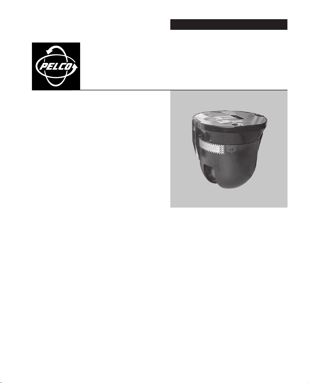
WELCOME
Thank you for purchasing Pelco’s premier integrated dome system, Spectra III. Your new system
features a high resolution, day/night camera/optics package with IR filter and programmable
dome drive software.
This manual is designed to be a reference tool for the operation and programming of your
system. Inside you will find information about Spectra III’s features and commands, as well as a
detailed menu tree.
Getting Started
You will need to install your dome system before using this manual. Refer to the installation
packet supplied with the back box for installation instructions.
Once installed apply power to the Spectra III dome system. The system will start a configuration
sequence. When configuration is done, the following information is displayed:
Pelco Spectra III
Version X.XX*
D Address: 1
P Address: 2
Comm 2400, N, 8, 1
CONFIGURE DONE
This information will remain on the monitor until dome operation begins.
Refer to the following pages to learn how to operate and program your dome system.
*Pressurized Spectra III dome systems require software version 1.27 or higher to monitor
temperature, pressure, and dew point.
C2487M-B (11/05) 7
Page 8

HOW TO OPERATE YOUR DOME SYSTEM
Operation How to Control
Pan and Tilt Move joystick or press the direction keys left/right and up/down.
Zoom Far To zoom far, do the following:
1. Press the Zoom Tele button or turn the joystick clockwise until zoom stops at the 32X zoom limit.
2. Release the button or joystick for one second.
3. To continue zooming (digitally), press the button or turn the joystick clockwise again until you have the
picture you want or reach the digital zoom1 limit.
Zoom Wide Press the Zoom Wide button or turn the joystick counterclockwise.
Scanning
Stop Scan Preset 96
Random Scan Preset 97
Frame Scan Preset 98
Auto Scan Preset 99
Presets Refer to the documentation supplied with the control system.
Patterns
2
Refer to the documentation supplied with the control system.
Zones Refer to the
Auto Flip Turn on or off in the programming menu. Refer to the
1
Digital zoom magnifies the image electronically and the picture may appear pixilated. The larger the digital zoom limit the
Zones
section and to the documentation supplied with the control system.
Auto Flip
section in this manual.
greater the reduction in resolution.
2
The dome cannot do digital zoom in a pattern. Optical zoom will operate in a pattern.
8 C2487M-B (11/05)
Page 9

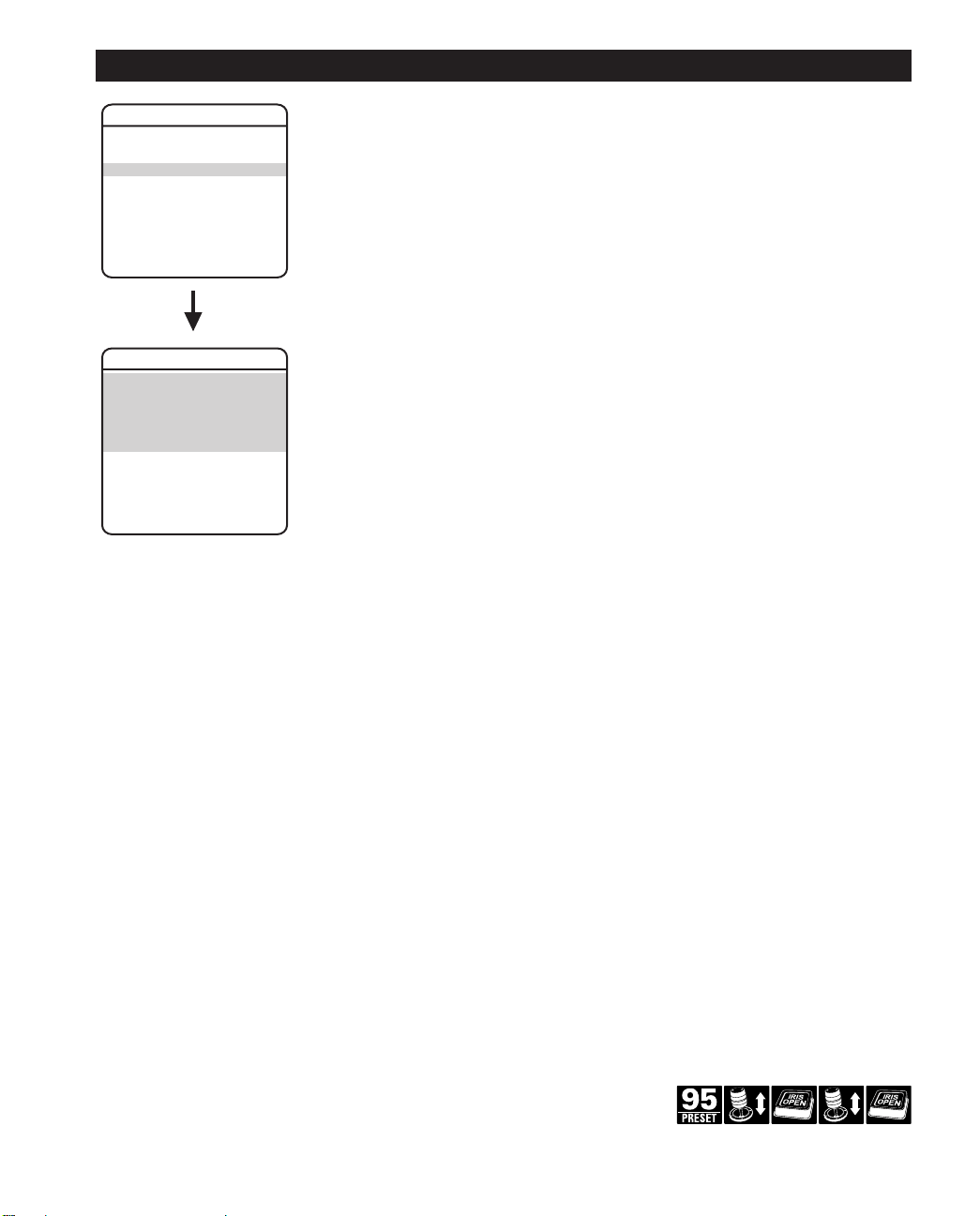
Accessing Main Menu (Preset 95)
You can call up the main menu on your monitor by programming (setting or creating) preset 95
(preset 28 if in AD32-preset mode).
Programming preset 95 for Pelco’s controllers varies according to the type of controller you are
using. Instructions for programming preset 95 are given below for various Pelco controllers.
CM6700/CM6800
1. Enter the number of the Spectra dome system and press the CAM key.
2. Enter 95 and hold the PRESET key for two seconds.
3. In the Edit Preset menu, arrow to SET and press the ACK key. The main menu appears.
KBD200A/KBD300A (Direct Mode Only)
1. Enter 95.
2. Hold the PRESET key (approximately five seconds) until the main menu appears on the
screen.
CM9500
1. Enter the number of the Spectra dome system and press the CAM key. The Main menu
appears.
2. Highlight SETUP in the Main menu and press the SELECT key.
3. Highlight CAM in the Setup menu and press the SELECT key.
4. Highlight PRESET in the Camera menu and press the SELECT key.
5. Enter 95 and press the F1 key. The main menu appears.
CM9740/CM9760/CM9770/CM9780
1. Press the ESCAPE key to open the Main menu. Select DEF. The Define Submenu appears.
2. Enter your four-digit PIN
3. Enter 95 and select PRST. The main menu appears on the monitor.
4. Select the Quit icon to return to the default menu.
C2487M-B (11/05) 9
if this is your first time entering this mode.
(Continued on next page)
Page 10

KBD4000/KBD4002
1. Press the SPOT MONITOR key.
2. Enter 95, then hold the PRESET key (approximately five seconds) until the main menu
appears on the screen.
MPT9500
Standard Coaxitron Mode
1. Enter 95 and press the PRESET SET key.
2. Position the asterisk in the YES row and press the F1 key. The main menu appears.
Extended Coaxitron or RS-485 Mode
1. Enter 95 and press the PRESET SET key.
2. Press the F2 key. The main menu appears.
NET300/NET350/NET4001A
1. Check the Set box.
2. Click the preset 95 button. The main menu appears.
WS5050
1. Right-click in the video pane of the Spectra dome system.
2. Click Preset and then click Select Preset.
3. Enter 95 and then click OK.
VCD5000
1. Enter 95 for the preset action. The shortcut menu appears.
2. Press the Preset button on the KBD5000.
10 C2487M-B (11/05)
Page 11
SPECTRA III
LANGUAGE ENGLISH
<SYSTEM INFORMATION>
<DISPLAY SETUP>
<DOME SETTINGS>
ACK ALERT**
EXIT
RESET CAMERA
CYCLE CAMERA POWER
REBOOT SYSTEM
DOME SETTINGS
<CAMERA>
<MOTION>
<POWER UP>
<LINE SYNC>
<PRESETS>
<PATTERNS>
<ZONES>
<WINDOW BLANKING>
<ALARMS>
<AUX>
<TITLE TEXT>
<ALERT>**
<CLEAR>
<PASSWORD>
BACK
EXIT
PRESET NUMBER 1
* * * PRESET NOT DEFINED * * *
POWER UP ACTION
BACK
EXIT
AUTO FLIP
PROPORTIONAL PAN
PARK TIME (MINUTES)
PARK ACTION
SCAN SPEED DEG/S
PRESET FREEZE FRAME
CAMERA
AUTO FOCUS
ZOOM LIMIT
BACK
EXIT
DISPLAY SETUP
PRESET LABEL 2 (SECS)
ZONE LABEL 2 (SECS)
ZOOM 2 (SECS)
AZIMUTH/ELEVATION 2 (SECS)
DIRECTION OFF
ALARM MESSAGE 2 (SECS)
<LABEL POSTIONS>
RESTORE FACTORY DEFAULTS
BACK
EXIT
FREE MEMORY
LAST RESET
AZIMUTH ZERO OFFSET
MOTOR ACTIVE
CAMERA ACTIVE
FPGA VERSION X
VIDEO LEVEL NORMAL
CAMERA XXXX-XXXX
BACK
EXIT
18304
POWER ON
0
O
YES
YES
DOME DRIVE MODEL
BACK BOX MEMORY
SOFTWARE VERSION
BIOS VERSION
FONT VERSION
COMM
D ADDRESS
P ADDRESS
CM9500 MODE
32 PRESETS
PROTOCOL
DD53CBW18
AVAILABLE
XX.X
XX.X
XX.X
2400, N, 8, 1
1
2
OFF
OFF
C
SYSTEM INFORMATION
<ADDITIONAL>
BACK
EXIT
<SET AZIMUTH ZERO>
<CLEAR AZIMUTH ZERO>
LIMIT STOPS
<SET MANUAL STOPS>
<CLEAR MANUAL STOPS>
<SET SCAN STOPS>
<CLEAR SCAN STOPS>
LINE SYNC ON
LINE SYNC PHASE 0
BACK
EXIT
ZONE NUMBER 1
* * * ZONE NOT DEFINED * * *
<EDIT ZONE LABEL>
<EDIT ZONE>
ZONE ENABLED
ZONE BLANKING
<CLEAR ZONE>
BACK
EXIT
PATTERN NUMBER 1
<PROGRAM PATTERN>
<CLEAR PATTERN>
BACK
EXIT
REFERENCE INFORMATION
PATTERN USAGE
REMAINING
<SET WINDOW>
STYLE GRAY
BLANK ALL ABOVE OFF
BLANK ALL BELOW OFF
BACK
EXIT
ALARM CONTACT N/O
BACK
EXIT
AUX 1 MODE
DWELL TIME (SECS)
AUX 2 MODE
DWELL TIME (SECS)
BACK
EXIT
RESTORE FACTORY DEFAULTS
BACK
EXIT
ENABLE PASSWORD OFF
<EDIT PASSWORD>
BACK
EXIT
ADVANCED SETTINGS
WINDOW NUMBER 1
<EDIT WINDOW LOCATION>
<EDIT WINDOW ZOOM>
ENABLE WINDOW NO
REVERSE
CLEAR WINDOW
BACK
EXIT
ADDITIONAL
LANGUAGE 1
LANGUAGE 6
ON
X144
MEDIUM
ZOOM SPEED
LOW LIGHT LIMIT
IR CUT FILTER
AUTO IR LEVEL
<ADVANCED SETTINGS>
DUSK
AUTO
SHUTTER SPEED
AGC LIMIT
AUTO IRIS
AUTO IRIS LEVEL
AUTO IRIS PEAK
AUTO SHARPNESS
SHARPNESS LEVEL
AUTO WHITE BALANCE
R GAIN
B GAIN
BACKLIGHT COMP
VIDEO LEVEL
BACK
EXIT
AUTO
28
AUTO
66
8
ON
26
ON
482
678
OFF
HIGH
ON
ON
0
NONE
25
AUTO
ON
MOTION
BACK
EXIT
POWER UP LINE SYNC
PRESETS
<EDIT PRESET LABEL>
<EDIT PRESET SCENE>
REFERENCE INFORMATION
AZIMUTH
ELEVATION
ZOOM
<CLEAR PRESET>
BACK
EXIT
PATTERNS ZONES WINDOW BLANKING
SET WINDOW
TOGGLE
1
TOGGLE
1
ALARMS*** ALERT**
TEMPERATURE
DEWPOINT
PRESSURE
REFRESH
BACK
EXIT
0°C
0°F
0°C
0°F
0.0 PSIG
0.0 BAR
CURRENT READING**
REPEAT
ACK ACTION
RESET ALERT
BACK
EXIT
CONSTANT
ALWAYS ON
ACTIVATE AUX
<CURRENT READING>
NO
AUX***
ENABLE TITLE TEXT
<EDIT TITLE TEXT>
BACK
EXIT
TITLE TEXT CLEAR PASSWORD
1234567890
ABCDEFGHIJ
KLMNOPQRST
UVWXYZ.,-/
abcdefghij
klmnopqrst
uvwxyz#&:*
OK
CANCEL
SPACE
BACKSPACE
EDIT THE PASSWORD
----------
NO
OFF
ENGLISH X.XX
ITALIANO X.XX
LABEL POSITION
[ZONE LABEL-------]
[PRESET LABEL-------]
[ALARM 1-------]
[ALERT MESSAGE-------]**
[TITLE TEXT]
SAVE AND EXIT
CANCEL AND EXIT
HELP
XXX°/-XX°
NE
XXX.XX
PRESSURIZED**
X.XX
AUTO
100%
0%
-
-
-
Presets
The following presets are reserved for special functions.
Preset Function
33 Flip command
34 Pan zero command
83-87 Reserved
88 IR filter IN (color)
89 IR filter OUT (black-white)
90-91 Manual limit stops
92-93 Scan limit stops
94 Reserved
95 Select main programming menu
96 Stop a scan
97 Random scanning
98 Frame scanning
99 Start auto scanning
NOTE: For American Dynamics controllers with only 32 presets, switch
SW3-1 on the dome drive to the ON position. When SW3-1 is ON, preset
99 becomes 32 92 becomes 25
98 becomes 31 91 becomes 24
97 becomes 30 90 becomes 23
96 becomes 29 89 becomes 22
95 becomes 28 88 becomes 21
93 becomes 26
If the limit stops are turned off, presets 23-26 can be used as regular
presets.
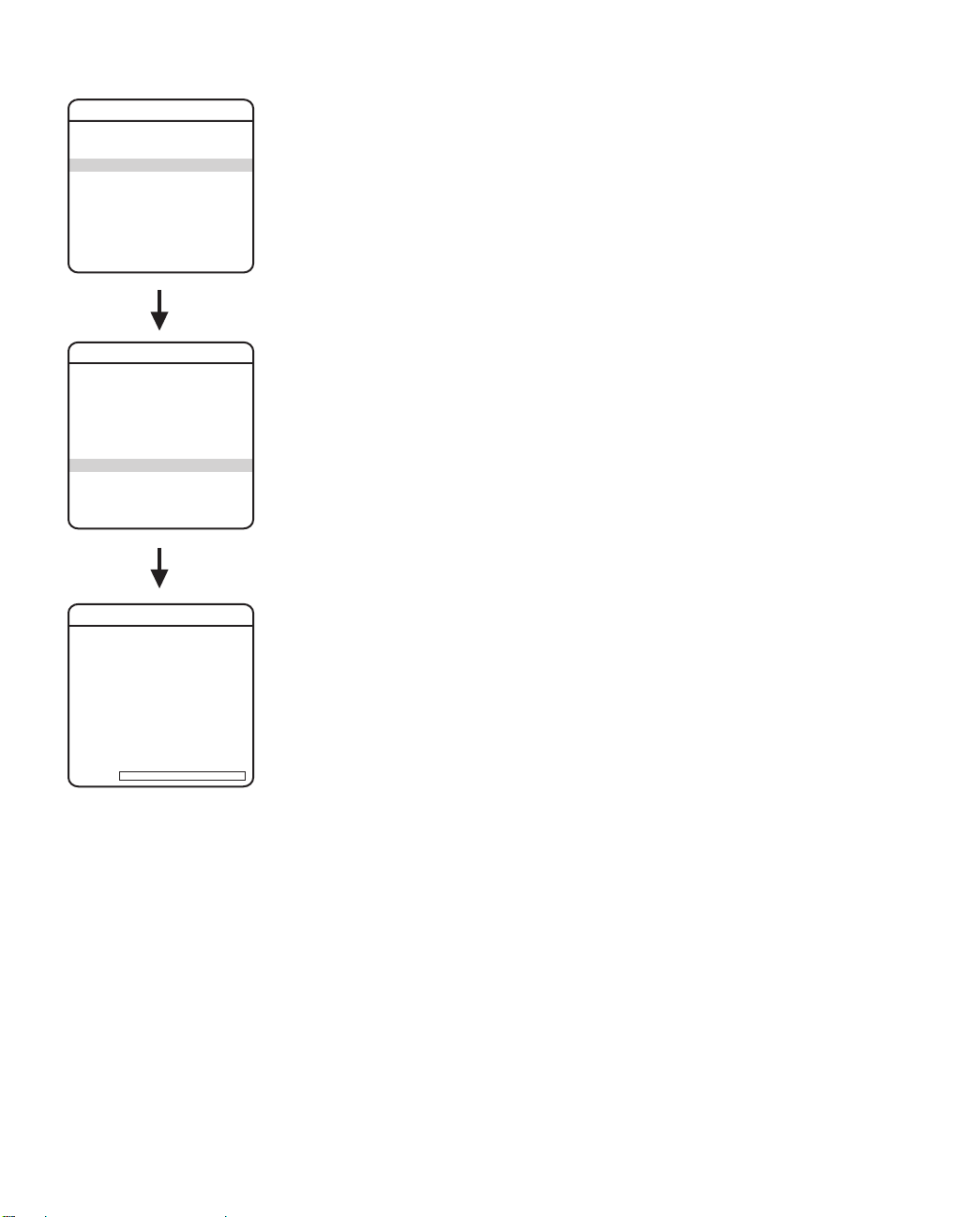
QUICK START GUIDE – SYSTEM SETUP
Quick Programming Guide
Access main menu (preset 95). See the
(Preset 95)
section.
Use the joystick* to position the cursor beside menu selection.
Press Iris Open, the submenu/cursor moves to the right.
Move the joystick up or down to view selections.
Press Iris Open to make selection.
Press Iris Close to cancel selection.
Accessing Main Menu
*** This feature is functional only if the dome drive
is installed in the Spectra III SE back box.
*If your controller does not have a joystick, use the up or down key.
**This setting only applies to Pressurized Spectra III dome systems
with software version 1.27 or higher. Spectra III systems that are
not pressurized or pressurized systems that do not have dome drive
C2487M-B (11/05) 11
software version 1.27 or higher will not display this menu item.
Software version 1.27 or higher includes the software to monitor
temperature, pressure, and dew point for Pressurized Spectra III
systems.
Page 12

Page 13
LANGUAGE
SPECTRA III
LANGUAGE ENGLISH
<SYSTEM INFORMATION>
<DISPLAY SETUP>
<DOME SETTINGS>
ACK ALERT*
RESET CAMERA
CYCLE CAMERA POWER
REBOOT SYSTEM
EXIT
*This setting only applies to
Pressurized Spectra III dome
systems with software version
1.27 or higher.
The language for the on-screen menus is selectable. Available languages include English,
Spanish, French, German, Italian, Portuguese, Russian, Polish, Turkish, and Czechoslovakian.
The factory default language is English.
NOTE: The dome system cannot store all 10 languages in its memory. There are two language
packages available. The standard language package includes English, Spanish, Portuguese,
Italian, French, and German. The alternate package includes English, Russian, Polish, Turkish,
and Czechoslovakian. If your dome system does not have the language package that you require,
you must upload the other language package. Refer to the
Software/Language File Upload
section.
To change the display language:
1. Use the joystick to position the cursor beside LANGUAGE.
2. Press Iris Open. The cursor moves to the right, beside the current, selected language.
3. Move the joystick up or down to view selections. Press Iris Open to enter selection.
All on-screen menus are changed to the selected language.
Quick Programming Guide
(See page 11)
C2487M-B (11/05) 13
Page 14
SYSTEM INFORMATION
SPECTRA III
LANGUAGE ENGLISH
<SYSTEM INFORMATION>
<DISPLAY SETUP>
<DOME SETTINGS>
ACK ALERT*
RESET CAMERA
CYCLE CAMERA POWER
REBOOT SYSTEM
EXIT
SYSTEM INFORMATION
DOME DRIVE MODEL DD53CBW18
BACK BOX MEMORY AVAILABLE
SOFTWARE VERSION XX.X
BIOS VERSION XX.X
FONT VERSION XX.X
COMM 2400, N, 8, 1
D ADDRESS 1
P ADDRESS 2
CM9500 MODE OFF
32 PRESETS OFF
PROTOCOL C
PRESSURIZED* X.XX
<ADDITIONAL>
BACK
EXIT
The system Information screen displays dome drive model, software version, available memory,
and other diagnostic information.
System settings cannot be changed using this screen. This screen is for reference only.
Use the following steps to display the System Information screen:
1. Use the joystick to position the cursor beside SYSTEM INFORMATION.
2. Press Iris Open. The SYSTEM INFORMATION window opens.
FREE MEMORY 18304
LAST RESET POWER ON
AZIMUTH ZERO OFFSET 0
MOTOR ACTIVE YES
CAMERA ACTIVE YES
FPGA VERSION X
VIDEO LEVEL NORMAL
CAMERA XXXX-XXXX
LANGUAGE 1 ENGLISH X.XX
LANGUAGE 2 ESPANOL X.XX
LANGUAGE 3 PORTUGUES X.XX
LANGUAGE 4 DEUTSCH X.XX
LANGUAGE 5 FRANCAIS X.XX
LANGUAGE 6 ITALIANO X.XX
BACK
EXIT
ADDITIONAL
o
*This setting only applies to
Pressurized Spectra III dome
systems with software version
1.27 or higher.
14 C2487M-B (11/05)
Page 15
DISPLAY SETUP
SPECTRA III
LANGUAGE ENGLISH
<SYSTEM INFORMATION>
<DISPLAY SETUP>
<DOME SETTINGS>
ACK ALERT*
RESET CAMERA
CYCLE CAMERA POWER
REBOOT SYSTEM
EXIT
Display setup allows you to program how labels are displayed on the monitor. The following
labels are available:
A preset label is displayed when a preset is called. A zone label is displayed when the system
DISPLAY SETUP
PRESET LABEL 2 (SECS)
ZONE LABEL 2 (SECS)
ZOOM 2 (SECS)
AZIMUTH/ELEVATION 2 (SECS)
DIRECTION OFF
ALARM MESSAGE 2 (SECS)
<LABEL POSITIONS>
RESTORE FACTORY DEFAULTS
BACK
EXIT
*This setting only applies to
Pressurized Spectra III dome
systems with software version
1.27 or higher.
moves into a zone. The zoom label is displayed when zoom is activated. Azimuth/elevation and
direction labels are displayed when pan/tilt is activated. An alarm message appears on the
monitor when a defined preset alarm occurs.
The following settings are available for each label:
1
Azimuth is the pan angle from 0° to 359°.
2
Elevation is the tilt position from 0° (horizon) to -90°.
PRESET LABEL Identifies preset.
ZONE LABEL Identifies zone.
ZOOM Identifies the amount of magnification.
AZIMUTH
1
/ELEVATION2Amount of pan from 0° and the amount of tilt from 0°
horizontal.
DIRECTION Displays compass direction.
ALARM MESSAGE Displays activated alarm.
OFF Label is not displayed when activated.
CONSTANT The label is continually displayed when activated.
2 SECONDS The label is displayed for 2 seconds after activation.
5 SECONDS The label is displayed for 5 seconds after activation.
10 SECONDS The label is displayed for 10 seconds after activation.
Quick Programming Guide
(See page 11)
C2487M-B (11/05) 15
Page 16
Label Position
SPECTRA III
LANGUAGE ENGLISH
<SYSTEM INFORMATION>
<DISPLAY SETUP>
<DOME SETTINGS>
ACK ALERT*
RESET CAMERA
CYCLE CAMERA POWER
REBOOT SYSTEM
EXIT
Labels can be placed anywhere on the monitor. This feature allows you to customize the
appearance of your monitor screen.
The following labels are not set at fixed positions:
PRESET LABEL
ZONE LABEL
ALARM 1
ZOOM RATIO - XXX.XX
AZIMUTH
DIRECTION - NE
DISPLAY SETUP
PRESET LABEL 2 (SECS)
ZONE LABEL 2 (SECS)
ZOOM 2 (SECS)
AZIMUTH/ELEVATION 2 (SECS)
DIRECTION OFF
ALARM MESSAGE 2 (SECS)
<LABEL POSITIONS>
RESTORE FACTORY DEFAULTS
BACK
EXIT
ALERT MESSAGE3*
TITLE TEXT
To set a label position:
1. Use the joystick to position the cursor beside a label.
2. Press Iris Open.
3. Use the joystick to move the label up, down, left, and/or right.
4. Press Iris Open.
5. Repeat steps 1 through 4 to position other labels.
6. Position the cursor next to Save and Exit. Press Iris Open to save settings and exit
1
LABEL POSITION
[ZONE LABEL-------]
[PRESET LABEL-------]
[ALARM 1-------]
[ALERT MESSAGE-------]*
[TITLE TEXT]
SAVE AND EXIT
CANCEL AND EXIT
HELP
XXX°/-XX°
NE
XXX.XX
Azimuth is the pan angle from 0° to 359°.
2
Elevation is the tilt position from 0° (horizon) to -90°.
3
The alert message is the warning displayed on the monitor if pressure, temperature, or dew
point inside the dome reach unacceptable levels.
1
/ELEVATION2 - XXX°/-XX°
menu.
*This setting only applies to
Pressurized Spectra III dome
systems with software version
1.27 or higher.
16 C2487M-B (11/05)
Page 17

DOME SETTINGS
Camera
SPECTRA III
LANGUAGE ENGLISH
<SYSTEM INFORMATION>
<DISPLAY SETUP>
<DOME SETTINGS>
ACK ALERT*
RESET CAMERA
CYCLE CAMERA POWER
REBOOT SYSTEM
EXIT
DOME SETTINGS
<CAMERA>
<MOTION>
<POWER UP>
<LINE SYNC>
<PRESETS>
<PATTERNS>
<ZONES>
<WINDOW BLANKING>
<ALARMS>
<AUX>
<TITLE TEXT>
<ALERT>*
<CLEAR>
<PASSWORD>
BACK
EXIT
AUTO FOCUS
Auto focus allows the lens to remain in focus during zoom-in, zoom-out, and motion functions.
There are two auto focus settings:
ON (default) If auto focus mode is set to ON, the camera will focus automatically when
using pan, tilt, and zoom functions.
OFF Focus is operated manually. To focus, press the Focus Far or Focus Near
button on the controller.
CAMERA
AUTO FOCUS ON
ZOOM LIMIT X144
ZOOM SPEED MEDIUM
LOW LIGHT LIMIT 2
IR CUT FILTER AUTO
AUTO IR LEVEL DUSK
<ADVANCED SETTINGS>
BACK
EXIT
*This setting only applies to
Pressurized Spectra III dome
systems with software version
1.27 or higher.
Quick Programming Guide
(See page 11)
C2487M-B (11/05) 17
Page 18

SPECTRA III
LANGUAGE ENGLISH
<SYSTEM INFORMATION>
<DISPLAY SETUP>
<DOME SETTINGS>
ACK ALERT*
RESET CAMERA
CYCLE CAMERA POWER
REBOOT SYSTEM
EXIT
ZOOM LIMIT
Zoom limit allows the user to define a limitation on the amount of telephoto zoom. The default
setting is 144X.
Cameras with 180X zoom (18X optical zoom and 10X digital zoom) can be set for 18X, 32X, 72X,
144X, or 180X.
ZOOM SPEED
Zoom Speed allows the user to define how fast the dome will go from full wide zoom to the 18X
optical zoom. The default setting is MEDIUM.
DOME SETTINGS
<CAMERA>
<MOTION>
<POWER UP>
<LINE SYNC>
<PRESETS>
<PATTERNS>
<ZONES>
<WINDOW BLANKING>
<ALARMS>
<AUX>
<TITLE TEXT>
<ALERT>*
<CLEAR>
<PASSWORD>
BACK
EXIT
CAMERA
AUTO FOCUS ON
ZOOM LIMIT X144
ZOOM SPEED MEDIUM
LOW LIGHT LIMIT 2
IR CUT FILTER AUTO
AUTO IR LEVEL DUSK
<ADVANCED SETTINGS>
BACK
EXIT
*This setting only applies to
Pressurized Spectra III dome
systems with software version
1.27 or higher.
Available settings for zoom speed include the following:
HIGH 2.9 seconds
MEDIUM (default) 4.2 seconds
LOW 5.8 seconds
NOTE: When using the HIGH setting, the image may be out of focus until zooming stops.
LOW LIGHT LIMIT
Low light limit is the maximum duration, in fractions of a second, that the electronic shutter will
remain open in low light conditions. The default setting is 2.
Settings include the following:
2 = 1/2 second 8 = 1/8 second 30 = 1/30 second
4 = 1/4 second 15 = 1/15 second 60 = 1/60 second
18 C2487M-B (11/05)
Page 19

SPECTRA III
LANGUAGE ENGLISH
<SYSTEM INFORMATION>
<DISPLAY SETUP>
<DOME SETTINGS>
ACK ALERT*
RESET CAMERA
CYCLE CAMERA POWER
REBOOT SYSTEM
EXIT
DOME SETTINGS
<CAMERA>
<MOTION>
<POWER UP>
<LINE SYNC>
<PRESETS>
<PATTERNS>
<ZONES>
<WINDOW BLANKING>
<ALARMS>
<AUX>
<TITLE TEXT>
<ALERT>*
<CLEAR>
<PASSWORD>
BACK
EXIT
IR CUT FILTER
Spectra III has two modes of operation: color, and black and white. You can increase sensitivity
in low light conditions by switching to black and white mode (removing the IR cut filter). Color
mode is preferred in normal lighting conditions.
The following are the settings for the IR cut filter:
OFF Manual operation is controlled by preset 88 (filter IN) and 89
(filter OUT).
AUTO (default) Automatic operation is controlled by the Auto IR Level setting.
Auto IR Level
The auto IR level is the light level at which the infrared filter switches IN or OUT.
Following are the available settings for the Auto IR Level:
DUSK (default) approximately 6 lux (black-white)
approximately 13 lux (color)
DARK approximately 0.1 lux (black-white)
approximately 2 lux (color)
NOTE: If backlight compensation is ON and the IR cut filter switches OUT in normal lighting
conditions, adjust the Auto IR Level to a darker setting. Refer to the
section.
NOTE: LOW LIGHT does not mean NO LIGHT. Some type of illumination is required (street light,
IR light, etc.). The camera is not sensitive to IR light when the IR cut filter is IN.
Backlight Compensation
CAMERA
AUTO FOCUS ON
ZOOM LIMIT X144
ZOOM SPEED MEDIUM
LOW LIGHT LIMIT 2
IR CUT FILTER AUTO
AUTO IR LEVEL DUSK
<ADVANCED SETTINGS>
BACK
EXIT
*This setting only applies to
Pressurized Spectra III dome
systems with software version
1.27 or higher.
Quick Programming Guide
(See page 11)
C2487M-B (11/05) 19
Page 20

Advanced Camera Settings
SPECTRA III
LANGUAGE ENGLISH
<SYSTEM INFORMATION>
<DISPLAY SETUP>
<DOME SETTINGS>
ACK ALERT*
RESET CAMERA
CYCLE CAMERA POWER
REBOOT SYSTEM
EXIT
DOME SETTINGS
<CAMERA>
<MOTION>
<POWER UP>
<LINE SYNC>
<PRESETS>
<PATTERNS>
<ZONES>
<WINDOW BLANKING>
<ALARMS>
<AUX>
<TITLE TEXT>
<ALERT>*
<CLEAR>
<PASSWORD>
BACK
EXIT
CAMERA
AUTO FOCUS ON
ZOOM LIMIT X144
ZOOM SPEED MEDIUM
LOW LIGHT LIMIT 2
IR CUT FILTER AUTO
AUTO IR LEVEL DUSK
<ADVANCED SETTINGS>
SHUTTER SPEED
Shutter speed is the duration of the electronic shutter. Program shutter speed to operate
automatically (Auto) or manually (Numeric Value).
AUTO (default) The electronic shutter speed is set automatically by the amount of
light sensed by the camera.
NUMERIC VALUE Spectra III SE dome system has several numerical shutter speed
settings. The higher the number, the faster the electronic shutter.
The slowest shutter speed setting is 2 = 1/2 second
The fastest setting is 30,000 = 1/30,000 second
Increasing the shutter speed lowers the light sensitivity and
reduces the streaking of fast moving objects.
NOTE: Set the shutter speed to 100 if you are using an NTSC camera in a 50 Hz environment.
This will eliminate any flicker that may occur in the picture.
AGC LIMIT
AGC Limit allows users to adjust how the system balances AGC (automatic gain control) and
electronic shutter in low light conditions. As scene lighting decreases, the system will
automatically adjust, adding a mixture of AGC and slow shutter according to the AGC LIMIT
setting. AGC LIMIT can be set between 0 and 40, with 40 applying maximum AGC before slow
shutter. In contrast, setting AGC LIMIT to 0 will force the system software to apply maximum
slow shutter (as defined by the LOW LIGHT LIMIT setting) before any AGC is applied. The default
setting of 28 sets the AGC and slow shutter balance to favor AGC, yielding more real-time low
light images.
NOTE: The maximum slow shutter that the system will achieve is 1/2 second shutter (refer to
the
Low Light Limit
section).
BACK
EXIT
ADVANCED SETTINGS
SHUTTER SPEED AUTO
AGC LIMIT 28
AUTO IRIS AUTO
AUTO IRIS LEVEL 66
AUTO IRIS PEAK 8
AUTO SHARPNESS ON
SHARPNESS LEVEL 26
AUTO WHITE BALANCE ON
R GAIN 482
B GAIN 678
BACKLIGHT COMP OFF
VIDEO LEVEL HIGH
BACK
EXIT
*This setting only applies to Pressurized
Spectra III dome systems with software
version 1.27 or higher.
20 C2487M-B (11/05)
Page 21

SPECTRA III
LANGUAGE ENGLISH
<SYSTEM INFORMATION>
<DISPLAY SETUP>
<DOME SETTINGS>
ACK ALERT*
RESET CAMERA
CYCLE CAMERA POWER
REBOOT SYSTEM
EXIT
DOME SETTINGS
<CAMERA>
<MOTION>
<POWER UP>
<LINE SYNC>
<PRESETS>
<PATTERNS>
<ZONES>
<WINDOW BLANKING>
<ALARMS>
<AUX>
<TITLE TEXT>
<ALERT>*
<CLEAR>
<PASSWORD>
BACK
EXIT
CAMERA
AUTO FOCUS ON
ZOOM LIMIT X144
ZOOM SPEED MEDIUM
LOW LIGHT LIMIT 2
IR CUT FILTER AUTO
AUTO IR LEVEL DUSK
<ADVANCED SETTINGS>
AUTO IRIS
Auto iris is the lens function that automatically opens and closes the iris in response to changing
light conditions.
Program the auto iris to operate automatically or at a user-defined level.
OFF Auto iris is disabled, and control is always manual.
AUTO (default) The iris is adjusted automatically to produce a constant video
output as determined by the Auto Iris Level setting.
NOTE: If auto iris is in the auto mode, it will remain that way until the iris is manually opened
or closed. The dome will return to auto mode when it is panned or tilted more than 15 degrees.
Auto Iris Level
Auto Iris Level is the numeric value the auto iris uses to maintain the brightness level of the
camera. Increase the value to brighten the scene. Decrease the level to darken the scene. This
setting can be adjusted if the video level in the auto iris mode is too bright or too dark.
NOTE: If backlight compensation is ON, decrease the Auto Iris Level setting.
Auto Iris Peak
Increasing the peak value will cause the auto iris circuit to react more to highlights or “peaks” in
the picture. Decreasing this value will cause it to use the average video level to adjust the iris.
BACK
EXIT
ADVANCED SETTINGS
SHUTTER SPEED AUTO
AGC LIMIT 28
AUTO IRIS AUTO
AUTO IRIS LEVEL 66
AUTO IRIS PEAK 8
AUTO SHARPNESS ON
SHARPNESS LEVEL 26
AUTO WHITE BALANCE ON
R GAIN 482
B GAIN 678
BACKLIGHT COMP OFF
VIDEO LEVEL HIGH
BACK
EXIT
*This setting only applies to Pressurized
Quick Programming Guide
Spectra III dome systems with software
version 1.27 or higher.
(See page 11)
C2487M-B (11/05) 21
Page 22

SPECTRA III
LANGUAGE ENGLISH
<SYSTEM INFORMATION>
<DISPLAY SETUP>
<DOME SETTINGS>
ACK ALERT*
RESET CAMERA
CYCLE CAMERA POWER
REBOOT SYSTEM
EXIT
DOME SETTINGS
<CAMERA>
<MOTION>
<POWER UP>
<LINE SYNC>
<PRESETS>
<PATTERNS>
<ZONES>
<WINDOW BLANKING>
<ALARMS>
<AUX>
<TITLE TEXT>
<ALERT>*
<CLEAR>
<PASSWORD>
BACK
EXIT
CAMERA
AUTO FOCUS ON
ZOOM LIMIT X144
ZOOM SPEED MEDIUM
LOW LIGHT LIMIT 2
IR CUT FILTER AUTO
AUTO IR LEVEL DUSK
<ADVANCED SETTINGS>
AUTO SHARPNESS
Auto sharpness enhances picture detail by increasing the aperture gain of the camera and
sharpening the edges in the picture.
There are two settings:
ON (default) The camera automatically maintains a normal sharpness mode.
OFF The sharpness of the picture is set manually by programming the
SHARPNESS LEVEL. Sharpness level settings range from 0-63.
AUTO WHITE BALANCE
This feature automatically processes the viewed image to retain color balance over a color
temperature range. The default setting for auto white balance is ON.
R GAIN Adjusts the picture output in the red range. As you change the
value, you will see the color change on your monitor.
B GAIN Adjusts the picture output in the blue range. As you change the
value, you will see the color change on your monitor.
BACK
EXIT
ADVANCED SETTINGS
SHUTTER SPEED AUTO
AGC LIMIT 28
AUTO IRIS AUTO
AUTO IRIS LEVEL 66
AUTO IRIS PEAK 8
AUTO SHARPNESS ON
SHARPNESS LEVEL 26
AUTO WHITE BALANCE ON
R GAIN 482
B GAIN 678
BACKLIGHT COMP OFF
VIDEO LEVEL HIGH
BACK
EXIT
*This setting only applies to Pressurized
Spectra III dome systems with software
version 1.27 or higher.
22 C2487M-B (11/05)
Page 23

SPECTRA III
LANGUAGE ENGLISH
<SYSTEM INFORMATION>
<DISPLAY SETUP>
<DOME SETTINGS>
ACK ALERT*
RESET CAMERA
CYCLE CAMERA POWER
REBOOT SYSTEM
EXIT
BACKLIGHT COMPENSATION (BLC)
If a bright backlight is present, the subjects in the picture may appear dark or as a silhouette.
Backlight compensation enhances objects in the center of the picture. The dome uses the center
of the picture to adjust the iris. If there is a bright light source outside of this area, it will wash
out to white. The camera will adjust the iris so that the object in the sensitive area is properly
exposed.
There are two backlight compensation settings:
ON Backlight compensation is activated.
OFF (default) Backlight compensation is not activated.
DOME SETTINGS
<CAMERA>
<MOTION>
<POWER UP>
<LINE SYNC>
<PRESETS>
<PATTERNS>
<ZONES>
<WINDOW BLANKING>
<ALARMS>
<AUX>
<TITLE TEXT>
<ALERT>*
<CLEAR>
<PASSWORD>
BACK
EXIT
CAMERA
AUTO FOCUS ON
ZOOM LIMIT X144
ZOOM SPEED MEDIUM
LOW LIGHT LIMIT 2
IR CUT FILTER AUTO
AUTO IR LEVEL DUSK
<ADVANCED SETTINGS>
BACK
EXIT
ADVANCED SETTINGS
SHUTTER SPEED AUTO
AGC LIMIT 28
AUTO IRIS AUTO
AUTO IRIS LEVEL 66
AUTO IRIS PEAK 8
AUTO SHARPNESS ON
SHARPNESS LEVEL 26
AUTO WHITE BALANCE ON
R GAIN 482
B GAIN 678
BACKLIGHT COMP OFF
VIDEO LEVEL HIGH
NOTE: If backlight compensation is ON, decrease the Auto Iris setting and adjust the Auto IR
Level to a darker setting. Refer to the
Auto Iris
and
Auto Iris Level
sections.
BACK
EXIT
*This setting only applies to
Quick Programming Guide
Pressurized Spectra III dome
systems with software version
1.27 or higher.
C2487M-B (11/05) 23
(See page 11)
Page 24

SPECTRA III
LANGUAGE ENGLISH
<SYSTEM INFORMATION>
<DISPLAY SETUP>
<DOME SETTINGS>
ACK ALERT*
RESET CAMERA
CYCLE CAMERA POWER
REBOOT SYSTEM
EXIT
DOME SETTINGS
<CAMERA>
<MOTION>
<POWER UP>
<LINE SYNC>
<PRESETS>
<PATTERNS>
<ZONES>
<WINDOW BLANKING>
<ALARMS>
<AUX>
<TITLE TEXT>
<ALERT>*
<CLEAR>
<PASSWORD>
BACK
EXIT
CAMERA
AUTO FOCUS ON
ZOOM LIMIT X144
ZOOM SPEED MEDIUM
LOW LIGHT LIMIT 2
IR CUT FILTER AUTO
AUTO IR LEVEL DUSK
<ADVANCED SETTINGS>
VIDEO LEVEL
Set the video output to one of the following:
NORMAL 1.0 volt peak-to-peak
HIGH (default setting) 1.2 volt peak-to-peak to compensate for losses in video cable.
BACK
EXIT
ADVANCED SETTINGS
SHUTTER SPEED AUTO
AGC LIMIT 28
AUTO IRIS AUTO
AUTO IRIS LEVEL 66
AUTO IRIS PEAK 8
AUTO SHARPNESS ON
SHARPNESS LEVEL 26
AUTO WHITE BALANCE ON
R GAIN 482
B GAIN 678
BACKLIGHT COMP OFF
VIDEO LEVEL HIGH
BACK
EXIT
*This setting only applies to
Pressurized Spectra III dome
systems with software version
1.27 or higher.
24 C2487M-B (11/05)
Page 25

Motion Settings
SPECTRA III
LANGUAGE ENGLISH
<SYSTEM INFORMATION>
<DISPLAY SETUP>
<DOME SETTINGS>
ACK ALERT*
RESET CAMERA
CYCLE CAMERA POWER
REBOOT SYSTEM
EXIT
DOME SETTINGS
<CAMERA>
<MOTION>
<POWER UP>
<LINE SYNC>
<PRESETS>
<PATTERNS>
<ZONES>
<WINDOW BLANKING>
<ALARMS>
<AUX>
<TITLE TEXT>
<ALERT>*
<CLEAR>
<PASSWORD>
BACK
EXIT
AUTO FLIP
When the camera tilts downward and goes just beyond the vertical position, the dome rotates
180 degrees. When the dome rotates (flips), the camera starts moving upward as long as you
continue to hold the joystick in the down position. Once you let go of the joystick after the dome
rotates, joystick control returns to normal operation. The auto-flip feature is useful for following
a person who passes directly beneath the dome.
There are two auto flip modes:
ON (default) Auto flip mode is enabled.
OFF Auto flip mode is disabled.
PROPORTIONAL PAN
Proportional pan automatically reduces or increases the pan and tilt speeds in proportion to the
amount of zoom. At telephoto zoom settings, the pan and tilt speeds will be slower for a given
amount of joystick deflection than at wide zoom settings. This keeps the image from moving too
fast on the monitor when there is a large amount of zoom.
There are two proportional pan modes:
ON (default) Enables the proportional pan mode.
OFF Disables proportional pan mode. The pan speed will not depend on the
amount of zoom.
MOTION
AUTO FLIP ON
PROPORTIONAL PAN ON
PARK TIME (MINUTES) 0
PARK ACTION NONE
SCAN SPEED (DEG/S) 25
PRESET FREEZE FRAME AUTO
LIMIT STOPS ON
<SET MANUAL STOPS>
<CLEAR MANUAL STOPS>
<SET SCAN STOPS>
<CLEAR SCAN STOPS>
<SET AZIMUTH ZERO>
<CLEAR AZIMUTH ZERO>
BACK
EXIT
REFERENCE INFORMATION
MANUAL LIMITS SET NO
SCAN LIMITS SET NO
*This setting only applies to
Pressurized Spectra III dome
systems with software version
1.27 or higher.
Quick Programming Guide
(See page 11)
C2487M-B (11/05) 25
Page 26

SPECTRA III
LANGUAGE ENGLISH
<SYSTEM INFORMATION>
<DISPLAY SETUP>
<DOME SETTINGS>
ACK ALERT*
RESET CAMERA
CYCLE CAMERA POWER
REBOOT SYSTEM
EXIT
DOME SETTINGS
<CAMERA>
<MOTION>
<POWER UP>
<LINE SYNC>
<PRESETS>
<PATTERNS>
<ZONES>
<WINDOW BLANKING>
<ALARMS>
<AUX>
<TITLE TEXT>
<ALERT>*
<CLEAR>
<PASSWORD>
BACK
EXIT
PARK TIME
This feature allows the dome to begin a specified operation after a programmed time of
inactivity.
Park time can be programmed from 1 minute to 720 minutes (12 hours), or set to zero, which
disables this feature. The default setting is zero.
Park Action
This feature will define the activity when the dome parks. The following settings are available:
NONE (default) No action.
PRESET 1 Dome goes to preset 1.
MOTION
AUTO FLIP ON
PROPORTIONAL PAN ON
PARK TIME (MINUTES) 0
PARK ACTION NONE
SCAN SPEED (DEG/S) 25
PRESET FREEZE FRAME AUTO
LIMIT STOPS ON
<SET MANUAL STOPS>
<CLEAR MANUAL STOPS>
<SET SCAN STOPS>
<CLEAR SCAN STOPS>
<SET AZIMUTH ZERO>
<CLEAR AZIMUTH ZERO>
BACK
EXIT
REFERENCE INFORMATION
MANUAL LIMITS SET NO
SCAN LIMITS SET NO
*This setting only applies to
Pressurized Spectra III dome
systems with software version
1.27 or higher.
26 C2487M-B (11/05)
Page 27

SPECTRA III
LANGUAGE ENGLISH
<SYSTEM INFORMATION>
<DISPLAY SETUP>
<DOME SETTINGS>
ACK ALERT*
RESET CAMERA
CYCLE CAMERA POWER
REBOOT SYSTEM
EXIT
SCAN SPEED
Scan speed is the degrees per second that the dome will pan when in a scan mode. Scan speed
is adjustable from 1 to 40 degrees per second through the programming menu. The default
setting is 25 degrees per second.
PRESET FREEZE FRAME
This feature freezes the scene on the monitor when going to a preset. This allows for smooth
transition from one preset scene to another. Preset freeze frame also reduces bandwidth when
used with digital network systems such as PelcoNet™ and guarantees that blanked areas will not
be revealed when going to a preset.
DOME SETTINGS
<CAMERA>
<MOTION>
<POWER UP>
<LINE SYNC>
<PRESETS>
<PATTERNS>
<ZONES>
<WINDOW BLANKING>
<ALARMS>
<AUX>
<TITLE TEXT>
<ALERT>*
<CLEAR>
<PASSWORD>
BACK
EXIT
MOTION
AUTO FLIP ON
PROPORTIONAL PAN ON
PARK TIME (MINUTES) 0
PARK ACTION NONE
SCAN SPEED (DEG/S) 25
PRESET FREEZE FRAME AUTO
LIMIT STOPS ON
<SET MANUAL STOPS>
<CLEAR MANUAL STOPS>
<SET SCAN STOPS>
<CLEAR SCAN STOPS>
<SET AZIMUTH ZERO>
<CLEAR AZIMUTH ZERO>
BACK
EXIT
REFERENCE INFORMATION
MANUAL LIMITS SET NO
SCAN LIMITS SET NO
There are three preset freeze frame settings:
ON The image on the screen freezes when a preset is called. When the dome
reaches the preset, the image is unfrozen and the preset scene is
displayed.
OFF The image is never frozen.
AUTO (default) Freeze frame is turned on automatically if window blanking is ON. If
window blanking is OFF, freeze frame is off.
*This setting only applies to
Pressurized Spectra III dome
systems with software version
1.27 or higher.
Quick Programming Guide
(See page 11)
C2487M-B (11/05) 27
Page 28

SPECTRA III
LANGUAGE ENGLISH
<SYSTEM INFORMATION>
<DISPLAY SETUP>
<DOME SETTINGS>
ACK ALERT*
RESET CAMERA
CYCLE CAMERA POWER
REBOOT SYSTEM
EXIT
DOME SETTINGS
<CAMERA>
<MOTION>
<POWER UP>
<LINE SYNC>
<PRESETS>
<PATTERNS>
<ZONES>
<WINDOW BLANKING>
<ALARMS>
<AUX>
<TITLE TEXT>
<ALERT>*
<CLEAR>
<PASSWORD>
BACK
EXIT
LIMIT STOPS
Limit stops are programmable stops that limit the pan range of the dome. There must be two
limits, a left and a right, to define an area.
There are two types of limit stops:
MANUAL A manual (joystick) pan operation stops when a limit stop is reached.
SCAN The dome reverses direction during random, frame, or auto scanning when a
limit stop is reached.
To set manual or scan stops:
1. Use the joystick to position the cursor beside SET MANUAL STOPS or SET SCAN
STOPS.
2. Press Iris Open.
3. Follow the directions displayed on the monitor.
NOTE: For the manual or scan stops to work, the LIMIT STOPS setting must be ON.
To clear manual or scan stops:
1. Use the joystick to position the cursor beside CLEAR MANUAL STOPS or CLEAR SCAN
STOPS.
2. Press Iris Open.
3. Follow the directions displayed on the monitor.
MOTION
AUTO FLIP ON
PROPORTIONAL PAN ON
PARK TIME (MINUTES) 0
PARK ACTION NONE
SCAN SPEED (DEG/S) 25
PRESET FREEZE FRAME AUTO
LIMIT STOPS ON
<SET MANUAL STOPS>
<CLEAR MANUAL STOPS>
<SET SCAN STOPS>
<CLEAR SCAN STOPS>
<SET AZIMUTH ZERO>
<CLEAR AZIMUTH ZERO>
BACK
EXIT
REFERENCE INFORMATION
MANUAL LIMITS SET NO
SCAN LIMITS SET NO
*This setting only applies to
Pressurized Spectra III dome
systems with software version
1.27 or higher.
28 C2487M-B (11/05)
Page 29

SPECTRA III
LANGUAGE ENGLISH
<SYSTEM INFORMATION>
<DISPLAY SETUP>
<DOME SETTINGS>
ACK ALERT*
RESET CAMERA
CYCLE CAMERA POWER
REBOOT SYSTEM
EXIT
DOME SETTINGS
<CAMERA>
<MOTION>
<POWER UP>
<LINE SYNC>
<PRESETS>
<PATTERNS>
<ZONES>
<WINDOW BLANKING>
<ALARMS>
<AUX>
<TITLE TEXT>
<ALERT>*
<CLEAR>
<PASSWORD>
BACK
EXIT
AZIMUTH ZERO
Azimuth is the pan angle from 0° to 359°. Azimuth zero is the pan position you specify to be the
0° point. Azimuth zero is normally set to magnetic north. Once set, azimuth and compass
readings are based on the set Azimuth Zero point.
To program azimuth zero:
1. Use the joystick to position the cursor beside SET AZIMUTH ZERO.
2. Press Iris Open.
3. Follow the directions displayed on the monitor.
To clear azimuth zero:
1. Use the joystick to position the cursor beside CLEAR AZIMUTH ZERO.
2. Press Iris Open.
3. Follow the directions displayed on the monitor.
MOTION
AUTO FLIP ON
PROPORTIONAL PAN ON
PARK TIME (MINUTES) 0
PARK ACTION NONE
SCAN SPEED (DEG/S) 25
PRESET FREEZE FRAME AUTO
LIMIT STOPS ON
<SET MANUAL STOPS>
<CLEAR MANUAL STOPS>
<SET SCAN STOPS>
<CLEAR SCAN STOPS>
<SET AZIMUTH ZERO>
<CLEAR AZIMUTH ZERO>
BACK
EXIT
REFERENCE INFORMATION
MANUAL LIMITS SET NO
SCAN LIMITS SET NO
*This setting only applies to
Pressurized Spectra III dome
systems with software version
1.27 or higher.
Quick Programming Guide
(See page 11)
C2487M-B (11/05) 29
Page 30

Power Up
SPECTRA III
LANGUAGE ENGLISH
<SYSTEM INFORMATION>
<DISPLAY SETUP>
<DOME SETTINGS>
ACK ALERT*
RESET CAMERA
CYCLE CAMERA POWER
REBOOT SYSTEM
EXIT
DOME SETTINGS
<CAMERA>
<MOTION>
<POWER UP>
<LINE SYNC>
<PRESETS>
<PATTERNS>
<ZONES>
<WINDOW BLANKING>
<ALARMS>
<AUX>
<TITLE TEXT>
<ALERT>*
<CLEAR>
<PASSWORD>
BACK
EXIT
POWER UP ACTION
This setting defines a specific activity (scan, preset, pattern) to be performed in the event the
power to the dome is cycled.
The following settings are available:
NONE No action.
AUTO SCAN Dome starts auto scan operation.
RANDOM SCAN Dome starts random scan operation.
FRAME SCAN Dome starts frame scan operation.
PRESET 1 Dome goes to preset 1.
PRESET 8 Dome goes to preset 8.
PATTERN 1 Dome runs pattern 1.
POWER UP
POWER UP ACTION NONE
BACK
EXIT
*This setting only applies to
Pressurized Spectra III dome
systems with software version
1.27 or higher.
30 C2487M-B (11/05)
Page 31

Line Sync
SPECTRA III
LANGUAGE ENGLISH
<SYSTEM INFORMATION>
<DISPLAY SETUP>
<DOME SETTINGS>
ACK ALERT*
RESET CAMERA
CYCLE CAMERA POWER
REBOOT SYSTEM
EXIT
DOME SETTINGS
<CAMERA>
<MOTION>
<POWER UP>
<LINE SYNC>
<PRESETS>
<PATTERNS>
<ZONES>
<WINDOW BLANKING>
<ALARMS>
<AUX>
<TITLE TEXT>
<ALERT>*
<CLEAR>
<PASSWORD>
BACK
EXIT
Line sync refers to a programmable function that allows you to synchronize all cameras within a
matrix system.
NOTE: Spectra III SE automatically senses V-sync input. No line sync setup is required for Pelco
control systems that provide a V-sync signal.
For matrix systems that do not output V-sync, there are two settings for line synchronization:
ON (default) Adjusts the phase of the line sync to synchronize input power. LINE SYNC
PHASE settings range from 0-359 degrees.
OFF The dome synchronizes to an internal clock.
LINE SYNC
LINE SYNC ON
LINE SYNC PHASE 0
BACK
EXIT
*This setting only applies to
Pressurized Spectra III dome
systems with software version
1.27 or higher.
Quick Programming Guide
(See page 11)
C2487M-B (11/05) 31
Page 32

Presets
SPECTRA III
LANGUAGE ENGLISH
<SYSTEM INFORMATION>
<DISPLAY SETUP>
<DOME SETTINGS>
ACK ALERT*
RESET CAMERA
CYCLE CAMERA POWER
REBOOT SYSTEM
EXIT
DOME SETTINGS
<CAMERA>
<MOTION>
<POWER UP>
<LINE SYNC>
<PRESETS>
<PATTERNS>
<ZONES>
<WINDOW BLANKING>
<ALARMS>
<AUX>
<TITLE TEXT>
<ALERT>*
<CLEAR>
<PASSWORD>
BACK
EXIT
PRESETS
PRESET NUMBER 1
* * * PRESET NOT DEFINED * * *
<EDIT PRESET LABEL>
<EDIT PRESET SCENE>
<CLEAR PRESET>
BACK
EXIT
REFERENCE INFORMATION
AZIMUTH ELEVATION ZOOM RATIO CUSTOM CAMERA SETTINGS -
*This setting only applies to
Pressurized Spectra III dome
systems with software version
1.27 or higher.
The Spectra III dome system has 99 preset positions. Each of the user-definable presets can be
programmed to use pan, tilt, camera settings, and motion detection. The programmable presets
are numbered 1-32 and 35-82.
The following presets are predefined for specific functions:
Preset Action
33 Flip command. Pans the dome drive 180 degrees
34 Pan zero command. Directs the dome drive to the factory-
determined zero reference point.
83-87 Reserved.
88 IR filter IN (color).
89 IR filter OUT (black-white).
90-91 Manual limit stops.
92-93 Scan limit stops.
94 Reserved.
95 Select main programming menu.
96 Stop a scan.
97 Random scanning.
98 Frame scanning.
99 Start auto scanning.
Use the following steps to program a preset.
1. Select the preset number:
a. Use the joystick to position the cursor beside PRESET NUMBER. Press Iris Open.
The cursor moves to the right.
b. Move the joystick up or down to view selections. Press Iris Open to enter
selection.
2. Edit the preset label:
a. Use the joystick to position the cursor beside EDIT PRESET LABEL.
b. Press Iris Open. The following appears on the monitor:
LABEL FOR PRESET
PRESET NUMBER
1234567890 OK
ABCDEFGHIJ CANCEL
KLMNOPQRST
UVWXYZ.,-/ SPACE
abcdefghij BACKSPACE
klmnopqrst
uvwxyz#&:*
------
c. Use the joystick to position the cursor beside a character. Press Iris Open to enter
selection. To clear a character, position the cursor beside BACKSPACE, and then
press Iris Open.
d. When label is completed, move the cursor to OK. Press Iris Open to return to the
Preset menu.
32 C2487M-B (11/05)
Page 33

SPECTRA III
LANGUAGE ENGLISH
<SYSTEM INFORMATION>
<DISPLAY SETUP>
<DOME SETTINGS>
ACK ALERT*
RESET CAMERA
CYCLE CAMERA POWER
REBOOT SYSTEM
EXIT
DOME SETTINGS
<CAMERA>
<MOTION>
<POWER UP>
<LINE SYNC>
<PRESETS>
<PATTERNS>
<ZONES>
<WINDOW BLANKING>
<ALARMS>
<AUX>
<TITLE TEXT>
<ALERT>*
<CLEAR>
<PASSWORD>
BACK
EXIT
PRESETS
PRESET NUMBER 1
* * * PRESET NOT DEFINED * * *
<EDIT PRESET LABEL>
<EDIT PRESET SCENE>
<CLEAR PRESET>
BACK
EXIT
REFERENCE INFORMATION
AZIMUTH ELEVATION ZOOM RATIO CUSTOM CAMERA SETTINGS -
3. Edit the preset scene:
a. Use the joystick to position the cursor beside EDIT PRESET SCENE.
b. Press Iris Open.
c. Follow the directions displayed on the monitor.
To clear a preset:
1. Use the joystick to position the cursor beside CLEAR PRESET.
2. Press Iris Open.
*This setting only applies to
Pressurized Spectra III dome
systems with software version
1.27 or higher.
Quick Programming Guide
(See page 11)
C2487M-B (11/05) 33
Page 34

Patterns
SPECTRA III
LANGUAGE ENGLISH
<SYSTEM INFORMATION>
<DISPLAY SETUP>
<DOME SETTINGS>
ACK ALERT*
RESET CAMERA
CYCLE CAMERA POWER
REBOOT SYSTEM
EXIT
DOME SETTINGS
<CAMERA>
<MOTION>
<POWER UP>
<LINE SYNC>
<PRESETS>
<PATTERNS>
<ZONES>
<WINDOW BLANKING>
<ALARMS>
<AUX>
<TITLE TEXT>
<ALERT>*
<CLEAR>
<PASSWORD>
BACK
EXIT
A pattern is a memorized, repeating, series of pan, tilt, zoom and preset functions that can be
recalled with a command from a controller or automatically by a programmed function.
The Spectra III can handle one user-defined pattern. Pattern length is based upon memory usage
rather than a fixed amount of time.
To program a pattern:
1. Use the joystick to position the cursor beside PATTERN NUMBER. Press Iris Open. The
cursor moves to the right.
2. Move the joystick up or down to view selections. Press Iris Open to enter selection.
3. Use the joystick to position the cursor beside PROGRAM PATTERN.
4. Press Iris Open. The Patterns programming window appears on the monitor.
5. Follow the directions displayed on the monitor.
After a pattern is programmed, the remaining storage percentage is displayed on the screen.
To clear a pattern:
1. Use the joystick to position the cursor beside CLEAR PATTERN.
2. Press Iris Open.
3. Follow the directions displayed on the monitor.
NOTE: When programming one or more presets within a pattern, use the normal controller
commands to call a preset.
PATTERNS
PATTERN NUMBER 1
<PROGRAM PATTERN>
<CLEAR PATTERN>
BACK
EXIT
REFERENCE INFORMATION
PATTERN USAGE 0%
REMAINING 100%
*This setting only applies to
Pressurized Spectra III dome
systems with software version
1.27 or higher.
34 C2487M-B (11/05)
Page 35

Zones
SPECTRA III
LANGUAGE ENGLISH
<SYSTEM INFORMATION>
<DISPLAY SETUP>
<DOME SETTINGS>
ACK ALERT*
RESET CAMERA
CYCLE CAMERA POWER
REBOOT SYSTEM
EXIT
DOME SETTINGS
<CAMERA>
<MOTION>
<POWER UP>
<LINE SYNC>
<PRESETS>
<PATTERNS>
<ZONES>
<WINDOW BLANKING>
<ALARMS>
<AUX>
<TITLE TEXT>
<ALERT>*
<CLEAR>
<PASSWORD>
BACK
EXIT
A zone is a pan area, defined by a left and right limit, on the 360-degree pan plane. The Spectra
dome system is capable of eight zones, each with a 20-character label.
To program a zone:
1. Use the joystick to position the cursor beside ZONE NUMBER. Press Iris Open the cursor
moves to the right.
2. Move the joystick up or down to view selections. Press Iris Open to enter selection.
3. Use the joystick to position the cursor beside EDIT ZONE.
4. Press Iris Open. The Zone programming window appears on the monitor.
5. Follow the directions displayed on the monitor. After the left and right limit stops are
set, the Zones menu reappears with the ZONE ENABLED option set to YES.
To edit a zone label:
1. Use the joystick to position the cursor beside EDIT ZONE LABEL.
2. Press Iris Open. The following appears on the monitor:
LABEL FOR ZONE
ZONE NUMBER
1234567890 OK
ABCDEFGHIJ CANCEL
KLMNOPQRST
UVWXYZ.,-/ SPACE
abcdefghij BACKSPACE
klmnopqrst
uvwxyz#&:*
------
ZONES
ZONE NUMBER 1
* * * ZONE NOT DEFINED * * *
<EDIT ZONE LABEL>
<EDIT ZONE>
ZONE ENABLED NO
ZONE BLANKING OFF
<CLEAR ZONE>
BACK
EXIT
3. Use the joystick to position the cursor beside a character. Press Iris Open to enter
selection. To clear a character, position the cursor beside BACKSPACE, and then press
Iris Open.
4. When the label is completed, move the cursor to OK. Press Iris Open to return to the
Zones menu.
To disable a zone (a zone is enabled automatically when it is programmed) or to blank a zone:
1. Move the cursor beside ZONE ENABLED or ZONE BLANKING.
2. Press Iris Open. The cursor moves to the right.
*This setting only applies to
Pressurized Spectra III dome
systems with software version
1.27 or higher.
3. Move the joystick up or down to view selections. Press Iris Open to enter selection.
To clear a zone:
1. Use the joystick to position the cursor beside CLEAR ZONE.
2. Press Iris Open. Follow the instructions on the screen.
Quick Programming Guide
(See page 11)
C2487M-B (11/05) 35
Page 36

Window Blanking
SPECTRA III
LANGUAGE ENGLISH
<SYSTEM INFORMATION>
<DISPLAY SETUP>
<DOME SETTINGS>
ACK ALERT*
RESET CAMERA
CYCLE CAMERA POWER
REBOOT SYSTEM
EXIT
DOME SETTINGS
<CAMERA>
<MOTION>
<POWER UP>
<LINE SYNC>
<PRESETS>
<PATTERNS>
<ZONES>
<WINDOW BLANKING>
<ALARMS>
<AUX>
<TITLE TEXT>
<ALERT>*
<CLEAR>
<PASSWORD>
BACK
EXIT
WINDOW BLANKING
STYLE GRAY
BLANK ALL ABOVE OFF
BLANK ALL BELOW OFF
<SET WINDOW>
BACK
EXIT
Window blanking allows a user to program one, four-sided, user-defined area that cannot be
viewed by the operator of the dome system. The blanked area will move with pan and tilt
functions and automatically adjust in size as the lens zooms telephoto and wide.
Spectra III has two style modes for window blanking, GRAY and SMEAR. If style is set to gray,
the blanked area is covered with a solid gray window. If smear is selected images behind the
window will be noticeable but not distinguishable.
To set the window blanking area:
1. Use the joystick to position the cursor beside WINDOW BLANKING. Press Iris Open. The
WINDOW BLANKING menu appears on the screen.
2. Move the joystick to position the cursor beside SET WINDOW. Press Iris Open to enter.
3. Position the cursor beside WINDOW NUMBER. Press Iris Open. The cursor moves to the
right.
4. Move the joystick up or down to view selections. Press Iris Open to enter selection.
5. Use the joystick to position the cursor beside EDIT WINDOW LOCATION. Press Iris Open,
and then follow the instructions that appear on the screen. When all four corners are
set, the SET WINDOW menu reappears, the blanked area is displayed, and the ENABLE
WINDOW option is set to YES.
NOTE: Use the inside corner of the window selection tool as
a guide when selecting the upper left, upper right, bottom
right, and bottom left corners of the window.
INSIDE CORNER
SET WINDOW
WINDOW NUMBER 1
<EDIT WINDOW LOCATION>
<EDIT WINDOW ZOOM>
ENABLE WINDOW NO
REVERSE
CLEAR WINDOW
BACK
EXIT
*This setting only applies to
Pressurized Spectra III dome
systems with software version
1.27 or higher.
36 C2487M-B (11/05)
Page 37

SPECTRA III
LANGUAGE ENGLISH
<SYSTEM INFORMATION>
<DISPLAY SETUP>
<DOME SETTINGS>
ACK ALERT*
RESET CAMERA
CYCLE CAMERA POWER
REBOOT SYSTEM
EXIT
DOME SETTINGS
<CAMERA>
<MOTION>
<POWER UP>
<LINE SYNC>
<PRESETS>
<PATTERNS>
<ZONES>
<WINDOW BLANKING>
<ALARMS>
<AUX>
<TITLE TEXT>
<ALERT>*
<CLEAR>
<PASSWORD>
BACK
EXIT
WINDOW BLANKING
STYLE GRAY
BLANK ALL ABOVE OFF
BLANK ALL BELOW OFF
<SET WINDOW>
BACK
EXIT
6. The blanked area can be programmed to turn on or off at a specified zoom point. To set
the zoom point:
a. Use the joystick to position the cursor beside EDIT WINDOW ZOOM, and then
press Iris Open.
b. Zoom in to the point where you want window blanking to turn on. Press Iris Open
to set the zoom point.
NOTE: Since the area is already blanked out, it may be difficult to determine when you
want window blanking to turn on. Reverse the window before setting the zoom point.
When finished reverse the window again to blank out the area.
Window Blanking Disabled Window Blanking Enabled
NOTE: Increase the size of the window if any part of the blanked area is revealed during pan,
tilt, and zoom operations.
SET WINDOW
WINDOW NUMBER 1
<EDIT WINDOW LOCATION>
<EDIT WINDOW ZOOM>
ENABLE WINDOW NO
REVERSE
CLEAR WINDOW
BACK
EXIT
*This setting only applies to
Pressurized Spectra III dome
Quick Programming Guide
systems with software version
1.27 or higher.
(See page 11)
C2487M-B (11/05) 37
Page 38

REVERSE
A blanked out area can be reversed to make it visible and the areas on both sides of it not visible. The areas above and below the
blanking area remain visible. Reversing the window a second time will return it to its original condition.
CLEAR WINDOW
All areas that have been set for window blanking are cleared.
BLANK ALL ABOVE/BLANK ALL BELOW
Blank All Above and Blank All Below add additional flexibility to setting up privacy areas. These settings are ideal for applications
where a complete pan location needs to be blanked.
Blank All Above
Blanks everything above a user-defined tilt angle. A blanked
band will appear at the top of the screen. The following
settings are available:
OFF (default) - No blanking
0 - Blanks area from horizon to 2° below horizon
-10 - Blanks area from horizon to 10° below horizon
-20 - Blanks area from horizon to 20° below horizon
-30 - Blanks area from horizon to 30° below horizon
-40 - Blanks area from horizon to 40° below horizon
-50 - Blanks area from horizon to 50° below horizon
-60 - Blanks area from horizon to 60° below horizon
-70 - Blanks area from horizon to 70° below horizon
-80 - Blanks area from horizon to 80° below horizon
CAMERA
70
80
Blank All Below
Blanks everything below a user-defined tilt angle. A blanked
circle will appear below the specified angle. The following
settings are available:
OFF (default) - No blanking
0 - Blanks area from 2° to 92° below horizon
-10 - Blanks area from 10° to 92° below horizon
-20 - Blanks area from 20° to 92° below horizon
-30 - Blanks area from 30° to 92° below horizon
-40 - Blanks area from 40° to 92° below horizon
-50 - Blanks area from 50° to 92° below horizon
-60 - Blanks area from 60° to 92° below horizon
-70 - Blanks area from 70° to 92° below horizon
-80 - Blanks area from 80° to 92° below horizon
HORIZON
10
20
30
40
50
60
38 C2487M-B (11/05)
Page 39

Alarms
SPECTRA III
LANGUAGE ENGLISH
<SYSTEM INFORMATION>
<DISPLAY SETUP>
<DOME SETTINGS>
ACK ALERT*
RESET CAMERA
CYCLE CAMERA POWER
REBOOT SYSTEM
EXIT
DOME SETTINGS
<CAMERA>
<MOTION>
<POWER UP>
<LINE SYNC>
<PRESETS>
<PATTERNS>
<ZONES>
<WINDOW BLANKING>
<ALARMS>
<AUX>
<TITLE TEXT>
<ALERT>*
<CLEAR>
<PASSWORD>
BACK
EXIT
Set the alarm contact:
1. Use the joystick to position the cursor beside ALARM CONTACT.
2. Press Iris Open. The cursor moves to the right.
3. Move the joystick up or down to view the following available selections.
N/O (default) Normally open
N/C Normally closed
4. Press Iris Open to enter selection.
NOTE: The alarm feature is functional only if the dome drive is installed in a Spectra III SE
back box.
ALARMS
ALARM CONTACT N/O
BACK
EXIT
*This setting only applies to Pressurized
Spectra III dome systems with software
version 1.27 or higher.
Quick Programming Guide
(See page 11)
C2487M-B (11/05) 39
Page 40

Aux
SPECTRA III
LANGUAGE ENGLISH
<SYSTEM INFORMATION>
<DISPLAY SETUP>
<DOME SETTINGS>
ACK ALERT*
RESET CAMERA
CYCLE CAMERA POWER
REBOOT SYSTEM
EXIT
DOME SETTINGS
<CAMERA>
<MOTION>
<POWER UP>
<LINE SYNC>
<PRESETS>
<PATTERNS>
<ZONES>
<WINDOW BLANKING>
<ALARMS>
<AUX>
<TITLE TEXT>
<ALERT>*
<CLEAR>
<PASSWORD>
BACK
EXIT
An auxiliary output is a programmable signal from the dome back box that can trigger another
device to operate. An auxiliary output is programmable to trigger from an alarm or from a
controller.
An AUX 1 command from the controller will activate the relay in the dome and operate the
device that is connected to the relay. The output of AUX 1 can be connected to the alarm input of
a system switch to activate automatic monitor switching and recording.
An AUX 2 command from the controller will place a ground at the output of AUX 2 to operate the
device that is connected to it.
The following are the available AUX MODE settings:
TOGGLE (default) Changes the state of the auxiliary output every time an AUX command
is received from the controller.
LATCHING Must receive an AUX ON/AUX OFF command from the controller to turn
the auxiliary output on/off.
MOMENTARY An AUX ON command from the controller turns the auxiliary output on
for the programmed DWELL TIME. The auxiliary output will
automatically turn off when the dwell time is finished.
NOTE: The auxiliary feature is functional only if the dome drive is installed in a Spectra III SE
back box.
AUX
AUX 1 MODE TOGGLE
DWELL TIME (SECS) 1
AUX 2 MODE TOGGLE
DWELL TIME (SECS) 1
BACK
EXIT
*This setting only applies to
Pressurized Spectra III dome
systems with software version
1.27 or higher.
40 C2487M-B (11/05)
Page 41

Title Text
SPECTRA III
LANGUAGE ENGLISH
<SYSTEM INFORMATION>
<DISPLAY SETUP>
<DOME SETTINGS>
ACK ALERT*
RESET CAMERA
CYCLE CAMERA POWER
REBOOT SYSTEM
EXIT
DOME SETTINGS
<CAMERA>
<MOTION>
<POWER UP>
<LINE SYNC>
<PRESETS>
<PATTERNS>
<ZONES>
<WINDOW BLANKING>
<ALARMS>
<AUX>
<TITLE TEXT>
<ALERT>*
<CLEAR>
<PASSWORD>
BACK
EXIT
TITLE TEXT
ENABLE TITLE TEXT
<EDIT TITLE TEXT>
Title text is the label used to identify the camera viewed on the monitor. Up to 20 characters can
be used for a title.
To edit the title text label, do the following:
1. Use the joystick to position the cursor beside EDIT TITLE TEXT.
2. Press Iris Open. The following appears on the monitor:
EDIT TEXT
-----------1234567890 OK
ABCDEFGHIJ CANCEL
KLMNOPQRST
UVWXYZ.,-/ SPACE
abcdefghij BACKSPACE
klmnopqrst
uvwxyz#&:*
3. Use the joystick to position the cursor beside a character. Press Iris Open to select the
character. To clear a character, position the cursor beside BACKSPACE and then press
Iris Open.
4. When the title is completed, move the cursor to OK. Press Iris Open to return to the Title
Text menu.
5. Enable the title text label by doing the following:
a. Move the cursor beside ENABLE TITLE TEXT.
b. Press Iris Open. The cursor moves to the right.
c. Move the joystick up or down to view the selections. Select ON and then press Iris
Open to enable the title text.
BACK
EXIT
*This setting only applies to
Pressurized Spectra III dome
systems with software version
1.27 or higher.
Quick Programming Guide
(See page 11)
C2487M-B (11/05) 41
Page 42
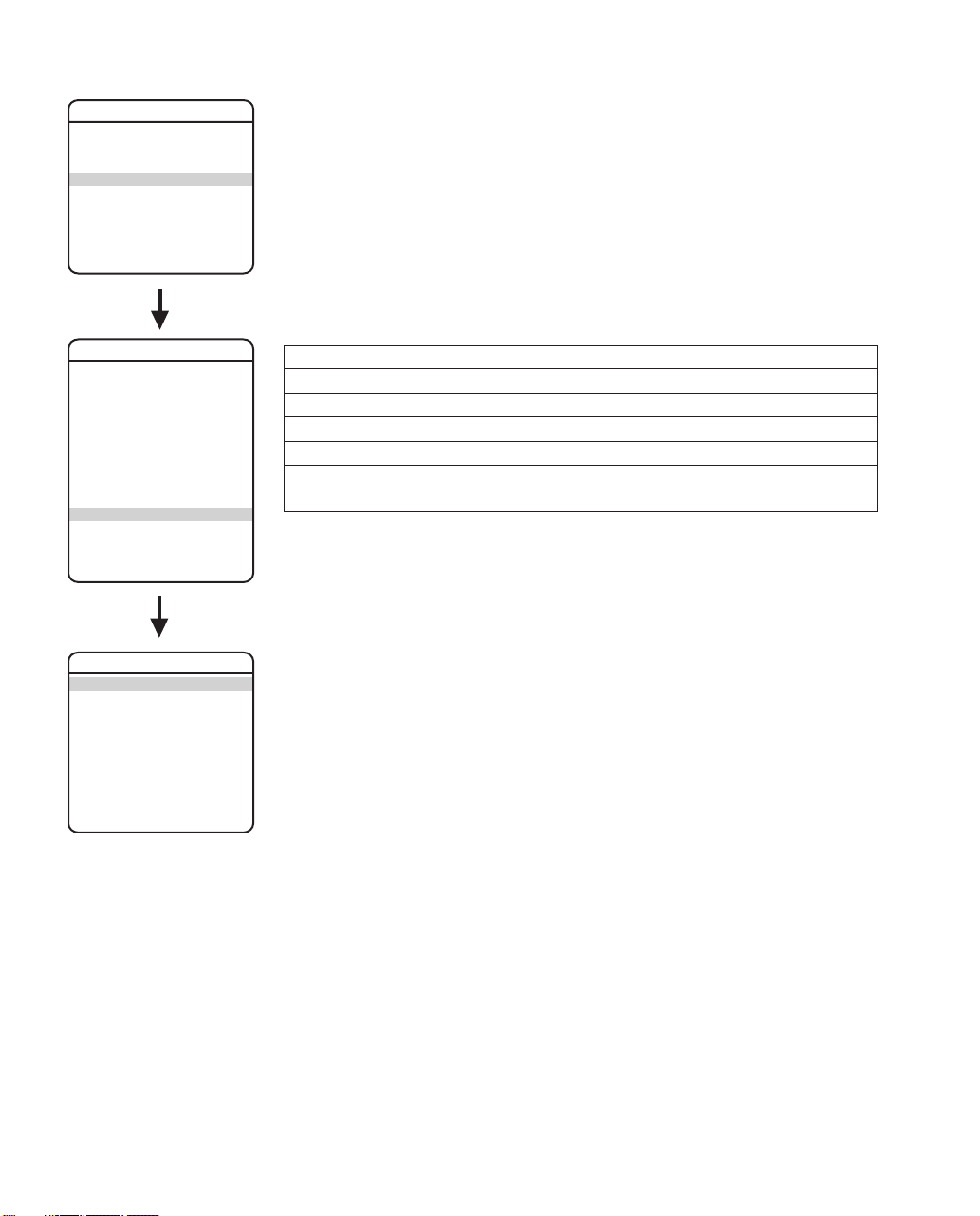
Alert
SPECTRA III
LANGUAGE ENGLISH
<SYSTEM INFORMATION>
<DISPLAY SETUP>
<DOME SETTINGS>
ACK ALERT*
RESET CAMERA
CYCLE CAMERA POWER
REBOOT SYSTEM
EXIT
DOME SETTINGS
<CAMERA>
<MOTION>
<POWER UP>
<LINE SYNC>
<PRESETS>
<PATTERNS>
<ZONES>
<WINDOW BLANKING>
<ALARMS>
<AUX>
<TITLE TEXT>
<ALERT>
<CLEAR>
<PASSWORD>
BACK
EXIT
NOTE: The
Alert
section only applies to Pressurized Spectra III dome systems with software
version 1.27 or higher. Spectra III systems that are not pressurized or pressurized systems that
do not have dome drive software version 1.27 or higher will not display this menu item.
Software version 1.27 or higher includes the software to monitor temperature, pressure, and
dew point for Pressurized Spectra III systems.
Sensors strategically placed inside the pressurized dome system continually monitor pressure,
temperature, and dew point. If internal conditions reach unacceptable levels, an alert message
appears on the screen describing the alert condition. Example: If pressure drops below 1 psig,
“LOW PRESSURE” is displayed on the monitor.
The following system conditions will trigger an alert message:
System Condition Alert Message
Temperature is above 140°F (60°C) HIGH TEMPERATURE
Temperature is below -40°F (-40°C). LOW TEMPERATURE
Pressure is above 11 psig. HIGH PRESSURE
Pressure is below 1 psig. LOW PRESSURE
The difference between the temperature and the dew point is DEW POINT (HIGH
less than or equal to 3°C. HUMIDITY)
The alert message will be repeatedly displayed until the system controller acknowledges the
alert condition by selecting ACK ALERT in the main menu. Once acknowledged, the alert
message changes to the programmed acknowledge action (ACK ACTION). If the alert condition
remains active after a period of time, the alert message reappears on the monitor, restarting the
alert message cycle. This cycle will continue to repeat until the alert condition is resolved.
ALERT
REPEAT CONSTANT
ACK ACTION ALWAYS ON
ACTIVATE AUX NO
<CURRENT READING>
RESET ALERT
BACK
EXIT
REPEAT
This setting programs how often an alert message is repeatedly displayed until the system
controller acknowledges the alert condition. The following are the settings for REPEAT:
CONSTANT The alert message is continuously displayed on the monitor until
acknowledged.
15 MIN The alert message is displayed every 15 minutes for a 15-second
duration until acknowledged.
30 MIN The alert message is displayed every 30 minutes for a 15-second
duration until acknowledged.
60 MIN The alert message is displayed every 60 minutes for a 15-second
duration until acknowledged.
42 C2487M-B (11/05)
Page 43

SPECTRA III
LANGUAGE ENGLISH
<SYSTEM INFORMATION>
<DISPLAY SETUP>
<DOME SETTINGS>
ACK ALERT*
RESET CAMERA
CYCLE CAMERA POWER
REBOOT SYSTEM
EXIT
ACK ACTION
Acknowledge action programs the alert label behavior after the alert condition has been
acknowledged. The following settings are available for ACK ACTION:
ALWAYS ON The alert label is displayed until alert conditions are cleared.
OFF 8 HRS The alert label is turned off for 8 hours. Label returns after 8 hours
if the alert condition persists.
OFF 24 HRS The alert label is turned off for 24 hours. Label returns after 24
hours if the alert condition persists.
OFF 48 HRS The alert label is turned off for 48 hours. Label returns after 48
hours if the alert condition persists.
DOME SETTINGS
<CAMERA>
<MOTION>
<POWER UP>
<LINE SYNC>
<PRESETS>
<PATTERNS>
<ZONES>
<WINDOW BLANKING>
<ALARMS>
<AUX>
<TITLE TEXT>
<ALERT>
<CLEAR>
<PASSWORD>
BACK
EXIT
ALERT
REPEAT CONSTANT
ACK ACTION ALWAYS ON
ACTIVATE AUX NO
<CURRENT READING>
RESET ALERT
BACK
EXIT
ACTIVATE AUX
This setting activates an auxiliary when an alert condition exists. ACTIVATE AUX settings include
the following:
NO (default) Not activated.
1 An alert condition will close AUX 1.
2 An alert condition will close AUX 2.
CURRENT READING
The Current Reading menu displays the existing status of temperature, pressure, and dew point
inside the dome system. An arrow displayed to the left of a menu item denotes that an alert
condition exists.
An up arrow indicates the reading is over the threshold. A down arrow indicates the reading is
below the threshold.
The high temperature alert occurs if the temperature is above 140°F (60°C).
The low temperature alert occurs if the temperature is below -40°F (-40°C).
The high pressure alert occurs if the pressure is above 11 psig.
The low pressure alert occurs if the pressure is below 1 psig.
The dew point (high humidity) alert occurs if the difference between the temperature and the
dew point is less than or equal to 3°C.
NOTE: The normal operating temperature inside the unit will be greater than the temperature
outside the back box due to the heat emitted by the system’s electronics.
CURRENT READING
TEMPERATURE 0°C
0°F
DEWPOINT 0°C
0°F
PRESSURE 0.0 PSIG
0.0 BAR
REFRESH
BACK
EXIT
RESET ALERT
Reset alert clears the alert condition and removes the alert label from the monitor. The system
automatically checks internal conditions 60 seconds after reset. If conditions are still unacceptable, the alert label reappears on the screen indicating further corrective action is required.
Quick Programming Guide
(See page 11)
C2487M-B (11/05) 43
Page 44

Clear
SPECTRA III
LANGUAGE ENGLISH
<SYSTEM INFORMATION>
<DISPLAY SETUP>
<DOME SETTINGS>
ACK ALERT*
RESET CAMERA
CYCLE CAMERA POWER
REBOOT SYSTEM
EXIT
DOME SETTINGS
<CAMERA>
<MOTION>
<POWER UP>
<LINE SYNC>
<PRESETS>
<PATTERNS>
<ZONES>
<WINDOW BLANKING>
<ALARMS>
<AUX>
<TITLE TEXT>
<ALERT>*
<CLEAR>
<PASSWORD>
BACK
EXIT
Use this setting to return the dome to factory default settings.
CLEAR
RESTORE FACTORY DEFAULTS
BACK
EXIT
*This setting only applies to
Pressurized Spectra III dome
systems with software version
1.27 or higher.
44 C2487M-B (11/05)
Page 45
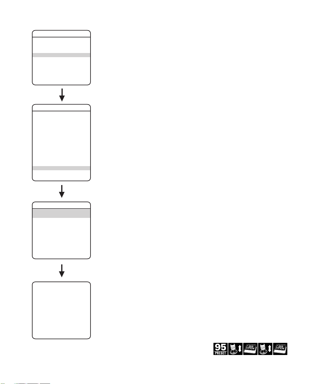
Password
SPECTRA III
LANGUAGE ENGLISH
<SYSTEM INFORMATION>
<DISPLAY SETUP>
<DOME SETTINGS>
ACK ALERT*
RESET CAMERA
CYCLE CAMERA POWER
REBOOT SYSTEM
EXIT
DOME SETTINGS
<CAMERA>
<MOTION>
<POWER UP>
<LINE SYNC>
<PRESETS>
<PATTERNS>
<ZONES>
<WINDOW BLANKING>
<ALARMS>
<AUX>
<TITLE TEXT>
<ALERT>*
<CLEAR>
<PASSWORD>
BACK
EXIT
Spectra III features password protection to prevent unauthorized changes to the dome settings.
An operator can open the System Information and Display Setup Screens, but cannot access any
of the Dome Settings menus.
Controller/keyboard commands cannot override password-protected settings. If a keyboard is
used to set a preset, pattern, or zone, the Enter Password screen appears on the monitor.
The password must be entered before programming can continue.
At least one character must be entered to create a valid password.
PASSWORD
ENABLE PASSWORD OFF
<EDIT PASSWORD>
BACK
EXIT
EDIT THE PASSWORD
---------1234567890 OK
ABCDEFGHIJ CANCEL
KLMNOPQRST
UVWXYZ.,-/ SPACE
abcdefghij BACKSPACE
klmnopqrst
uvwxyz#&:*
Quick Programming Guide
*This setting only applies to Pressurized
Spectra III dome systems with software
version 1.27 or higher.
C2487M-B (11/05) 45
(See page 11)
Page 46

RESET, CYCLE POWER, REBOOT
SPECTRA III
LANGUAGE ENGLISH
<SYSTEM INFORMATION>
<DISPLAY SETUP>
<DOME SETTINGS>
ACK ALERT*
RESET CAMERA
CYCLE CAMERA POWER
REBOOT SYSTEM
EXIT
*This setting only applies to
Pressurized Spectra III dome
systems with software version
1.27 or higher.
RESET CAMERA
Use this function to reset all camera settings to factory default parameters.
CYCLE CAMERA POWER
If the camera is not operating or if you lose camera control, cycle camera power. Cycling camera
power resets the camera but does not change any saved camera settings.
REBOOT SYSTEM
Reboot the system if it is not operating or if there is no control. Rebooting the system will cycle
dome and camera power without changing programmed dome settings.
46 C2487M-B (11/05)
Page 47

SOFTWARE/LANGUAGE FILE UPLOAD
The RJ-45 data port of the dome drive allows access for on-site setup, testing, and uploading of
revised operating software and language files. A Pelco field service tool is required to perform
these operations. Field service tools include Pelco’s remote monitor kit (IPS-RMK), remote data
port box (IPS-RDPE-2), and remote monitor cable (IPS-CABLE).
For instructions on how to upload revised operating software and language files refer to the
Installation/Operation manual supplied with the field service tool.
NOTE: Only perform software uploads when necessary. Software uploads do not need to be
performed if the dome system is operating properly.
Upload Icon
During a software/language file upload, an icon will appear on the monitor to indicate data is
being transferred to the Spectra dome system (refer to the figure below). The default setting for
data transmission is 115.2 KB per second. Noisy and long-run connections will slow the
transmission rate.
Upload Icon
C2487M-B (11/05) 47
Page 48

SPECIFICATIONS
DD53CBW18
Signal Format NTSC
Scanning System 2:1 Interlace
Image Sensor 1/4-inch CCD
Effective Pixels 724 (H) X 494 (V)
Horizontal Resolution >470 TV lines
Lens F1.6 (f=3.8~68.4 mm optical, 18X optical zoom, 10X digital zoom)
Zoom Speed (optical range) 2.9/4.2/5.8 seconds
Horizontal Angle of View 51° at 3.8 mm wide zoom; 3° at 68.4 mm telephoto zoom
Focus Automatic with manual override
Maximum Sensitivity at 35 IRE 0.08 lux at 1/2 sec. shutter speed (color)
0.3 lux at 1/60 sec. shutter speed (B-W)
0.013 lux at 1/2 sec. shutter speed (B-W)
Sync System Internal/AC line lock, phase adjustable via remote control, V-Sync
White Balance Automatic with manual override
Shutter Speed Automatic (electronic iris)/manual
1/2 ~ 1/30,000
Iris Control Automatic iris control with manual override
Gain Control Automatic/off
Video Output 1 Vp-p, 75 ohms
Video Signal to Noise >50 dB
DD53CBW18-X
Signal Format PAL
Scanning System 2:1 Interlace
Image Sensor 1/4-inch CCD
Effective Pixels 724 (H) X 582 (V)
Horizontal Resolution >470 TV lines
Lens F1.6 (f=3.8~68.4 mm optical, 18X optical zoom, 10X digital zoom)
Zoom Speed (optical range) 2.9/4.2/5.8 seconds
Horizontal Angle of View 51° at 3.8 mm wide zoom; 3° at 68.4 mm telephoto zoom
Focus Automatic with manual override
Maximum Sensitivity at 35 IRE 0.08 lux at 1/1.5 sec. shutter speed (color)
0.3 lux at 1/50 sec. shutter speed (B-W)
0.013 lux at 1/1.5 sec. shutter speed (B-W)
Sync System Internal/AC line lock, phase adjustable via remote control, V-sync
White Balance Automatic with manual override
Shutter Speed Automatic (electronic iris)/manual
1/1.5 ~ 1/30,000
Iris Control Automatic iris control with manual override
Gain Control Automatic/off
Video Output 1 Vp-p, 75 ohms
Video Signal to Noise >5 0 dB
48 C2487M-B (11/05)
Page 49

REGULATORY NOTICES
This device complies with part 15 of the FCC Rules. Operation is subject to the following two conditions: (1) this device may not
cause harmful interference, and (2) this device must accept any interference received, including interference that may cause
undesired operation.
RADIO AND TELEVISION INTERFERENCE
This equipment has been tested and found to comply with the limits of a Class B digital device, pursuant to part 15 of the FCC rules.
These limits are designed to provide reasonable protection against harmful interference in a residential installation. This equipment
generates, uses, and can radiate radio frequency energy and, if not installed and used in accordance with the instructions, may
cause harmful interference to radio communications. However there is no guarantee that the interference will not occur in a
particular installation. If this equipment does cause harmful interference to radio or television reception, which can be determined
by turning the equipment off and on, the user is encouraged to try to correct the interference by one or more of the following
measures:
• Reorient or relocate the receiving antenna.
• Increase the separation between the equipment and the receiver.
• Connect the equipment into an outlet on a circuit different from that to which the receiver is connected.
• Consult the dealer or an experienced radio/TV technician for help.
You may also find helpful the following booklet, prepared by the FCC: “How to Identify and Resolve Radio-TV Interference
Problems.” This booklet is available from the U.S. Government Printing Office, Washington D.C. 20402.
Changes and Modifications not expressly approved by the manufacturer or registrant of this equipment can void your authority to
operate this equipment under Federal Communications Commission’s rules.
REVISION HISTORY
Manual # Date Comments
C2487M 2/05 Original version.
C2487M-A 4/05 Revised scanning system information. Updated layout.
C2487M-B 11/05 Made manual changes for Spectra III software version 1.28 per ECO 05-11592. Added information to
Pelco, the Pelco logo, and Genex are registered trademarks of Pelco. ©Copyright 2005, Pelco.
Spectra III and PelcoNet are trademarks of Pelco. All rights reserved.
C2487M-B (11/05) 49
access preset 95 from the WS5050 and VCD5000.
Page 50

Page 51

Page 52

World Headquarters
3500 Pelco Way
Clovis, California 93612 USA
USA & Canada
Tel: 800/289-9100
Fax: 800/289-9150
International
Tel: 1-559/292-1981
Fax: 1-559/348-1120
www.pelco.com
ISO9001
United States | Canada | United Kingdom | The Netherlands | Singapore | Spain | Scandinavia | France | Middle East
 Loading...