

Page 1
®
DX9000 Series
Video Storage Unit
Installation/
Operation Manual
C684M-A (7/01)
U
®
L
LISTED
Pelco • 3500 Pelco Way • Clovis, CA 93612-5699 USA • Pelco Online @ www.pelco.com
In North America and Canada: Tel (800) 289-9100 • FAX (800) 289-9150 • DataFAX (800) 289-9108
International Customers: Tel +1(559) 292-1981 • FAX +1(559) 348-1120 • DataFAX +1(559) 292-0435
PelcoEurope BV • Dillenburg Center, Dillenburgstraat 7C • 5652 AM Eindhoven • The Netherlands
Tel +31(40) 251-9870 • FAX +31(40) 251-9835
Page 2
DESCRIPTION
INSTALLATION
READ BEFORE BEGINNING
YOUR INSTALLATION
The DX9000 system consists of
three major components: digital
video recorders (also referred to
as servers), video storage units,
and ViewStations (computers).
Each piece of equipment is
boxed separately and comes
with its own documentation.
It is important that the equipment be installed in the proper
sequence. Get the manuals for
all three types of equipment.
Keep the manuals together
because you will have to go
back and forth between the
manuals as you install the
equipment.
Start the installation with the
recorders. Refer to the Installation/
Operation Manual for the Digital
Video Recorder.
The DX9000 Series Video Storage Unit is one of the components of the DX9000 Series
Digital Video Recorder system. The storage unit contains hard disks for storing video information from the DX9000 Series Digital Video Recorder. A total of four storage units can be
connected to each recorder.
MODELS
DX9219HDD Storage unit with three hard disk drives totaling 219 GB
DX9438HDD Storage unit with six hard disk drives totaling 438 GB
DX9657HDD Storage unit with nine hard disk drives totaling 657 GB
Make sure all parts are present.
1Video Storage Unit
1 SCSI cable
2 Power cords (1 USA standard and 1 European standard)
2 Adjustable support rails
8 Screws, 10-32 x .375-inch
8 10-32 nuts
4 Screws, 10-32 x .750-inch, Phillips, pan head, with washers
2 Keys
MOUNTING
Install all storage units that will connect to the same recorder. The video storage unit may be
placed on a flat surface, such as a shelf, or it can be installed in a 19-inch (48.26 cm) equipment rack.
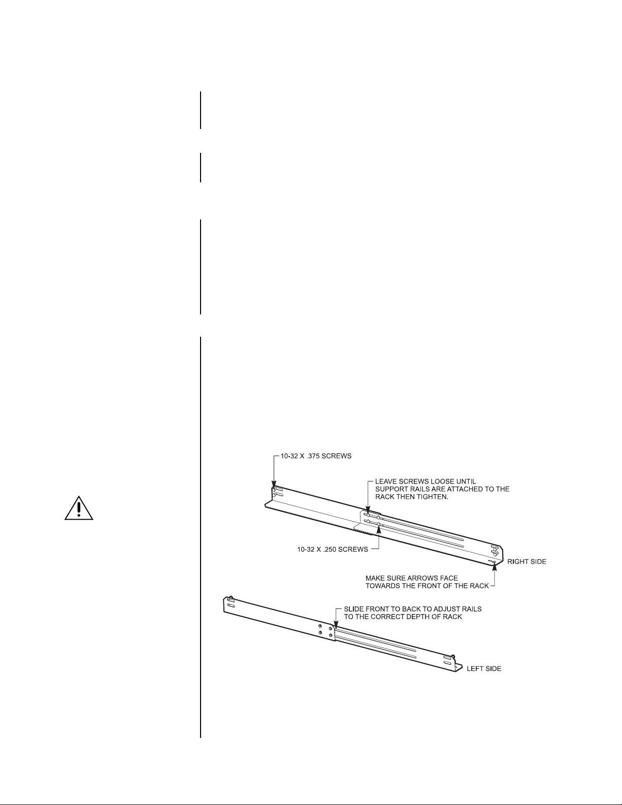
To install a storage unit in an equipment rack:
1. Attach the two adjustable support rails to the sides of the equipment rack. Refer the
Figure 1. Use the eight 10-32 x .375-inch screws. If the rack does not have threaded
mounting holes, also use the eight 10-32 nuts.
2. Place the unit on the support rails and fasten the rack ears to the rack with the four
10-32 x .750-inch, black, Phillips, pan head screws.
CAUTION:
storage unit has been
pre-configured to
operate with a specific recorder.
The storage units must be connected to the proper recorder
and in the proper order for the
system to operate properly.
There is a label on the outside of
the packing box and also on the
rear panel of the equipment. The
recorder’s label will have a name
followed by a number 1, 2, 3,
etc. The storage unit’s label will
have the same name followed by
two sets of numbers, for
example, 1-01. The first number
is the recorder to which the
storage unit is to be connected.
The second number designates
the SCSI connection location on
the rear panel of the recorder.
For this reason, consider
mounting the recorder and
storage units in a logical order.
Each
Figure 1. Installation of Support Rails
2 Pelco Manual C684M-A (7/01)
00773
Page 3

NOTE:
All video storage units
connected to a recorder must
be turned on
before
turning
on the recorder.
CONNECTIONS
One, two, three, or four video storage units can be connected to a recorder, depending on
the requirements of your system.
Refer to Figure 2 to install the storage units.
1. Connect the appropriate end of the SCSI cable to the SCSI connector on each video
storage unit.
2. Read the Caution Notice in the
SCSI cable from each video storage unit to the SCSI connector in slot 1 of the recorder. Connect the first storage unit (labeled 01) to the upper left connector. Connect
the second storage unit (labeled 02) to the upper right connector. Connect the third
storage unit (labeled 03) to the lower left connector. Connect the fourth storage unit
(labeled 04) to the lower right connector.
3. Select the appropriate power cord (USA or European standard) and plug it into the
power receptacle on the back of each video storage unit. Plug the other end into a
power supply, preferably through an uninterruptible power supply.
4. Turn on the power switch on the back of one of the video storage units. Then open the
front door with the supplied key. Press the square button to turn on the power. Close
the door. The LEDs on the front of the unit light to show the hard drives are working.
5. Repeat step 4 for each storage unit.
6. Turn on the power switch on the back of the recorder. Then open the front door with
the supplied key. Press the square button to turn on the power. Close the door.
7. Go to the
Digital Video Recorder to continue with the installation procedure.
System Configuration
RECORDER
Mounting
section. Connect the other end of the
section of the Installation/Operation Manual for the
STORAGE UNIT #1
STORAGE UNIT #3
** STORAGE UNITS ARE NUMBERED AND MUST BE CONNECTED TO THE PROPER CONNECTOR.
*
*
STORAGE UNIT #2
STORAGE UNIT #4
*
*
Figure 2. Connection Storage Units to Recorder
00850
Pelco Manual C684M-A (7/01) 3
Page 4

SPECIFICATIONS
ELECTRICAL/VIDEO
Input Voltage: 100-240 VAC, 50/60 Hz, auto-ranging
Power Consumption: 250W maximum
Recording Resolution
NTSC: 352 x 240 pixels
PAL: 384 x 288 pixels
Compression: MPEG1
Compressed Image Size: 352 x 240; average 1.4 kB
Remote Control: Full remote control via TCP/IP network
MECHANICAL
SCSI Connector: Recorder interface
GENERAL
Operating Temperature: 41° to 104°F (5° to 40°C)
Relative Humidity: Maximum 80% non-condensing
Dimensions
Desktop: 7.3 (H) x 17.0 (W) x 19.6 (D) inches (18.5 x 43.2 x 49.8 cm)
Rack Mount: 7.0 (H) x 19.0 (W) x 19.6 (D) inches (17.8 x 48.3 x 49.8 cm)
Unit weight: 45 lb (20.4 kg) maximum (fully equipped)
(Design and product specifications subject to change without notice.)
REGULATORY NOTICES
This equipment has been tested and found to comply with the limits of a Class A digital device, pursuant to part 15 of the FCC rules. These limits are designed to provide reasonable
protection against harmful interference when the equipment is operated in a commercial environment. This equipment generates, uses, and can radiate radio frequency energy and, if not
installed and used in accordance with the instruction manual, may cause harmful interference
to radio communications. Operation of this equipment in a residential area is likely to cause
harmful interference in which case the user will be required to correct the interference at his
own expense.
WARRANTY AND RETURN INFORMATION
WARRANTY
Pelco will repair or replace, without charge, any merchandise proved defective
in material or workmanship for a period of one year after the date of shipment.
Exceptions to this warranty are as noted below:
• Five years on Pelco manufactured cameras (CC3500/CC3600 and MC3500/
MC3600 Series); two years on all other cameras.
• Three years on Genex™ Series (multiplexers, server, and keyboard).
•Two years on all standard motorized and fixed focal length lenses.
•Two years on Legacy®, Camclosure™ Camera Systems, CM6700/CM6800/
CM8500/CM9500/CM9740/CM9750/CM9760 Matrix, DF5 Series and DF8
Fixed Dome products.
•Two years on Spectra® and Esprit™, including when used in continuous motion applications.
•Two years on WW5700 series window wiper (excluding wiper blades).
• Eighteen months on DX Series digital video recorders.
• Six months on all pan and tilts, scanners or preset lenses used in continuous motion applications (that is, preset scan, tour and auto scan modes).
Pelco assumes no risk and shall be subject to no liability for damages or loss
resulting from the specific use or application made of the Products. Pelco’s liability for any claim, whether based on breach of contract, negligence, infringement of any rights of any party or product liability, relating to the Products shall
not exceed the price paid by the Dealer to Pelco for such Products. In no event
will Pelco be liable for any special, incidental or consequential damages (including loss of use, loss of profit and claims of third parties) however caused, whether
by the negligence of Pelco or otherwise.
The above warranty provides the Dealer with specific legal rights. The Dealer
may also have additional rights, which are subject to variation from state to state.
REVISION HISTORY
Manual # Date Comments
C684M 4/01 Original version.
C684M-A 7/01 Revised
Description, Installation,
and
Connections
If a warranty repair is required, the Dealer must contact Pelco at (800) 289-9100
or (559) 292-1981 to obtain a Repair Authorization number (RA), and provide
the following information:
1. Model and serial number
2. Date of shipment, P.O. number , Sales Order number , or Pelco invoice number
3. Details of the defect or problem
If there is a dispute regarding the warranty of a product which does not fall under
the warranty conditions stated above, please include a written explanation with
the product when returned.
Method of return shipment shall be the same or equal to the method by which
the item was received by Pelco.
RETURNS
In order to expedite parts returned to the factory for repair or credit, please call
the factory at (800) 289-9100 or (559) 292-1981 to obtain an authorization number
(CA number if returned for credit, and RA number if returned for repair). Goods
returned for repair or credit should be clearly identified with the assigned CA/RA
number and freight should be prepaid. All merchandise returned for credit may
be subject to a 20% restocking and refurbishing charge.
Ship freight prepaid to: Pelco
3500 Pelco Way
Clovis, CA 93612-5699
sections. Added FCC notice.
® Pelco, the Pelco logo, Spectra, Genex, and Legacy are registered trademarks of Pelco. © Copyright 2001, Pelco
™ Esprit and Camclosure are trademarks of Pelco. All rights reserved.
4 Pelco Manual C684M-A (7/01)
 Loading...