

Page 1

C1553M-B (4/05)
Server
Configuration
Manual
Page 2

Page 3

C1553M-B (4/05) 3
Contents
Introduction . . . . . . . . . . . . . . . . . . . . . . . . . . . . . . . . . . . . . . . . . . . . . . . . . . . . . . . . . . . . . . . . . . . . . . . . . . . . . . . . . . . . . . . . . . . . . . . . . . . . . . . . .17
Configuring a New System . . . . . . . . . . . . . . . . . . . . . . . . . . . . . . . . . . . . . . . . . . . . . . . . . . . . . . . . . . . . . . . . . . . . . . . . . . . . . . . . . . . . . . . . . . . . .18
Set Up the Minimal Configuration . . . . . . . . . . . . . . . . . . . . . . . . . . . . . . . . . . . . . . . . . . . . . . . . . . . . . . . . . . . . . . . . . . . . . . . . . . . . . . . . . . .18
Test the Minimal Configuration . . . . . . . . . . . . . . . . . . . . . . . . . . . . . . . . . . . . . . . . . . . . . . . . . . . . . . . . . . . . . . . . . . . . . . . . . . . . . . . . . . . . .19
Log On and Configure Operating System Settings . . . . . . . . . . . . . . . . . . . . . . . . . . . . . . . . . . . . . . . . . . . . . . . . . . . . . . . . . . . . . . . . . . . . . . . . . . .20
Configure Operating System Settings . . . . . . . . . . . . . . . . . . . . . . . . . . . . . . . . . . . . . . . . . . . . . . . . . . . . . . . . . . . . . . . . . . . . . . . . . . . . . . . . 20
Assign an IP Address to the VMX300(-E) Workstation . . . . . . . . . . . . . . . . . . . . . . . . . . . . . . . . . . . . . . . . . . . . . . . . . . . . . . . . . . . . . .20
Identify the VMX300(-E) Workstation on the Network . . . . . . . . . . . . . . . . . . . . . . . . . . . . . . . . . . . . . . . . . . . . . . . . . . . . . . . . . . . . . .22
Disable NetBIOS . . . . . . . . . . . . . . . . . . . . . . . . . . . . . . . . . . . . . . . . . . . . . . . . . . . . . . . . . . . . . . . . . . . . . . . . . . . . . . . . . . . . . . . . . . . . 23
Starting and Stopping the Server . . . . . . . . . . . . . . . . . . . . . . . . . . . . . . . . . . . . . . . . . . . . . . . . . . . . . . . . . . . . . . . . . . . . . . . . . . . . . . . . . . . . . . . . 25
Launch the Server . . . . . . . . . . . . . . . . . . . . . . . . . . . . . . . . . . . . . . . . . . . . . . . . . . . . . . . . . . . . . . . . . . . . . . . . . . . . . . . . . . . . . . . . . . . . . . . 26
Configure the Server While It Is Running . . . . . . . . . . . . . . . . . . . . . . . . . . . . . . . . . . . . . . . . . . . . . . . . . . . . . . . . . . . . . . . . . . . . . . . . . . . . .27
Log Out of Configuration Mode and Launch Run Mode . . . . . . . . . . . . . . . . . . . . . . . . . . . . . . . . . . . . . . . . . . . . . . . . . . . . . . . . . . . . . . . . . .27
Shut Down the Server . . . . . . . . . . . . . . . . . . . . . . . . . . . . . . . . . . . . . . . . . . . . . . . . . . . . . . . . . . . . . . . . . . . . . . . . . . . . . . . . . . . . . . . . . . . .28
Shutting Down While in Run Mode . . . . . . . . . . . . . . . . . . . . . . . . . . . . . . . . . . . . . . . . . . . . . . . . . . . . . . . . . . . . . . . . . . . . . . . . . . . . .28
Shutting Down While in Configuration Mode Only . . . . . . . . . . . . . . . . . . . . . . . . . . . . . . . . . . . . . . . . . . . . . . . . . . . . . . . . . . . . . . . . .28
License Manager . . . . . . . . . . . . . . . . . . . . . . . . . . . . . . . . . . . . . . . . . . . . . . . . . . . . . . . . . . . . . . . . . . . . . . . . . . . . . . . . . . . . . . . . . . . . . . . . . . . .29
Add a License . . . . . . . . . . . . . . . . . . . . . . . . . . . . . . . . . . . . . . . . . . . . . . . . . . . . . . . . . . . . . . . . . . . . . . . . . . . . . . . . . . . . . . . . . . . . . . . . . . .29
Delete a License . . . . . . . . . . . . . . . . . . . . . . . . . . . . . . . . . . . . . . . . . . . . . . . . . . . . . . . . . . . . . . . . . . . . . . . . . . . . . . . . . . . . . . . . . . . . . . . .30
Starting and Stopping Device Drivers . . . . . . . . . . . . . . . . . . . . . . . . . . . . . . . . . . . . . . . . . . . . . . . . . . . . . . . . . . . . . . . . . . . . . . . . . . . . . . . . . . . .31
Start a Device Driver . . . . . . . . . . . . . . . . . . . . . . . . . . . . . . . . . . . . . . . . . . . . . . . . . . . . . . . . . . . . . . . . . . . . . . . . . . . . . . . . . . . . . . . . . . . . .31
Shut Down a Device Driver . . . . . . . . . . . . . . . . . . . . . . . . . . . . . . . . . . . . . . . . . . . . . . . . . . . . . . . . . . . . . . . . . . . . . . . . . . . . . . . . . . . . . . . .32
Clients, Custom Windows, and Canvases . . . . . . . . . . . . . . . . . . . . . . . . . . . . . . . . . . . . . . . . . . . . . . . . . . . . . . . . . . . . . . . . . . . . . . . . . . . . . . . . .33
Clients . . . . . . . . . . . . . . . . . . . . . . . . . . . . . . . . . . . . . . . . . . . . . . . . . . . . . . . . . . . . . . . . . . . . . . . . . . . . . . . . . . . . . . . . . . . . . . . . . . . . . . . .33
Workspaces . . . . . . . . . . . . . . . . . . . . . . . . . . . . . . . . . . . . . . . . . . . . . . . . . . . . . . . . . . . . . . . . . . . . . . . . . . . . . . . . . . . . . . . . . . . . . . .33
Add a New Client . . . . . . . . . . . . . . . . . . . . . . . . . . . . . . . . . . . . . . . . . . . . . . . . . . . . . . . . . . . . . . . . . . . . . . . . . . . . . . . . . . . . . . . . . . .34
Edit a Client’s Properties . . . . . . . . . . . . . . . . . . . . . . . . . . . . . . . . . . . . . . . . . . . . . . . . . . . . . . . . . . . . . . . . . . . . . . . . . . . . . . . . . . . . .34
Delete a Client . . . . . . . . . . . . . . . . . . . . . . . . . . . . . . . . . . . . . . . . . . . . . . . . . . . . . . . . . . . . . . . . . . . . . . . . . . . . . . . . . . . . . . . . . . . . . 35
Custom Windows . . . . . . . . . . . . . . . . . . . . . . . . . . . . . . . . . . . . . . . . . . . . . . . . . . . . . . . . . . . . . . . . . . . . . . . . . . . . . . . . . . . . . . . . . . . . . . . .35
How Many Custom Windows to Configure . . . . . . . . . . . . . . . . . . . . . . . . . . . . . . . . . . . . . . . . . . . . . . . . . . . . . . . . . . . . . . . . . . . . . . .35
Add a New Custom Window . . . . . . . . . . . . . . . . . . . . . . . . . . . . . . . . . . . . . . . . . . . . . . . . . . . . . . . . . . . . . . . . . . . . . . . . . . . . . . . . . . 36
Edit a Custom Window . . . . . . . . . . . . . . . . . . . . . . . . . . . . . . . . . . . . . . . . . . . . . . . . . . . . . . . . . . . . . . . . . . . . . . . . . . . . . . . . . . . . . . . 36
Delete a Custom Window . . . . . . . . . . . . . . . . . . . . . . . . . . . . . . . . . . . . . . . . . . . . . . . . . . . . . . . . . . . . . . . . . . . . . . . . . . . . . . . . . . . . .37
Canvases . . . . . . . . . . . . . . . . . . . . . . . . . . . . . . . . . . . . . . . . . . . . . . . . . . . . . . . . . . . . . . . . . . . . . . . . . . . . . . . . . . . . . . . . . . . . . . . . . . . . . .37
Add a New Canvas (General) . . . . . . . . . . . . . . . . . . . . . . . . . . . . . . . . . . . . . . . . . . . . . . . . . . . . . . . . . . . . . . . . . . . . . . . . . . . . . . . . . .37
Add a New Canvas (PelcoNet) . . . . . . . . . . . . . . . . . . . . . . . . . . . . . . . . . . . . . . . . . . . . . . . . . . . . . . . . . . . . . . . . . . . . . . . . . . . . . . . . .39
Add a New Canvas (DX8000 or DX9000 DVR) . . . . . . . . . . . . . . . . . . . . . . . . . . . . . . . . . . . . . . . . . . . . . . . . . . . . . . . . . . . . . . . . . . . . .41
Edit a Canvas . . . . . . . . . . . . . . . . . . . . . . . . . . . . . . . . . . . . . . . . . . . . . . . . . . . . . . . . . . . . . . . . . . . . . . . . . . . . . . . . . . . . . . . . . . . . . .41
Re-Order a Window’s Canvases . . . . . . . . . . . . . . . . . . . . . . . . . . . . . . . . . . . . . . . . . . . . . . . . . . . . . . . . . . . . . . . . . . . . . . . . . . . . . . . .41
Delete a Canvas . . . . . . . . . . . . . . . . . . . . . . . . . . . . . . . . . . . . . . . . . . . . . . . . . . . . . . . . . . . . . . . . . . . . . . . . . . . . . . . . . . . . . . . . . . . .41
Device Drivers . . . . . . . . . . . . . . . . . . . . . . . . . . . . . . . . . . . . . . . . . . . . . . . . . . . . . . . . . . . . . . . . . . . . . . . . . . . . . . . . . . . . . . . . . . . . . . . . . . . . . . .42
Add a New Device Driver . . . . . . . . . . . . . . . . . . . . . . . . . . . . . . . . . . . . . . . . . . . . . . . . . . . . . . . . . . . . . . . . . . . . . . . . . . . . . . . . . . . . . . . . .42
Autodiscover Device Drivers . . . . . . . . . . . . . . . . . . . . . . . . . . . . . . . . . . . . . . . . . . . . . . . . . . . . . . . . . . . . . . . . . . . . . . . . . . . . . . . . . . . . . . .43
Edit a Device Driver’s Properties . . . . . . . . . . . . . . . . . . . . . . . . . . . . . . . . . . . . . . . . . . . . . . . . . . . . . . . . . . . . . . . . . . . . . . . . . . . . . . . . . . . . 44
Delete a Device Driver . . . . . . . . . . . . . . . . . . . . . . . . . . . . . . . . . . . . . . . . . . . . . . . . . . . . . . . . . . . . . . . . . . . . . . . . . . . . . . . . . . . . . . . . . . . .44
Configure a PelcoNet MPEG Time Server . . . . . . . . . . . . . . . . . . . . . . . . . . . . . . . . . . . . . . . . . . . . . . . . . . . . . . . . . . . . . . . . . . . . . . . . . . . . .45
Devices . . . . . . . . . . . . . . . . . . . . . . . . . . . . . . . . . . . . . . . . . . . . . . . . . . . . . . . . . . . . . . . . . . . . . . . . . . . . . . . . . . . . . . . . . . . . . . . . . . . . . . . . . . . . 47
Add a New Device . . . . . . . . . . . . . . . . . . . . . . . . . . . . . . . . . . . . . . . . . . . . . . . . . . . . . . . . . . . . . . . . . . . . . . . . . . . . . . . . . . . . . . . . . . . . . . . 47
Page 4

4 C1553M-B (4/05)
Autodiscover Devices . . . . . . . . . . . . . . . . . . . . . . . . . . . . . . . . . . . . . . . . . . . . . . . . . . . . . . . . . . . . . . . . . . . . . . . . . . . . . . . . . . . . . . . . . . . .47
Delete a Device . . . . . . . . . . . . . . . . . . . . . . . . . . . . . . . . . . . . . . . . . . . . . . . . . . . . . . . . . . . . . . . . . . . . . . . . . . . . . . . . . . . . . . . . . . . . . . . . .48
Add a Fixed Camera Device . . . . . . . . . . . . . . . . . . . . . . . . . . . . . . . . . . . . . . . . . . . . . . . . . . . . . . . . . . . . . . . . . . . . . . . . . . . . . . . . . . . . . . . .48
Configure the General Tab . . . . . . . . . . . . . . . . . . . . . . . . . . . . . . . . . . . . . . . . . . . . . . . . . . . . . . . . . . . . . . . . . . . . . . . . . . . . . . . . . . . .48
Configure the Properties Tab . . . . . . . . . . . . . . . . . . . . . . . . . . . . . . . . . . . . . . . . . . . . . . . . . . . . . . . . . . . . . . . . . . . . . . . . . . . . . . . . . .49
Add a Pelco PTZ Device . . . . . . . . . . . . . . . . . . . . . . . . . . . . . . . . . . . . . . . . . . . . . . . . . . . . . . . . . . . . . . . . . . . . . . . . . . . . . . . . . . . . . . . . . . . 49
Configure the General Tab . . . . . . . . . . . . . . . . . . . . . . . . . . . . . . . . . . . . . . . . . . . . . . . . . . . . . . . . . . . . . . . . . . . . . . . . . . . . . . . . . . . .50
Configure the Properties Tab . . . . . . . . . . . . . . . . . . . . . . . . . . . . . . . . . . . . . . . . . . . . . . . . . . . . . . . . . . . . . . . . . . . . . . . . . . . . . . . . . .50
Configure the Communications Tab . . . . . . . . . . . . . . . . . . . . . . . . . . . . . . . . . . . . . . . . . . . . . . . . . . . . . . . . . . . . . . . . . . . . . . . . . . . . .51
Configure the Camera Model Tab . . . . . . . . . . . . . . . . . . . . . . . . . . . . . . . . . . . . . . . . . . . . . . . . . . . . . . . . . . . . . . . . . . . . . . . . . . . . . .53
Configure the Auxiliaries Tab . . . . . . . . . . . . . . . . . . . . . . . . . . . . . . . . . . . . . . . . . . . . . . . . . . . . . . . . . . . . . . . . . . . . . . . . . . . . . . . . . . 53
Add a PelcoNet MPEG Device . . . . . . . . . . . . . . . . . . . . . . . . . . . . . . . . . . . . . . . . . . . . . . . . . . . . . . . . . . . . . . . . . . . . . . . . . . . . . . . . . . . . . . 54
Configure the General Tab . . . . . . . . . . . . . . . . . . . . . . . . . . . . . . . . . . . . . . . . . . . . . . . . . . . . . . . . . . . . . . . . . . . . . . . . . . . . . . . . . . . .54
Configure the Properties Tab . . . . . . . . . . . . . . . . . . . . . . . . . . . . . . . . . . . . . . . . . . . . . . . . . . . . . . . . . . . . . . . . . . . . . . . . . . . . . . . . . .55
Configure the Encoding Tab . . . . . . . . . . . . . . . . . . . . . . . . . . . . . . . . . . . . . . . . . . . . . . . . . . . . . . . . . . . . . . . . . . . . . . . . . . . . . . . . . . .57
How to Choose the Video Stream Settings for Your Configuration . . . . . . . . . . . . . . . . . . . . . . . . . . . . . . . . . . . . . . . . . . . . . . . . . . . . .59
Configure the Encoding/Decoding Tab (PelcoNet 4001A only) . . . . . . . . . . . . . . . . . . . . . . . . . . . . . . . . . . . . . . . . . . . . . . . . . . . . . . . .60
Configure the Communications Tab . . . . . . . . . . . . . . . . . . . . . . . . . . . . . . . . . . . . . . . . . . . . . . . . . . . . . . . . . . . . . . . . . . . . . . . . . . . . .62
Configure the NVR300 Recording Tab . . . . . . . . . . . . . . . . . . . . . . . . . . . . . . . . . . . . . . . . . . . . . . . . . . . . . . . . . . . . . . . . . . . . . . . . . . .63
Add an External Monitor Device . . . . . . . . . . . . . . . . . . . . . . . . . . . . . . . . . . . . . . . . . . . . . . . . . . . . . . . . . . . . . . . . . . . . . . . . . . . . . . . . . . . .65
Configure the General Tab . . . . . . . . . . . . . . . . . . . . . . . . . . . . . . . . . . . . . . . . . . . . . . . . . . . . . . . . . . . . . . . . . . . . . . . . . . . . . . . . . . . .65
Configure the Properties Tab . . . . . . . . . . . . . . . . . . . . . . . . . . . . . . . . . . . . . . . . . . . . . . . . . . . . . . . . . . . . . . . . . . . . . . . . . . . . . . . . . .65
Add a DX8000 DVR . . . . . . . . . . . . . . . . . . . . . . . . . . . . . . . . . . . . . . . . . . . . . . . . . . . . . . . . . . . . . . . . . . . . . . . . . . . . . . . . . . . . . . . . . . . . . . 66
Preparing To Configure the DX8000 DVR . . . . . . . . . . . . . . . . . . . . . . . . . . . . . . . . . . . . . . . . . . . . . . . . . . . . . . . . . . . . . . . . . . . . . . . . . 66
Add a DX8000 DVR to the Server Configuration . . . . . . . . . . . . . . . . . . . . . . . . . . . . . . . . . . . . . . . . . . . . . . . . . . . . . . . . . . . . . . . . . . . 66
Configure the General Tab . . . . . . . . . . . . . . . . . . . . . . . . . . . . . . . . . . . . . . . . . . . . . . . . . . . . . . . . . . . . . . . . . . . . . . . . . . . . . . . . . . . .67
Configure the Properties Tab . . . . . . . . . . . . . . . . . . . . . . . . . . . . . . . . . . . . . . . . . . . . . . . . . . . . . . . . . . . . . . . . . . . . . . . . . . . . . . . . . .67
Configure the Communications Tab . . . . . . . . . . . . . . . . . . . . . . . . . . . . . . . . . . . . . . . . . . . . . . . . . . . . . . . . . . . . . . . . . . . . . . . . . . . . .68
Configure the Model Tab . . . . . . . . . . . . . . . . . . . . . . . . . . . . . . . . . . . . . . . . . . . . . . . . . . . . . . . . . . . . . . . . . . . . . . . . . . . . . . . . . . . . .68
Add a DX8000 Camera . . . . . . . . . . . . . . . . . . . . . . . . . . . . . . . . . . . . . . . . . . . . . . . . . . . . . . . . . . . . . . . . . . . . . . . . . . . . . . . . . . . . . . . . . . . .69
Configure the General Tab . . . . . . . . . . . . . . . . . . . . . . . . . . . . . . . . . . . . . . . . . . . . . . . . . . . . . . . . . . . . . . . . . . . . . . . . . . . . . . . . . . . .69
Configure the Properties Tab . . . . . . . . . . . . . . . . . . . . . . . . . . . . . . . . . . . . . . . . . . . . . . . . . . . . . . . . . . . . . . . . . . . . . . . . . . . . . . . . . .70
Configure the Auxiliaries Tab . . . . . . . . . . . . . . . . . . . . . . . . . . . . . . . . . . . . . . . . . . . . . . . . . . . . . . . . . . . . . . . . . . . . . . . . . . . . . . . . . . 70
Add a DX9000 DVR . . . . . . . . . . . . . . . . . . . . . . . . . . . . . . . . . . . . . . . . . . . . . . . . . . . . . . . . . . . . . . . . . . . . . . . . . . . . . . . . . . . . . . . . . . . . . . 71
Preparing to Configure the DX9000 DVR . . . . . . . . . . . . . . . . . . . . . . . . . . . . . . . . . . . . . . . . . . . . . . . . . . . . . . . . . . . . . . . . . . . . . . . . .71
Add a DX9000 DVR to the Server Configuration . . . . . . . . . . . . . . . . . . . . . . . . . . . . . . . . . . . . . . . . . . . . . . . . . . . . . . . . . . . . . . . . . . . 78
Configure the General Tab . . . . . . . . . . . . . . . . . . . . . . . . . . . . . . . . . . . . . . . . . . . . . . . . . . . . . . . . . . . . . . . . . . . . . . . . . . . . . . . . . . . .78
Configure the Properties Tab . . . . . . . . . . . . . . . . . . . . . . . . . . . . . . . . . . . . . . . . . . . . . . . . . . . . . . . . . . . . . . . . . . . . . . . . . . . . . . . . . .78
Configure the Alarms and Events Tab . . . . . . . . . . . . . . . . . . . . . . . . . . . . . . . . . . . . . . . . . . . . . . . . . . . . . . . . . . . . . . . . . . . . . . . . . . . 79
DVR Troubleshooting: If You Change the VMX300(-E) Operating System Password . . . . . . . . . . . . . . . . . . . . . . . . . . . . . . . . . . . . . . . 79
Add a Pelco ASCII Switcher . . . . . . . . . . . . . . . . . . . . . . . . . . . . . . . . . . . . . . . . . . . . . . . . . . . . . . . . . . . . . . . . . . . . . . . . . . . . . . . . . . . . . . . .79
Configure the General Tab . . . . . . . . . . . . . . . . . . . . . . . . . . . . . . . . . . . . . . . . . . . . . . . . . . . . . . . . . . . . . . . . . . . . . . . . . . . . . . . . . . . .80
Configure the Properties Tab . . . . . . . . . . . . . . . . . . . . . . . . . . . . . . . . . . . . . . . . . . . . . . . . . . . . . . . . . . . . . . . . . . . . . . . . . . . . . . . . . .80
Configure the Communications Tab . . . . . . . . . . . . . . . . . . . . . . . . . . . . . . . . . . . . . . . . . . . . . . . . . . . . . . . . . . . . . . . . . . . . . . . . . . . . .81
Configure the I/O Tab . . . . . . . . . . . . . . . . . . . . . . . . . . . . . . . . . . . . . . . . . . . . . . . . . . . . . . . . . . . . . . . . . . . . . . . . . . . . . . . . . . . . . . . .83
Configure the Model Tab . . . . . . . . . . . . . . . . . . . . . . . . . . . . . . . . . . . . . . . . . . . . . . . . . . . . . . . . . . . . . . . . . . . . . . . . . . . . . . . . . . . . .84
Add an ASCII Camera . . . . . . . . . . . . . . . . . . . . . . . . . . . . . . . . . . . . . . . . . . . . . . . . . . . . . . . . . . . . . . . . . . . . . . . . . . . . . . . . . . . . . . . . . . . .84
Configure the General Tab . . . . . . . . . . . . . . . . . . . . . . . . . . . . . . . . . . . . . . . . . . . . . . . . . . . . . . . . . . . . . . . . . . . . . . . . . . . . . . . . . . . .85
Configure the Properties Tab . . . . . . . . . . . . . . . . . . . . . . . . . . . . . . . . . . . . . . . . . . . . . . . . . . . . . . . . . . . . . . . . . . . . . . . . . . . . . . . . . .85
Configure the Auxiliaries Tab . . . . . . . . . . . . . . . . . . . . . . . . . . . . . . . . . . . . . . . . . . . . . . . . . . . . . . . . . . . . . . . . . . . . . . . . . . . . . . . . . . 86
Add a KBD300A Keyboard . . . . . . . . . . . . . . . . . . . . . . . . . . . . . . . . . . . . . . . . . . . . . . . . . . . . . . . . . . . . . . . . . . . . . . . . . . . . . . . . . . . . . . . . . 86
Add User Accounts . . . . . . . . . . . . . . . . . . . . . . . . . . . . . . . . . . . . . . . . . . . . . . . . . . . . . . . . . . . . . . . . . . . . . . . . . . . . . . . . . . . . . . . . . .86
Add a KBD300A Keyboard to the Server Configuration . . . . . . . . . . . . . . . . . . . . . . . . . . . . . . . . . . . . . . . . . . . . . . . . . . . . . . . . . . . . . . 86
Configure the General Tab . . . . . . . . . . . . . . . . . . . . . . . . . . . . . . . . . . . . . . . . . . . . . . . . . . . . . . . . . . . . . . . . . . . . . . . . . . . . . . . . . . . .87
Configure the Communications Tab . . . . . . . . . . . . . . . . . . . . . . . . . . . . . . . . . . . . . . . . . . . . . . . . . . . . . . . . . . . . . . . . . . . . . . . . . . . . .87
Using the KBD300A Logical Mapping Feature . . . . . . . . . . . . . . . . . . . . . . . . . . . . . . . . . . . . . . . . . . . . . . . . . . . . . . . . . . . . . . . . . . . . . 89
Enable Camera and Monitor Device Numbers . . . . . . . . . . . . . . . . . . . . . . . . . . . . . . . . . . . . . . . . . . . . . . . . . . . . . . . . . . . . . . . . . . . . . 90
Page 5

C1553M-B (4/05) 5
Configure the Logical Mapping Tab . . . . . . . . . . . . . . . . . . . . . . . . . . . . . . . . . . . . . . . . . . . . . . . . . . . . . . . . . . . . . . . . . . . . . . . . . . . . .91
Add a CM9760-ALM Alarm Interface Unit . . . . . . . . . . . . . . . . . . . . . . . . . . . . . . . . . . . . . . . . . . . . . . . . . . . . . . . . . . . . . . . . . . . . . . . . . . . . 93
Configure the General Tab . . . . . . . . . . . . . . . . . . . . . . . . . . . . . . . . . . . . . . . . . . . . . . . . . . . . . . . . . . . . . . . . . . . . . . . . . . . . . . . . . . . .94
Configure the Properties Tab . . . . . . . . . . . . . . . . . . . . . . . . . . . . . . . . . . . . . . . . . . . . . . . . . . . . . . . . . . . . . . . . . . . . . . . . . . . . . . . . . .94
Configure the Communications Tab . . . . . . . . . . . . . . . . . . . . . . . . . . . . . . . . . . . . . . . . . . . . . . . . . . . . . . . . . . . . . . . . . . . . . . . . . . . . .95
Configure the ALM Points Tab . . . . . . . . . . . . . . . . . . . . . . . . . . . . . . . . . . . . . . . . . . . . . . . . . . . . . . . . . . . . . . . . . . . . . . . . . . . . . . . . .97
Configure the Model Tab . . . . . . . . . . . . . . . . . . . . . . . . . . . . . . . . . . . . . . . . . . . . . . . . . . . . . . . . . . . . . . . . . . . . . . . . . . . . . . . . . . . . .98
Add a CM9760-REL Relay Interface Unit . . . . . . . . . . . . . . . . . . . . . . . . . . . . . . . . . . . . . . . . . . . . . . . . . . . . . . . . . . . . . . . . . . . . . . . . . . . . . .98
Configure the General Tab . . . . . . . . . . . . . . . . . . . . . . . . . . . . . . . . . . . . . . . . . . . . . . . . . . . . . . . . . . . . . . . . . . . . . . . . . . . . . . . . . . . .99
Configure the Properties Tab . . . . . . . . . . . . . . . . . . . . . . . . . . . . . . . . . . . . . . . . . . . . . . . . . . . . . . . . . . . . . . . . . . . . . . . . . . . . . . . . . .99
Configure the Communications Tab . . . . . . . . . . . . . . . . . . . . . . . . . . . . . . . . . . . . . . . . . . . . . . . . . . . . . . . . . . . . . . . . . . . . . . . . . . . .100
Configure the Relay Points Tab . . . . . . . . . . . . . . . . . . . . . . . . . . . . . . . . . . . . . . . . . . . . . . . . . . . . . . . . . . . . . . . . . . . . . . . . . . . . . . .102
Configure the DIP Switches Tab . . . . . . . . . . . . . . . . . . . . . . . . . . . . . . . . . . . . . . . . . . . . . . . . . . . . . . . . . . . . . . . . . . . . . . . . . . . . . . .103
Configure the Model Tab . . . . . . . . . . . . . . . . . . . . . . . . . . . . . . . . . . . . . . . . . . . . . . . . . . . . . . . . . . . . . . . . . . . . . . . . . . . . . . . . . . . .103
Add a Serial Output Device . . . . . . . . . . . . . . . . . . . . . . . . . . . . . . . . . . . . . . . . . . . . . . . . . . . . . . . . . . . . . . . . . . . . . . . . . . . . . . . . . . . . . . .104
Configure the General Tab . . . . . . . . . . . . . . . . . . . . . . . . . . . . . . . . . . . . . . . . . . . . . . . . . . . . . . . . . . . . . . . . . . . . . . . . . . . . . . . . . . .104
Configure the Properties Tab . . . . . . . . . . . . . . . . . . . . . . . . . . . . . . . . . . . . . . . . . . . . . . . . . . . . . . . . . . . . . . . . . . . . . . . . . . . . . . . . .105
Configure the Communications Tab . . . . . . . . . . . . . . . . . . . . . . . . . . . . . . . . . . . . . . . . . . . . . . . . . . . . . . . . . . . . . . . . . . . . . . . . . . . .105
Configure the Custom Buttons Tab . . . . . . . . . . . . . . . . . . . . . . . . . . . . . . . . . . . . . . . . . . . . . . . . . . . . . . . . . . . . . . . . . . . . . . . . . . . . .107
Limitations of Controlling a Serial Output Device . . . . . . . . . . . . . . . . . . . . . . . . . . . . . . . . . . . . . . . . . . . . . . . . . . . . . . . . . . . . . . . . .108
Add an IP Device Status Monitor . . . . . . . . . . . . . . . . . . . . . . . . . . . . . . . . . . . . . . . . . . . . . . . . . . . . . . . . . . . . . . . . . . . . . . . . . . . . . . . . . .109
Configure the General Tab . . . . . . . . . . . . . . . . . . . . . . . . . . . . . . . . . . . . . . . . . . . . . . . . . . . . . . . . . . . . . . . . . . . . . . . . . . . . . . . . . . .109
Configure the Properties Tab . . . . . . . . . . . . . . . . . . . . . . . . . . . . . . . . . . . . . . . . . . . . . . . . . . . . . . . . . . . . . . . . . . . . . . . . . . . . . . . . .110
Configure the Icon Animation Tab . . . . . . . . . . . . . . . . . . . . . . . . . . . . . . . . . . . . . . . . . . . . . . . . . . . . . . . . . . . . . . . . . . . . . . . . . . . . .110
Add an Access Control Device . . . . . . . . . . . . . . . . . . . . . . . . . . . . . . . . . . . . . . . . . . . . . . . . . . . . . . . . . . . . . . . . . . . . . . . . . . . . . . . . . . . . .111
How the Access Control Driver Works . . . . . . . . . . . . . . . . . . . . . . . . . . . . . . . . . . . . . . . . . . . . . . . . . . . . . . . . . . . . . . . . . . . . . . . . . . 111
Add an Access Control Device to the Server Configuration . . . . . . . . . . . . . . . . . . . . . . . . . . . . . . . . . . . . . . . . . . . . . . . . . . . . . . . . . .111
Configure the General Tab . . . . . . . . . . . . . . . . . . . . . . . . . . . . . . . . . . . . . . . . . . . . . . . . . . . . . . . . . . . . . . . . . . . . . . . . . . . . . . . . . . .112
Configure the Properties Tab . . . . . . . . . . . . . . . . . . . . . . . . . . . . . . . . . . . . . . . . . . . . . . . . . . . . . . . . . . . . . . . . . . . . . . . . . . . . . . . . .112
Configure the Communications Tab . . . . . . . . . . . . . . . . . . . . . . . . . . . . . . . . . . . . . . . . . . . . . . . . . . . . . . . . . . . . . . . . . . . . . . . . . . . .113
Configure Access Control Points . . . . . . . . . . . . . . . . . . . . . . . . . . . . . . . . . . . . . . . . . . . . . . . . . . . . . . . . . . . . . . . . . . . . . . . . . . . . . .114
Configure Pattern Matching for Incoming Alarm Strings . . . . . . . . . . . . . . . . . . . . . . . . . . . . . . . . . . . . . . . . . . . . . . . . . . . . . . . . . . . .117
Define Alarms Based on Access Control Points . . . . . . . . . . . . . . . . . . . . . . . . . . . . . . . . . . . . . . . . . . . . . . . . . . . . . . . . . . . . . . . . . . .122
Connections . . . . . . . . . . . . . . . . . . . . . . . . . . . . . . . . . . . . . . . . . . . . . . . . . . . . . . . . . . . . . . . . . . . . . . . . . . . . . . . . . . . . . . . . . . . . . . . . . . . . . . .124
Managing Connections . . . . . . . . . . . . . . . . . . . . . . . . . . . . . . . . . . . . . . . . . . . . . . . . . . . . . . . . . . . . . . . . . . . . . . . . . . . . . . . . . . . . . . . . . .124
PelcoNet Connections . . . . . . . . . . . . . . . . . . . . . . . . . . . . . . . . . . . . . . . . . . . . . . . . . . . . . . . . . . . . . . . . . . . . . . . . . . . . . . . . . . . . . . . . . . .126
DVR Connections . . . . . . . . . . . . . . . . . . . . . . . . . . . . . . . . . . . . . . . . . . . . . . . . . . . . . . . . . . . . . . . . . . . . . . . . . . . . . . . . . . . . . . . . . . . . . . .128
ASCII Connections . . . . . . . . . . . . . . . . . . . . . . . . . . . . . . . . . . . . . . . . . . . . . . . . . . . . . . . . . . . . . . . . . . . . . . . . . . . . . . . . . . . . . . . . . . . . . .129
Archive Servers . . . . . . . . . . . . . . . . . . . . . . . . . . . . . . . . . . . . . . . . . . . . . . . . . . . . . . . . . . . . . . . . . . . . . . . . . . . . . . . . . . . . . . . . . . . . . . . . . . . . .130
Start an Archive Server . . . . . . . . . . . . . . . . . . . . . . . . . . . . . . . . . . . . . . . . . . . . . . . . . . . . . . . . . . . . . . . . . . . . . . . . . . . . . . . . . . . . . . . . . .130
View Archive Server Status . . . . . . . . . . . . . . . . . . . . . . . . . . . . . . . . . . . . . . . . . . . . . . . . . . . . . . . . . . . . . . . . . . . . . . . . . . . . . . . . . . . . . . .131
Shut Down an Archive Server . . . . . . . . . . . . . . . . . . . . . . . . . . . . . . . . . . . . . . . . . . . . . . . . . . . . . . . . . . . . . . . . . . . . . . . . . . . . . . . . . . . . .132
Project Properties . . . . . . . . . . . . . . . . . . . . . . . . . . . . . . . . . . . . . . . . . . . . . . . . . . . . . . . . . . . . . . . . . . . . . . . . . . . . . . . . . . . . . . . . . . . . . . . . . . . 133
Network Tab . . . . . . . . . . . . . . . . . . . . . . . . . . . . . . . . . . . . . . . . . . . . . . . . . . . . . . . . . . . . . . . . . . . . . . . . . . . . . . . . . . . . . . . . . . . . . . . . . .133
Configure a Primary Server . . . . . . . . . . . . . . . . . . . . . . . . . . . . . . . . . . . . . . . . . . . . . . . . . . . . . . . . . . . . . . . . . . . . . . . . . . . . . . . . . . .133
Configure a Backup Server . . . . . . . . . . . . . . . . . . . . . . . . . . . . . . . . . . . . . . . . . . . . . . . . . . . . . . . . . . . . . . . . . . . . . . . . . . . . . . . . . . .134
Switching Tab . . . . . . . . . . . . . . . . . . . . . . . . . . . . . . . . . . . . . . . . . . . . . . . . . . . . . . . . . . . . . . . . . . . . . . . . . . . . . . . . . . . . . . . . . . . . . . . . . 136
Archiving Tab . . . . . . . . . . . . . . . . . . . . . . . . . . . . . . . . . . . . . . . . . . . . . . . . . . . . . . . . . . . . . . . . . . . . . . . . . . . . . . . . . . . . . . . . . . . . . . . . . . 137
Date/Time Tab . . . . . . . . . . . . . . . . . . . . . . . . . . . . . . . . . . . . . . . . . . . . . . . . . . . . . . . . . . . . . . . . . . . . . . . . . . . . . . . . . . . . . . . . . . . . . . . . . 138
E-mail Tab . . . . . . . . . . . . . . . . . . . . . . . . . . . . . . . . . . . . . . . . . . . . . . . . . . . . . . . . . . . . . . . . . . . . . . . . . . . . . . . . . . . . . . . . . . . . . . . . . . . .139
User Groups . . . . . . . . . . . . . . . . . . . . . . . . . . . . . . . . . . . . . . . . . . . . . . . . . . . . . . . . . . . . . . . . . . . . . . . . . . . . . . . . . . . . . . . . . . . . . . . . . . . . . . .141
Group Permissions . . . . . . . . . . . . . . . . . . . . . . . . . . . . . . . . . . . . . . . . . . . . . . . . . . . . . . . . . . . . . . . . . . . . . . . . . . . . . . . . . . . . . . . . . . . . . . 141
Fixed Camera Permission . . . . . . . . . . . . . . . . . . . . . . . . . . . . . . . . . . . . . . . . . . . . . . . . . . . . . . . . . . . . . . . . . . . . . . . . . . . . . . . . . . . .142
PTZ Permissions . . . . . . . . . . . . . . . . . . . . . . . . . . . . . . . . . . . . . . . . . . . . . . . . . . . . . . . . . . . . . . . . . . . . . . . . . . . . . . . . . . . . . . . . . . .143
Page 6

6 C1553M-B (4/05)
PelcoNet Device Permissions . . . . . . . . . . . . . . . . . . . . . . . . . . . . . . . . . . . . . . . . . . . . . . . . . . . . . . . . . . . . . . . . . . . . . . . . . . . . . . . . . 144
External Monitor Permission . . . . . . . . . . . . . . . . . . . . . . . . . . . . . . . . . . . . . . . . . . . . . . . . . . . . . . . . . . . . . . . . . . . . . . . . . . . . . . . . .144
DX8000 Permissions . . . . . . . . . . . . . . . . . . . . . . . . . . . . . . . . . . . . . . . . . . . . . . . . . . . . . . . . . . . . . . . . . . . . . . . . . . . . . . . . . . . . . . . . 145
DX9000 Permission . . . . . . . . . . . . . . . . . . . . . . . . . . . . . . . . . . . . . . . . . . . . . . . . . . . . . . . . . . . . . . . . . . . . . . . . . . . . . . . . . . . . . . . . .146
ASCII Device Permissions . . . . . . . . . . . . . . . . . . . . . . . . . . . . . . . . . . . . . . . . . . . . . . . . . . . . . . . . . . . . . . . . . . . . . . . . . . . . . . . . . . . .146
KBD300A Permission . . . . . . . . . . . . . . . . . . . . . . . . . . . . . . . . . . . . . . . . . . . . . . . . . . . . . . . . . . . . . . . . . . . . . . . . . . . . . . . . . . . . . . . 147
CM9760-ALM Permissions . . . . . . . . . . . . . . . . . . . . . . . . . . . . . . . . . . . . . . . . . . . . . . . . . . . . . . . . . . . . . . . . . . . . . . . . . . . . . . . . . . . 147
CM9760-REL Permissions . . . . . . . . . . . . . . . . . . . . . . . . . . . . . . . . . . . . . . . . . . . . . . . . . . . . . . . . . . . . . . . . . . . . . . . . . . . . . . . . . . . .148
Serial Output Permissions . . . . . . . . . . . . . . . . . . . . . . . . . . . . . . . . . . . . . . . . . . . . . . . . . . . . . . . . . . . . . . . . . . . . . . . . . . . . . . . . . . .148
IP Device Status Monitor Permissions . . . . . . . . . . . . . . . . . . . . . . . . . . . . . . . . . . . . . . . . . . . . . . . . . . . . . . . . . . . . . . . . . . . . . . . . . .149
The Predefined User Group . . . . . . . . . . . . . . . . . . . . . . . . . . . . . . . . . . . . . . . . . . . . . . . . . . . . . . . . . . . . . . . . . . . . . . . . . . . . . . . . . . . . . . .149
Add a New User Group . . . . . . . . . . . . . . . . . . . . . . . . . . . . . . . . . . . . . . . . . . . . . . . . . . . . . . . . . . . . . . . . . . . . . . . . . . . . . . . . . . . . . . . . . .150
Edit a User Group . . . . . . . . . . . . . . . . . . . . . . . . . . . . . . . . . . . . . . . . . . . . . . . . . . . . . . . . . . . . . . . . . . . . . . . . . . . . . . . . . . . . . . . . . . . . . . .151
Delete a User Group . . . . . . . . . . . . . . . . . . . . . . . . . . . . . . . . . . . . . . . . . . . . . . . . . . . . . . . . . . . . . . . . . . . . . . . . . . . . . . . . . . . . . . . . . . . .151
Users . . . . . . . . . . . . . . . . . . . . . . . . . . . . . . . . . . . . . . . . . . . . . . . . . . . . . . . . . . . . . . . . . . . . . . . . . . . . . . . . . . . . . . . . . . . . . . . . . . . . . . . . . . . . .152
Predefined User Accounts . . . . . . . . . . . . . . . . . . . . . . . . . . . . . . . . . . . . . . . . . . . . . . . . . . . . . . . . . . . . . . . . . . . . . . . . . . . . . . . . . . . . . . . .152
The Predefined Administrator Account . . . . . . . . . . . . . . . . . . . . . . . . . . . . . . . . . . . . . . . . . . . . . . . . . . . . . . . . . . . . . . . . . . . . . . . . .152
The Predefined Operator Account . . . . . . . . . . . . . . . . . . . . . . . . . . . . . . . . . . . . . . . . . . . . . . . . . . . . . . . . . . . . . . . . . . . . . . . . . . . . .152
Add a New User . . . . . . . . . . . . . . . . . . . . . . . . . . . . . . . . . . . . . . . . . . . . . . . . . . . . . . . . . . . . . . . . . . . . . . . . . . . . . . . . . . . . . . . . . . . . . . . .153
Edit a User . . . . . . . . . . . . . . . . . . . . . . . . . . . . . . . . . . . . . . . . . . . . . . . . . . . . . . . . . . . . . . . . . . . . . . . . . . . . . . . . . . . . . . . . . . . . . . . . . . . .155
Delete a User . . . . . . . . . . . . . . . . . . . . . . . . . . . . . . . . . . . . . . . . . . . . . . . . . . . . . . . . . . . . . . . . . . . . . . . . . . . . . . . . . . . . . . . . . . . . . 155
Maps . . . . . . . . . . . . . . . . . . . . . . . . . . . . . . . . . . . . . . . . . . . . . . . . . . . . . . . . . . . . . . . . . . . . . . . . . . . . . . . . . . . . . . . . . . . . . . . . . . . . . . . . . . . . .156
Use Print Screen to Create a Map File . . . . . . . . . . . . . . . . . . . . . . . . . . . . . . . . . . . . . . . . . . . . . . . . . . . . . . . . . . . . . . . . . . . . . . . . . . . . . . 156
Add a New Map . . . . . . . . . . . . . . . . . . . . . . . . . . . . . . . . . . . . . . . . . . . . . . . . . . . . . . . . . . . . . . . . . . . . . . . . . . . . . . . . . . . . . . . . . . . . . . . .157
Edit a Map’s Properties . . . . . . . . . . . . . . . . . . . . . . . . . . . . . . . . . . . . . . . . . . . . . . . . . . . . . . . . . . . . . . . . . . . . . . . . . . . . . . . . . . . . . . . . . .158
Load a Map . . . . . . . . . . . . . . . . . . . . . . . . . . . . . . . . . . . . . . . . . . . . . . . . . . . . . . . . . . . . . . . . . . . . . . . . . . . . . . . . . . . . . . . . . . . . . . . . . . .158
Customize Your Maps . . . . . . . . . . . . . . . . . . . . . . . . . . . . . . . . . . . . . . . . . . . . . . . . . . . . . . . . . . . . . . . . . . . . . . . . . . . . . . . . . . . . . . . . . . .159
Delete a Map . . . . . . . . . . . . . . . . . . . . . . . . . . . . . . . . . . . . . . . . . . . . . . . . . . . . . . . . . . . . . . . . . . . . . . . . . . . . . . . . . . . . . . . . . . . . . . . . . . 159
Device Settings . . . . . . . . . . . . . . . . . . . . . . . . . . . . . . . . . . . . . . . . . . . . . . . . . . . . . . . . . . . . . . . . . . . . . . . . . . . . . . . . . . . . . . . . . . . . . . . . . . . . .160
Edit a Device’s Properties . . . . . . . . . . . . . . . . . . . . . . . . . . . . . . . . . . . . . . . . . . . . . . . . . . . . . . . . . . . . . . . . . . . . . . . . . . . . . . . . . . . . . . . .160
Edit a Device’s Local Settings . . . . . . . . . . . . . . . . . . . . . . . . . . . . . . . . . . . . . . . . . . . . . . . . . . . . . . . . . . . . . . . . . . . . . . . . . . . . . . . . . . . . .161
View a Device’s Read and Write Properties . . . . . . . . . . . . . . . . . . . . . . . . . . . . . . . . . . . . . . . . . . . . . . . . . . . . . . . . . . . . . . . . . . . . . . . . . .163
Device Icons . . . . . . . . . . . . . . . . . . . . . . . . . . . . . . . . . . . . . . . . . . . . . . . . . . . . . . . . . . . . . . . . . . . . . . . . . . . . . . . . . . . . . . . . . . . . . . . . . . . . . . .164
Place a Device Icon on a Map . . . . . . . . . . . . . . . . . . . . . . . . . . . . . . . . . . . . . . . . . . . . . . . . . . . . . . . . . . . . . . . . . . . . . . . . . . . . . . . . . . . . .164
Move a Device Icon . . . . . . . . . . . . . . . . . . . . . . . . . . . . . . . . . . . . . . . . . . . . . . . . . . . . . . . . . . . . . . . . . . . . . . . . . . . . . . . . . . . . . . . . . . . . .164
Scale and Rotate a Device Icon . . . . . . . . . . . . . . . . . . . . . . . . . . . . . . . . . . . . . . . . . . . . . . . . . . . . . . . . . . . . . . . . . . . . . . . . . . . . . . . . . . . .165
Remove a Device Icon from a Map . . . . . . . . . . . . . . . . . . . . . . . . . . . . . . . . . . . . . . . . . . . . . . . . . . . . . . . . . . . . . . . . . . . . . . . . . . . . . . . . .165
Move a Device Label . . . . . . . . . . . . . . . . . . . . . . . . . . . . . . . . . . . . . . . . . . . . . . . . . . . . . . . . . . . . . . . . . . . . . . . . . . . . . . . . . . . . . . . . . . . .166
Scale a Device Label . . . . . . . . . . . . . . . . . . . . . . . . . . . . . . . . . . . . . . . . . . . . . . . . . . . . . . . . . . . . . . . . . . . . . . . . . . . . . . . . . . . . . . . . . . . .166
Edit a Device Label . . . . . . . . . . . . . . . . . . . . . . . . . . . . . . . . . . . . . . . . . . . . . . . . . . . . . . . . . . . . . . . . . . . . . . . . . . . . . . . . . . . . . . . . . . . . .167
Remove a Device Label . . . . . . . . . . . . . . . . . . . . . . . . . . . . . . . . . . . . . . . . . . . . . . . . . . . . . . . . . . . . . . . . . . . . . . . . . . . . . . . . . . . . . . . . . .167
Named Views . . . . . . . . . . . . . . . . . . . . . . . . . . . . . . . . . . . . . . . . . . . . . . . . . . . . . . . . . . . . . . . . . . . . . . . . . . . . . . . . . . . . . . . . . . . . . . . . . . . . . . 168
Add a New Named View . . . . . . . . . . . . . . . . . . . . . . . . . . . . . . . . . . . . . . . . . . . . . . . . . . . . . . . . . . . . . . . . . . . . . . . . . . . . . . . . . . . . . . . . . 168
Edit a Named View . . . . . . . . . . . . . . . . . . . . . . . . . . . . . . . . . . . . . . . . . . . . . . . . . . . . . . . . . . . . . . . . . . . . . . . . . . . . . . . . . . . . . . . . . . . . . 168
Load a Named View . . . . . . . . . . . . . . . . . . . . . . . . . . . . . . . . . . . . . . . . . . . . . . . . . . . . . . . . . . . . . . . . . . . . . . . . . . . . . . . . . . . . . . . . . . . . .169
Update a Named View . . . . . . . . . . . . . . . . . . . . . . . . . . . . . . . . . . . . . . . . . . . . . . . . . . . . . . . . . . . . . . . . . . . . . . . . . . . . . . . . . . . . . . . . . . .169
Delete a Named View . . . . . . . . . . . . . . . . . . . . . . . . . . . . . . . . . . . . . . . . . . . . . . . . . . . . . . . . . . . . . . . . . . . . . . . . . . . . . . . . . . . . . . . . . . .169
Hotlinks . . . . . . . . . . . . . . . . . . . . . . . . . . . . . . . . . . . . . . . . . . . . . . . . . . . . . . . . . . . . . . . . . . . . . . . . . . . . . . . . . . . . . . . . . . . . . . . . . . . . . . . . . . .170
Add a New Hotlink . . . . . . . . . . . . . . . . . . . . . . . . . . . . . . . . . . . . . . . . . . . . . . . . . . . . . . . . . . . . . . . . . . . . . . . . . . . . . . . . . . . . . . . . . . . . . .170
Edit a Hotlink’s Properties . . . . . . . . . . . . . . . . . . . . . . . . . . . . . . . . . . . . . . . . . . . . . . . . . . . . . . . . . . . . . . . . . . . . . . . . . . . . . . . . . . . . . . . .172
Modify a Hotlink’s Shape and Size . . . . . . . . . . . . . . . . . . . . . . . . . . . . . . . . . . . . . . . . . . . . . . . . . . . . . . . . . . . . . . . . . . . . . . . . . . . . . . . . .172
Move a Vertex . . . . . . . . . . . . . . . . . . . . . . . . . . . . . . . . . . . . . . . . . . . . . . . . . . . . . . . . . . . . . . . . . . . . . . . . . . . . . . . . . . . . . . . . . . . . .173
Page 7

C1553M-B (4/05) 7
Add a Vertex . . . . . . . . . . . . . . . . . . . . . . . . . . . . . . . . . . . . . . . . . . . . . . . . . . . . . . . . . . . . . . . . . . . . . . . . . . . . . . . . . . . . . . . . . . . . . .173
Delete a Vertex . . . . . . . . . . . . . . . . . . . . . . . . . . . . . . . . . . . . . . . . . . . . . . . . . . . . . . . . . . . . . . . . . . . . . . . . . . . . . . . . . . . . . . . . . . . . 173
Delete a Hotlink . . . . . . . . . . . . . . . . . . . . . . . . . . . . . . . . . . . . . . . . . . . . . . . . . . . . . . . . . . . . . . . . . . . . . . . . . . . . . . . . . . . . . . . . . . . . . . . . 173
Labels . . . . . . . . . . . . . . . . . . . . . . . . . . . . . . . . . . . . . . . . . . . . . . . . . . . . . . . . . . . . . . . . . . . . . . . . . . . . . . . . . . . . . . . . . . . . . . . . . . . . . . . . . . . .174
Add a New Label . . . . . . . . . . . . . . . . . . . . . . . . . . . . . . . . . . . . . . . . . . . . . . . . . . . . . . . . . . . . . . . . . . . . . . . . . . . . . . . . . . . . . . . . . . . . . . .174
Place a Label on a Map . . . . . . . . . . . . . . . . . . . . . . . . . . . . . . . . . . . . . . . . . . . . . . . . . . . . . . . . . . . . . . . . . . . . . . . . . . . . . . . . . . . . . . . . . .175
Edit a Label . . . . . . . . . . . . . . . . . . . . . . . . . . . . . . . . . . . . . . . . . . . . . . . . . . . . . . . . . . . . . . . . . . . . . . . . . . . . . . . . . . . . . . . . . . . . . . . . . . .176
Move a Label . . . . . . . . . . . . . . . . . . . . . . . . . . . . . . . . . . . . . . . . . . . . . . . . . . . . . . . . . . . . . . . . . . . . . . . . . . . . . . . . . . . . . . . . . . . . . . . . . .176
Scale a Label . . . . . . . . . . . . . . . . . . . . . . . . . . . . . . . . . . . . . . . . . . . . . . . . . . . . . . . . . . . . . . . . . . . . . . . . . . . . . . . . . . . . . . . . . . . . . . . . . . 177
Remove a Label from a Map . . . . . . . . . . . . . . . . . . . . . . . . . . . . . . . . . . . . . . . . . . . . . . . . . . . . . . . . . . . . . . . . . . . . . . . . . . . . . . . . . . . . . .177
Delete a Label . . . . . . . . . . . . . . . . . . . . . . . . . . . . . . . . . . . . . . . . . . . . . . . . . . . . . . . . . . . . . . . . . . . . . . . . . . . . . . . . . . . . . . . . . . . . . . . . .177
Scripts and Expressions . . . . . . . . . . . . . . . . . . . . . . . . . . . . . . . . . . . . . . . . . . . . . . . . . . . . . . . . . . . . . . . . . . . . . . . . . . . . . . . . . . . . . . . . . . . . . .178
Variables and Values . . . . . . . . . . . . . . . . . . . . . . . . . . . . . . . . . . . . . . . . . . . . . . . . . . . . . . . . . . . . . . . . . . . . . . . . . . . . . . . . . . . . . . . . . . . . 179
Properties of Objects . . . . . . . . . . . . . . . . . . . . . . . . . . . . . . . . . . . . . . . . . . . . . . . . . . . . . . . . . . . . . . . . . . . . . . . . . . . . . . . . . . . . . . .180
Fixed Camera Properties Exposed for Scripts and Expressions . . . . . . . . . . . . . . . . . . . . . . . . . . . . . . . . . . . . . . . . . . . . . . . . . . . . . . .181
PTZ Camera Properties Exposed for Scripts and Expressions . . . . . . . . . . . . . . . . . . . . . . . . . . . . . . . . . . . . . . . . . . . . . . . . . . . . . . . .181
PelcoNet Device Properties Exposed for Scripts and Expressions . . . . . . . . . . . . . . . . . . . . . . . . . . . . . . . . . . . . . . . . . . . . . . . . . . . . .182
External Monitor Properties Exposed for Scripts and Expressions . . . . . . . . . . . . . . . . . . . . . . . . . . . . . . . . . . . . . . . . . . . . . . . . . . . . 183
DX9000 Read Property Exposed for Scripts and Expressions . . . . . . . . . . . . . . . . . . . . . . . . . . . . . . . . . . . . . . . . . . . . . . . . . . . . . . . .183
DX8000 Properties Exposed for Scripts and Expressions . . . . . . . . . . . . . . . . . . . . . . . . . . . . . . . . . . . . . . . . . . . . . . . . . . . . . . . . . . . .184
ASCII Device Properties Exposed for Scripts and Expressions . . . . . . . . . . . . . . . . . . . . . . . . . . . . . . . . . . . . . . . . . . . . . . . . . . . . . . .186
KBD300A Properties Exposed for Scripts and Expressions . . . . . . . . . . . . . . . . . . . . . . . . . . . . . . . . . . . . . . . . . . . . . . . . . . . . . . . . . .187
CM9760-ALM Properties Exposed for Scripts and Expressions . . . . . . . . . . . . . . . . . . . . . . . . . . . . . . . . . . . . . . . . . . . . . . . . . . . . . . .188
CM9760-REL Properties Exposed for Scripts and Expressions . . . . . . . . . . . . . . . . . . . . . . . . . . . . . . . . . . . . . . . . . . . . . . . . . . . . . . .189
Serial Output Device Property Exposed for Scripts and Expressions . . . . . . . . . . . . . . . . . . . . . . . . . . . . . . . . . . . . . . . . . . . . . . . . . . .190
IP Device Status Monitor Property Exposed for Scripts and Expressions . . . . . . . . . . . . . . . . . . . . . . . . . . . . . . . . . . . . . . . . . . . . . . .190
Access Control Device Properties Exposed for Scripts and Expressions . . . . . . . . . . . . . . . . . . . . . . . . . . . . . . . . . . . . . . . . . . . . . . . . 190
Current Status: View Run-Time Values of Variables . . . . . . . . . . . . . . . . . . . . . . . . . . . . . . . . . . . . . . . . . . . . . . . . . . . . . . . . . . . . . . .191
Expressions . . . . . . . . . . . . . . . . . . . . . . . . . . . . . . . . . . . . . . . . . . . . . . . . . . . . . . . . . . . . . . . . . . . . . . . . . . . . . . . . . . . . . . . . . . . . . . . . . . . 191
Statements . . . . . . . . . . . . . . . . . . . . . . . . . . . . . . . . . . . . . . . . . . . . . . . . . . . . . . . . . . . . . . . . . . . . . . . . . . . . . . . . . . . . . . . . . . . . . . . . . . . .192
Mechanics of Editing Scripts and Expressions . . . . . . . . . . . . . . . . . . . . . . . . . . . . . . . . . . . . . . . . . . . . . . . . . . . . . . . . . . . . . . . . . . . . . . . .194
Keystroke Editing . . . . . . . . . . . . . . . . . . . . . . . . . . . . . . . . . . . . . . . . . . . . . . . . . . . . . . . . . . . . . . . . . . . . . . . . . . . . . . . . . . . . . . . . . . 194
Context-Sensitive Help for Scripts . . . . . . . . . . . . . . . . . . . . . . . . . . . . . . . . . . . . . . . . . . . . . . . . . . . . . . . . . . . . . . . . . . . . . . . . . . . . .195
Context-Sensitive Help for Expressions . . . . . . . . . . . . . . . . . . . . . . . . . . . . . . . . . . . . . . . . . . . . . . . . . . . . . . . . . . . . . . . . . . . . . . . . .196
The Expression Wizard . . . . . . . . . . . . . . . . . . . . . . . . . . . . . . . . . . . . . . . . . . . . . . . . . . . . . . . . . . . . . . . . . . . . . . . . . . . . . . . . . . . . . .198
The Script Wizard . . . . . . . . . . . . . . . . . . . . . . . . . . . . . . . . . . . . . . . . . . . . . . . . . . . . . . . . . . . . . . . . . . . . . . . . . . . . . . . . . . . . . . . . . .199
Syntax Error-Checking . . . . . . . . . . . . . . . . . . . . . . . . . . . . . . . . . . . . . . . . . . . . . . . . . . . . . . . . . . . . . . . . . . . . . . . . . . . . . . . . . . . . . . .200
Example Scripts . . . . . . . . . . . . . . . . . . . . . . . . . . . . . . . . . . . . . . . . . . . . . . . . . . . . . . . . . . . . . . . . . . . . . . . . . . . . . . . . . . . . . . . . . . . . . . . .201
Example 1: Initialization Script . . . . . . . . . . . . . . . . . . . . . . . . . . . . . . . . . . . . . . . . . . . . . . . . . . . . . . . . . . . . . . . . . . . . . . . . . . . . . . . . 201
Example 2: Camera Sequence . . . . . . . . . . . . . . . . . . . . . . . . . . . . . . . . . . . . . . . . . . . . . . . . . . . . . . . . . . . . . . . . . . . . . . . . . . . . . . . . 201
Example 3: Alarm Location Script . . . . . . . . . . . . . . . . . . . . . . . . . . . . . . . . . . . . . . . . . . . . . . . . . . . . . . . . . . . . . . . . . . . . . . . . . . . . . .202
Global Scripts . . . . . . . . . . . . . . . . . . . . . . . . . . . . . . . . . . . . . . . . . . . . . . . . . . . . . . . . . . . . . . . . . . . . . . . . . . . . . . . . . . . . . . . . . . . . . . . . . . . . . . 203
Add a New Global Script . . . . . . . . . . . . . . . . . . . . . . . . . . . . . . . . . . . . . . . . . . . . . . . . . . . . . . . . . . . . . . . . . . . . . . . . . . . . . . . . . . . . . . . . . 203
Edit a Global Script . . . . . . . . . . . . . . . . . . . . . . . . . . . . . . . . . . . . . . . . . . . . . . . . . . . . . . . . . . . . . . . . . . . . . . . . . . . . . . . . . . . . . . . . . . . . . 204
Delete a Global Script . . . . . . . . . . . . . . . . . . . . . . . . . . . . . . . . . . . . . . . . . . . . . . . . . . . . . . . . . . . . . . . . . . . . . . . . . . . . . . . . . . . . . . . . . . .204
Global Tags . . . . . . . . . . . . . . . . . . . . . . . . . . . . . . . . . . . . . . . . . . . . . . . . . . . . . . . . . . . . . . . . . . . . . . . . . . . . . . . . . . . . . . . . . . . . . . . . . . . . . . . .205
Add a New Global Tag . . . . . . . . . . . . . . . . . . . . . . . . . . . . . . . . . . . . . . . . . . . . . . . . . . . . . . . . . . . . . . . . . . . . . . . . . . . . . . . . . . . . . . . . . . .205
Edit a Global Tag . . . . . . . . . . . . . . . . . . . . . . . . . . . . . . . . . . . . . . . . . . . . . . . . . . . . . . . . . . . . . . . . . . . . . . . . . . . . . . . . . . . . . . . . . . . . . . . 205
Delete a Global Tag . . . . . . . . . . . . . . . . . . . . . . . . . . . . . . . . . . . . . . . . . . . . . . . . . . . . . . . . . . . . . . . . . . . . . . . . . . . . . . . . . . . . . . . . . . . . . 206
Prompts . . . . . . . . . . . . . . . . . . . . . . . . . . . . . . . . . . . . . . . . . . . . . . . . . . . . . . . . . . . . . . . . . . . . . . . . . . . . . . . . . . . . . . . . . . . . . . . . . . . . . . . . . . .207
Add a New Prompt . . . . . . . . . . . . . . . . . . . . . . . . . . . . . . . . . . . . . . . . . . . . . . . . . . . . . . . . . . . . . . . . . . . . . . . . . . . . . . . . . . . . . . . . . . . . . .207
Edit a Prompt . . . . . . . . . . . . . . . . . . . . . . . . . . . . . . . . . . . . . . . . . . . . . . . . . . . . . . . . . . . . . . . . . . . . . . . . . . . . . . . . . . . . . . . . . . . . . . . . . .209
Delete a Prompt . . . . . . . . . . . . . . . . . . . . . . . . . . . . . . . . . . . . . . . . . . . . . . . . . . . . . . . . . . . . . . . . . . . . . . . . . . . . . . . . . . . . . . . . . . . . . . . . 210
Page 8

8 C1553M-B (4/05)
Timers . . . . . . . . . . . . . . . . . . . . . . . . . . . . . . . . . . . . . . . . . . . . . . . . . . . . . . . . . . . . . . . . . . . . . . . . . . . . . . . . . . . . . . . . . . . . . . . . . . . . . . . . . . . .211
Add a New Timer . . . . . . . . . . . . . . . . . . . . . . . . . . . . . . . . . . . . . . . . . . . . . . . . . . . . . . . . . . . . . . . . . . . . . . . . . . . . . . . . . . . . . . . . . . . . . . .212
Edit a Timer . . . . . . . . . . . . . . . . . . . . . . . . . . . . . . . . . . . . . . . . . . . . . . . . . . . . . . . . . . . . . . . . . . . . . . . . . . . . . . . . . . . . . . . . . . . . . . . . . . .213
Delete a Timer . . . . . . . . . . . . . . . . . . . . . . . . . . . . . . . . . . . . . . . . . . . . . . . . . . . . . . . . . . . . . . . . . . . . . . . . . . . . . . . . . . . . . . . . . . . . . . . . .213
Schedules . . . . . . . . . . . . . . . . . . . . . . . . . . . . . . . . . . . . . . . . . . . . . . . . . . . . . . . . . . . . . . . . . . . . . . . . . . . . . . . . . . . . . . . . . . . . . . . . . . . . . . . . . 214
Add a New Schedule . . . . . . . . . . . . . . . . . . . . . . . . . . . . . . . . . . . . . . . . . . . . . . . . . . . . . . . . . . . . . . . . . . . . . . . . . . . . . . . . . . . . . . . . . . . . 214
Edit a Schedule . . . . . . . . . . . . . . . . . . . . . . . . . . . . . . . . . . . . . . . . . . . . . . . . . . . . . . . . . . . . . . . . . . . . . . . . . . . . . . . . . . . . . . . . . . . . . . . .218
Delete a Schedule . . . . . . . . . . . . . . . . . . . . . . . . . . . . . . . . . . . . . . . . . . . . . . . . . . . . . . . . . . . . . . . . . . . . . . . . . . . . . . . . . . . . . . . . . . . . . .218
Alarms and Events . . . . . . . . . . . . . . . . . . . . . . . . . . . . . . . . . . . . . . . . . . . . . . . . . . . . . . . . . . . . . . . . . . . . . . . . . . . . . . . . . . . . . . . . . . . . . . . . . .219
How Alarms and Events Work . . . . . . . . . . . . . . . . . . . . . . . . . . . . . . . . . . . . . . . . . . . . . . . . . . . . . . . . . . . . . . . . . . . . . . . . . . . . . . . . . . . . .219
When an Alarm or Event is Triggered . . . . . . . . . . . . . . . . . . . . . . . . . . . . . . . . . . . . . . . . . . . . . . . . . . . . . . . . . . . . . . . . . . . . . . . . . .219
Operator Replays . . . . . . . . . . . . . . . . . . . . . . . . . . . . . . . . . . . . . . . . . . . . . . . . . . . . . . . . . . . . . . . . . . . . . . . . . . . . . . . . . . . . . . . . . .220
Acknowledgement . . . . . . . . . . . . . . . . . . . . . . . . . . . . . . . . . . . . . . . . . . . . . . . . . . . . . . . . . . . . . . . . . . . . . . . . . . . . . . . . . . . . . . . . . 220
Access Alarms and Events Defined on Another Server . . . . . . . . . . . . . . . . . . . . . . . . . . . . . . . . . . . . . . . . . . . . . . . . . . . . . . . . . . . . . . . . .221
Alarm/Event Categories . . . . . . . . . . . . . . . . . . . . . . . . . . . . . . . . . . . . . . . . . . . . . . . . . . . . . . . . . . . . . . . . . . . . . . . . . . . . . . . . . . . . . . . . . .222
Add a New Alarm/Event Category . . . . . . . . . . . . . . . . . . . . . . . . . . . . . . . . . . . . . . . . . . . . . . . . . . . . . . . . . . . . . . . . . . . . . . . . . . . . .222
Edit an Alarm/Event Category . . . . . . . . . . . . . . . . . . . . . . . . . . . . . . . . . . . . . . . . . . . . . . . . . . . . . . . . . . . . . . . . . . . . . . . . . . . . . . . .224
Delete an Alarm/Event Category . . . . . . . . . . . . . . . . . . . . . . . . . . . . . . . . . . . . . . . . . . . . . . . . . . . . . . . . . . . . . . . . . . . . . . . . . . . . . .224
Alarms, Events, and Normal Occurrences . . . . . . . . . . . . . . . . . . . . . . . . . . . . . . . . . . . . . . . . . . . . . . . . . . . . . . . . . . . . . . . . . . . . . . . . . . . . 225
Add a New Alarm or Event . . . . . . . . . . . . . . . . . . . . . . . . . . . . . . . . . . . . . . . . . . . . . . . . . . . . . . . . . . . . . . . . . . . . . . . . . . . . . . . . . . . 225
Edit an Alarm or Event . . . . . . . . . . . . . . . . . . . . . . . . . . . . . . . . . . . . . . . . . . . . . . . . . . . . . . . . . . . . . . . . . . . . . . . . . . . . . . . . . . . . . . 230
Delete an Alarm or Event . . . . . . . . . . . . . . . . . . . . . . . . . . . . . . . . . . . . . . . . . . . . . . . . . . . . . . . . . . . . . . . . . . . . . . . . . . . . . . . . . . . .230
Alarm/Event Icons . . . . . . . . . . . . . . . . . . . . . . . . . . . . . . . . . . . . . . . . . . . . . . . . . . . . . . . . . . . . . . . . . . . . . . . . . . . . . . . . . . . . . . . . . . . . . .231
Place an Alarm/Event Icon on a Map . . . . . . . . . . . . . . . . . . . . . . . . . . . . . . . . . . . . . . . . . . . . . . . . . . . . . . . . . . . . . . . . . . . . . . . . . . . 231
Move an Alarm/Event Icon . . . . . . . . . . . . . . . . . . . . . . . . . . . . . . . . . . . . . . . . . . . . . . . . . . . . . . . . . . . . . . . . . . . . . . . . . . . . . . . . . . . 231
Scale an Alarm/Event Icon . . . . . . . . . . . . . . . . . . . . . . . . . . . . . . . . . . . . . . . . . . . . . . . . . . . . . . . . . . . . . . . . . . . . . . . . . . . . . . . . . . .232
Remove an Alarm/Event Icon from a Map . . . . . . . . . . . . . . . . . . . . . . . . . . . . . . . . . . . . . . . . . . . . . . . . . . . . . . . . . . . . . . . . . . . . . . .232
Move an Alarm/Event Label . . . . . . . . . . . . . . . . . . . . . . . . . . . . . . . . . . . . . . . . . . . . . . . . . . . . . . . . . . . . . . . . . . . . . . . . . . . . . . . . . . 233
Scale an Alarm/Event Label . . . . . . . . . . . . . . . . . . . . . . . . . . . . . . . . . . . . . . . . . . . . . . . . . . . . . . . . . . . . . . . . . . . . . . . . . . . . . . . . . .233
Edit an Alarm/Event Label . . . . . . . . . . . . . . . . . . . . . . . . . . . . . . . . . . . . . . . . . . . . . . . . . . . . . . . . . . . . . . . . . . . . . . . . . . . . . . . . . . . 234
Remove an Alarm/Event Label . . . . . . . . . . . . . . . . . . . . . . . . . . . . . . . . . . . . . . . . . . . . . . . . . . . . . . . . . . . . . . . . . . . . . . . . . . . . . . . .234
Recipient Groups . . . . . . . . . . . . . . . . . . . . . . . . . . . . . . . . . . . . . . . . . . . . . . . . . . . . . . . . . . . . . . . . . . . . . . . . . . . . . . . . . . . . . . . . . . . . . . . . . . . . 235
The Predefined Recipient Group . . . . . . . . . . . . . . . . . . . . . . . . . . . . . . . . . . . . . . . . . . . . . . . . . . . . . . . . . . . . . . . . . . . . . . . . . . . . . . . . . . .235
Add a New Recipient Group . . . . . . . . . . . . . . . . . . . . . . . . . . . . . . . . . . . . . . . . . . . . . . . . . . . . . . . . . . . . . . . . . . . . . . . . . . . . . . . . . . . . . . 236
Edit a Recipient Group . . . . . . . . . . . . . . . . . . . . . . . . . . . . . . . . . . . . . . . . . . . . . . . . . . . . . . . . . . . . . . . . . . . . . . . . . . . . . . . . . . . . . . . . . . . 237
Delete a Recipient Group . . . . . . . . . . . . . . . . . . . . . . . . . . . . . . . . . . . . . . . . . . . . . . . . . . . . . . . . . . . . . . . . . . . . . . . . . . . . . . . . . . . . . . . . .237
Server Ties . . . . . . . . . . . . . . . . . . . . . . . . . . . . . . . . . . . . . . . . . . . . . . . . . . . . . . . . . . . . . . . . . . . . . . . . . . . . . . . . . . . . . . . . . . . . . . . . . . . . . . . .238
Prevent Other Servers from Monopolizing Your Ties . . . . . . . . . . . . . . . . . . . . . . . . . . . . . . . . . . . . . . . . . . . . . . . . . . . . . . . . . . . . . . . 240
Configure a Server Tie . . . . . . . . . . . . . . . . . . . . . . . . . . . . . . . . . . . . . . . . . . . . . . . . . . . . . . . . . . . . . . . . . . . . . . . . . . . . . . . . . . . . . . . . . . . 240
Test a Server Tie . . . . . . . . . . . . . . . . . . . . . . . . . . . . . . . . . . . . . . . . . . . . . . . . . . . . . . . . . . . . . . . . . . . . . . . . . . . . . . . . . . . . . . . . . . . . . . .243
Add a New Server Tie . . . . . . . . . . . . . . . . . . . . . . . . . . . . . . . . . . . . . . . . . . . . . . . . . . . . . . . . . . . . . . . . . . . . . . . . . . . . . . . . . . . . . . . . . . .243
Edit a Server Tie . . . . . . . . . . . . . . . . . . . . . . . . . . . . . . . . . . . . . . . . . . . . . . . . . . . . . . . . . . . . . . . . . . . . . . . . . . . . . . . . . . . . . . . . . . . . . . . .244
Delete a Server Tie . . . . . . . . . . . . . . . . . . . . . . . . . . . . . . . . . . . . . . . . . . . . . . . . . . . . . . . . . . . . . . . . . . . . . . . . . . . . . . . . . . . . . . . . . . . . . 244
FTP Sites . . . . . . . . . . . . . . . . . . . . . . . . . . . . . . . . . . . . . . . . . . . . . . . . . . . . . . . . . . . . . . . . . . . . . . . . . . . . . . . . . . . . . . . . . . . . . . . . . . . . . . . . . .245
Add a New FTP Site . . . . . . . . . . . . . . . . . . . . . . . . . . . . . . . . . . . . . . . . . . . . . . . . . . . . . . . . . . . . . . . . . . . . . . . . . . . . . . . . . . . . . . . . . . . . .245
Edit an FTP Site . . . . . . . . . . . . . . . . . . . . . . . . . . . . . . . . . . . . . . . . . . . . . . . . . . . . . . . . . . . . . . . . . . . . . . . . . . . . . . . . . . . . . . . . . . . . . . . .247
Write an FTP Script . . . . . . . . . . . . . . . . . . . . . . . . . . . . . . . . . . . . . . . . . . . . . . . . . . . . . . . . . . . . . . . . . . . . . . . . . . . . . . . . . . . . . . . . . . . . .247
The FTP Command . . . . . . . . . . . . . . . . . . . . . . . . . . . . . . . . . . . . . . . . . . . . . . . . . . . . . . . . . . . . . . . . . . . . . . . . . . . . . . . . . . . . . . . . .247
FTP Scripts . . . . . . . . . . . . . . . . . . . . . . . . . . . . . . . . . . . . . . . . . . . . . . . . . . . . . . . . . . . . . . . . . . . . . . . . . . . . . . . . . . . . . . . . . . . . . . .248
Delete an FTP Site . . . . . . . . . . . . . . . . . . . . . . . . . . . . . . . . . . . . . . . . . . . . . . . . . . . . . . . . . . . . . . . . . . . . . . . . . . . . . . . . . . . . . . . . . . . . . .249
Database Utilities . . . . . . . . . . . . . . . . . . . . . . . . . . . . . . . . . . . . . . . . . . . . . . . . . . . . . . . . . . . . . . . . . . . . . . . . . . . . . . . . . . . . . . . . . . . . . . . . . . .250
Backup a Database . . . . . . . . . . . . . . . . . . . . . . . . . . . . . . . . . . . . . . . . . . . . . . . . . . . . . . . . . . . . . . . . . . . . . . . . . . . . . . . . . . . . . . . . . . . . . 250
Page 9

C1553M-B (4/05) 9
Restore a Database . . . . . . . . . . . . . . . . . . . . . . . . . . . . . . . . . . . . . . . . . . . . . . . . . . . . . . . . . . . . . . . . . . . . . . . . . . . . . . . . . . . . . . . . . . . . .251
System Logs . . . . . . . . . . . . . . . . . . . . . . . . . . . . . . . . . . . . . . . . . . . . . . . . . . . . . . . . . . . . . . . . . . . . . . . . . . . . . . . . . . . . . . . . . . . . . . . . . . . . . . .252
View System Logs . . . . . . . . . . . . . . . . . . . . . . . . . . . . . . . . . . . . . . . . . . . . . . . . . . . . . . . . . . . . . . . . . . . . . . . . . . . . . . . . . . . . . . . . . . . . . .252
Appendix . . . . . . . . . . . . . . . . . . . . . . . . . . . . . . . . . . . . . . . . . . . . . . . . . . . . . . . . . . . . . . . . . . . . . . . . . . . . . . . . . . . . . . . . . . . . . . . . . . . . . . . . . .253
Adjusting the Display . . . . . . . . . . . . . . . . . . . . . . . . . . . . . . . . . . . . . . . . . . . . . . . . . . . . . . . . . . . . . . . . . . . . . . . . . . . . . . . . . . . . . . . . . . . .253
Adjust the Object Browser Display . . . . . . . . . . . . . . . . . . . . . . . . . . . . . . . . . . . . . . . . . . . . . . . . . . . . . . . . . . . . . . . . . . . . . . . . . . . . .253
Resize Windows . . . . . . . . . . . . . . . . . . . . . . . . . . . . . . . . . . . . . . . . . . . . . . . . . . . . . . . . . . . . . . . . . . . . . . . . . . . . . . . . . . . . . . . . . . .254
Reposition Windows . . . . . . . . . . . . . . . . . . . . . . . . . . . . . . . . . . . . . . . . . . . . . . . . . . . . . . . . . . . . . . . . . . . . . . . . . . . . . . . . . . . . . . . .254
Pop-Up Menus . . . . . . . . . . . . . . . . . . . . . . . . . . . . . . . . . . . . . . . . . . . . . . . . . . . . . . . . . . . . . . . . . . . . . . . . . . . . . . . . . . . . . . . . . . . . . . . . .254
Use Copy and Paste to Create a New Object . . . . . . . . . . . . . . . . . . . . . . . . . . . . . . . . . . . . . . . . . . . . . . . . . . . . . . . . . . . . . . . . . . . . .255
Use Copy and Paste Many to Create Multiple New Objects . . . . . . . . . . . . . . . . . . . . . . . . . . . . . . . . . . . . . . . . . . . . . . . . . . . . . . . . . 255
Page 10

10 C1553M-B (4/05)
Page 11

C1553M-B (4/05) 11
List of Illustrations
1 Windows Task Manager . . . . . . . . . . . . . . . . . . . . . . . . . . . . . . . . . . . . . . . . . . . . . . . . . . . . . . . . . . . . . . . . . . . . . . . . . . . . . . . . . . . . . . . . 19
2 Session Manager Tool Bar. . . . . . . . . . . . . . . . . . . . . . . . . . . . . . . . . . . . . . . . . . . . . . . . . . . . . . . . . . . . . . . . . . . . . . . . . . . . . . . . . . . . . . .19
3 Opening the Local Area Connection Properties Dialog Box. . . . . . . . . . . . . . . . . . . . . . . . . . . . . . . . . . . . . . . . . . . . . . . . . . . . . . . . . . . . . .21
4 Internet Protocol (TCP/IP) Properties Dialog Box . . . . . . . . . . . . . . . . . . . . . . . . . . . . . . . . . . . . . . . . . . . . . . . . . . . . . . . . . . . . . . . . . . . . . . 21
5 Identify the VMX300(-E) Workstation on the Network . . . . . . . . . . . . . . . . . . . . . . . . . . . . . . . . . . . . . . . . . . . . . . . . . . . . . . . . . . . . . . . . .22
6 Advanced TCP/IP Settings Dialog Box–WINS Page . . . . . . . . . . . . . . . . . . . . . . . . . . . . . . . . . . . . . . . . . . . . . . . . . . . . . . . . . . . . . . . . . . . 23
7 Windows Operating System Services Window. . . . . . . . . . . . . . . . . . . . . . . . . . . . . . . . . . . . . . . . . . . . . . . . . . . . . . . . . . . . . . . . . . . . . . .24
8 TCP/IP NetBIOS Helper Properties Dialog Box . . . . . . . . . . . . . . . . . . . . . . . . . . . . . . . . . . . . . . . . . . . . . . . . . . . . . . . . . . . . . . . . . . . . . . .24
9 Server Login Dialog Box . . . . . . . . . . . . . . . . . . . . . . . . . . . . . . . . . . . . . . . . . . . . . . . . . . . . . . . . . . . . . . . . . . . . . . . . . . . . . . . . . . . . . . . . . 26
10 Server Login Dialog Box . . . . . . . . . . . . . . . . . . . . . . . . . . . . . . . . . . . . . . . . . . . . . . . . . . . . . . . . . . . . . . . . . . . . . . . . . . . . . . . . . . . . . . . . . 27
11 Run Mode Pop-up Menu . . . . . . . . . . . . . . . . . . . . . . . . . . . . . . . . . . . . . . . . . . . . . . . . . . . . . . . . . . . . . . . . . . . . . . . . . . . . . . . . . . . . . . . .28
12 File Menu . . . . . . . . . . . . . . . . . . . . . . . . . . . . . . . . . . . . . . . . . . . . . . . . . . . . . . . . . . . . . . . . . . . . . . . . . . . . . . . . . . . . . . . . . . . . . . . . . . . .28
13 License ID . . . . . . . . . . . . . . . . . . . . . . . . . . . . . . . . . . . . . . . . . . . . . . . . . . . . . . . . . . . . . . . . . . . . . . . . . . . . . . . . . . . . . . . . . . . . . . . . . . . . 29
14 Hardware ID and License ID. . . . . . . . . . . . . . . . . . . . . . . . . . . . . . . . . . . . . . . . . . . . . . . . . . . . . . . . . . . . . . . . . . . . . . . . . . . . . . . . . . . . . .29
15 Activation Code . . . . . . . . . . . . . . . . . . . . . . . . . . . . . . . . . . . . . . . . . . . . . . . . . . . . . . . . . . . . . . . . . . . . . . . . . . . . . . . . . . . . . . . . . . . . . . . 30
16 Create or Restore Database Dialog Box . . . . . . . . . . . . . . . . . . . . . . . . . . . . . . . . . . . . . . . . . . . . . . . . . . . . . . . . . . . . . . . . . . . . . . . . . . . .31
17 Configure Driver Dialog Box . . . . . . . . . . . . . . . . . . . . . . . . . . . . . . . . . . . . . . . . . . . . . . . . . . . . . . . . . . . . . . . . . . . . . . . . . . . . . . . . . . . . . . 31
18 Add New Client Dialog Box . . . . . . . . . . . . . . . . . . . . . . . . . . . . . . . . . . . . . . . . . . . . . . . . . . . . . . . . . . . . . . . . . . . . . . . . . . . . . . . . . . . . . .34
19 Edit Client Properties Dialog Box . . . . . . . . . . . . . . . . . . . . . . . . . . . . . . . . . . . . . . . . . . . . . . . . . . . . . . . . . . . . . . . . . . . . . . . . . . . . . . . . . . 34
20 Add New Window Dialog Box . . . . . . . . . . . . . . . . . . . . . . . . . . . . . . . . . . . . . . . . . . . . . . . . . . . . . . . . . . . . . . . . . . . . . . . . . . . . . . . . . . . .36
21 Edit Window Properties Dialog Box. . . . . . . . . . . . . . . . . . . . . . . . . . . . . . . . . . . . . . . . . . . . . . . . . . . . . . . . . . . . . . . . . . . . . . . . . . . . . . . .36
22 Add New Canvas Dialog Box . . . . . . . . . . . . . . . . . . . . . . . . . . . . . . . . . . . . . . . . . . . . . . . . . . . . . . . . . . . . . . . . . . . . . . . . . . . . . . . . . . . . .37
23 General Setting for Quad Video Display . . . . . . . . . . . . . . . . . . . . . . . . . . . . . . . . . . . . . . . . . . . . . . . . . . . . . . . . . . . . . . . . . . . . . . . . . . . . 38
24 Advanced Settings . . . . . . . . . . . . . . . . . . . . . . . . . . . . . . . . . . . . . . . . . . . . . . . . . . . . . . . . . . . . . . . . . . . . . . . . . . . . . . . . . . . . . . . . . . . . .38
25 Add a PelcoNet Canvas . . . . . . . . . . . . . . . . . . . . . . . . . . . . . . . . . . . . . . . . . . . . . . . . . . . . . . . . . . . . . . . . . . . . . . . . . . . . . . . . . . . . . . . . .39
26 General PelcoNet Canvas Settings . . . . . . . . . . . . . . . . . . . . . . . . . . . . . . . . . . . . . . . . . . . . . . . . . . . . . . . . . . . . . . . . . . . . . . . . . . . . . . . . 39
27 Advanced PelcoNet Canvas Settings. . . . . . . . . . . . . . . . . . . . . . . . . . . . . . . . . . . . . . . . . . . . . . . . . . . . . . . . . . . . . . . . . . . . . . . . . . . . . . .40
28 Add a DVR Canvas . . . . . . . . . . . . . . . . . . . . . . . . . . . . . . . . . . . . . . . . . . . . . . . . . . . . . . . . . . . . . . . . . . . . . . . . . . . . . . . . . . . . . . . . . . . . .41
29 Edit Canvas Properties Dialog Box. . . . . . . . . . . . . . . . . . . . . . . . . . . . . . . . . . . . . . . . . . . . . . . . . . . . . . . . . . . . . . . . . . . . . . . . . . . . . . . . .41
30 Add New Driver Dialog Box . . . . . . . . . . . . . . . . . . . . . . . . . . . . . . . . . . . . . . . . . . . . . . . . . . . . . . . . . . . . . . . . . . . . . . . . . . . . . . . . . . . . . .42
31 Browse Local Drivers Dialog Box . . . . . . . . . . . . . . . . . . . . . . . . . . . . . . . . . . . . . . . . . . . . . . . . . . . . . . . . . . . . . . . . . . . . . . . . . . . . . . . . . . 42
32 Browse All Drivers Dialog Box . . . . . . . . . . . . . . . . . . . . . . . . . . . . . . . . . . . . . . . . . . . . . . . . . . . . . . . . . . . . . . . . . . . . . . . . . . . . . . . . . . . . 43
33 Autodiscover Warning . . . . . . . . . . . . . . . . . . . . . . . . . . . . . . . . . . . . . . . . . . . . . . . . . . . . . . . . . . . . . . . . . . . . . . . . . . . . . . . . . . . . . . . . . .44
34 Edit Driver Properties Dialog Box. . . . . . . . . . . . . . . . . . . . . . . . . . . . . . . . . . . . . . . . . . . . . . . . . . . . . . . . . . . . . . . . . . . . . . . . . . . . . . . . . .44
35 General Tab for PelcoNet Driver . . . . . . . . . . . . . . . . . . . . . . . . . . . . . . . . . . . . . . . . . . . . . . . . . . . . . . . . . . . . . . . . . . . . . . . . . . . . . . . . . . 45
36 Time Server Tab for PelcoNet Driver . . . . . . . . . . . . . . . . . . . . . . . . . . . . . . . . . . . . . . . . . . . . . . . . . . . . . . . . . . . . . . . . . . . . . . . . . . . . . . . 45
37 Add Time Server Dialog Box. . . . . . . . . . . . . . . . . . . . . . . . . . . . . . . . . . . . . . . . . . . . . . . . . . . . . . . . . . . . . . . . . . . . . . . . . . . . . . . . . . . . . .45
38 Moving a Time Server . . . . . . . . . . . . . . . . . . . . . . . . . . . . . . . . . . . . . . . . . . . . . . . . . . . . . . . . . . . . . . . . . . . . . . . . . . . . . . . . . . . . . . . . . . 46
39 General Tab for Fixed Camera . . . . . . . . . . . . . . . . . . . . . . . . . . . . . . . . . . . . . . . . . . . . . . . . . . . . . . . . . . . . . . . . . . . . . . . . . . . . . . . . . . . .48
40 Properties Tab for Fixed Camera . . . . . . . . . . . . . . . . . . . . . . . . . . . . . . . . . . . . . . . . . . . . . . . . . . . . . . . . . . . . . . . . . . . . . . . . . . . . . . . . . .49
41 General Tab for PTZ Camera . . . . . . . . . . . . . . . . . . . . . . . . . . . . . . . . . . . . . . . . . . . . . . . . . . . . . . . . . . . . . . . . . . . . . . . . . . . . . . . . . . . . . 50
42 Properties Tab for PTZ Camera. . . . . . . . . . . . . . . . . . . . . . . . . . . . . . . . . . . . . . . . . . . . . . . . . . . . . . . . . . . . . . . . . . . . . . . . . . . . . . . . . . . .50
43 Communications Tab for PTZ Serial Settings. . . . . . . . . . . . . . . . . . . . . . . . . . . . . . . . . . . . . . . . . . . . . . . . . . . . . . . . . . . . . . . . . . . . . . . . .51
44 Communications Tab for PTZ Internet Settings . . . . . . . . . . . . . . . . . . . . . . . . . . . . . . . . . . . . . . . . . . . . . . . . . . . . . . . . . . . . . . . . . . . . . . . 51
45 Miscellaneous Section of Communications Tab . . . . . . . . . . . . . . . . . . . . . . . . . . . . . . . . . . . . . . . . . . . . . . . . . . . . . . . . . . . . . . . . . . . . . .52
46 Camera Model Tab. . . . . . . . . . . . . . . . . . . . . . . . . . . . . . . . . . . . . . . . . . . . . . . . . . . . . . . . . . . . . . . . . . . . . . . . . . . . . . . . . . . . . . . . . . . . .53
47 Auxiliaries Tab . . . . . . . . . . . . . . . . . . . . . . . . . . . . . . . . . . . . . . . . . . . . . . . . . . . . . . . . . . . . . . . . . . . . . . . . . . . . . . . . . . . . . . . . . . . . . . . .53
48 General Tab for PelcoNet Device. . . . . . . . . . . . . . . . . . . . . . . . . . . . . . . . . . . . . . . . . . . . . . . . . . . . . . . . . . . . . . . . . . . . . . . . . . . . . . . . . .54
49 Browse Units Dialog Box . . . . . . . . . . . . . . . . . . . . . . . . . . . . . . . . . . . . . . . . . . . . . . . . . . . . . . . . . . . . . . . . . . . . . . . . . . . . . . . . . . . . . . . .55
50 Properties Tab for PelcoNet Device . . . . . . . . . . . . . . . . . . . . . . . . . . . . . . . . . . . . . . . . . . . . . . . . . . . . . . . . . . . . . . . . . . . . . . . . . . . . . . . . 55
51 PelcoNet Device Control Window . . . . . . . . . . . . . . . . . . . . . . . . . . . . . . . . . . . . . . . . . . . . . . . . . . . . . . . . . . . . . . . . . . . . . . . . . . . . . . . . .56
52 Encoding Tab for PelcoNet Device. . . . . . . . . . . . . . . . . . . . . . . . . . . . . . . . . . . . . . . . . . . . . . . . . . . . . . . . . . . . . . . . . . . . . . . . . . . . . . . . .57
53 Software Defaults Message . . . . . . . . . . . . . . . . . . . . . . . . . . . . . . . . . . . . . . . . . . . . . . . . . . . . . . . . . . . . . . . . . . . . . . . . . . . . . . . . . . . . . 58
54 Factory Defaults Message . . . . . . . . . . . . . . . . . . . . . . . . . . . . . . . . . . . . . . . . . . . . . . . . . . . . . . . . . . . . . . . . . . . . . . . . . . . . . . . . . . . . . . .58
55 Encoding/Decoding Tab for PelcoNet 4001A. . . . . . . . . . . . . . . . . . . . . . . . . . . . . . . . . . . . . . . . . . . . . . . . . . . . . . . . . . . . . . . . . . . . . . . . .60
56 Software Defaults Message . . . . . . . . . . . . . . . . . . . . . . . . . . . . . . . . . . . . . . . . . . . . . . . . . . . . . . . . . . . . . . . . . . . . . . . . . . . . . . . . . . . . . 61
57 Factory Defaults Message . . . . . . . . . . . . . . . . . . . . . . . . . . . . . . . . . . . . . . . . . . . . . . . . . . . . . . . . . . . . . . . . . . . . . . . . . . . . . . . . . . . . . . .61
58 Communications Tab for PelcoNet Device. . . . . . . . . . . . . . . . . . . . . . . . . . . . . . . . . . . . . . . . . . . . . . . . . . . . . . . . . . . . . . . . . . . . . . . . . . .62
59 Set New Address Dialog Box. . . . . . . . . . . . . . . . . . . . . . . . . . . . . . . . . . . . . . . . . . . . . . . . . . . . . . . . . . . . . . . . . . . . . . . . . . . . . . . . . . . . .62
Page 12

12 C1553M-B (4/05)
60 NVR300 Recording Tab. . . . . . . . . . . . . . . . . . . . . . . . . . . . . . . . . . . . . . . . . . . . . . . . . . . . . . . . . . . . . . . . . . . . . . . . . . . . . . . . . . . . . . . . . .63
61 Add NVR Dialog Box. . . . . . . . . . . . . . . . . . . . . . . . . . . . . . . . . . . . . . . . . . . . . . . . . . . . . . . . . . . . . . . . . . . . . . . . . . . . . . . . . . . . . . . . . . . .64
62 Embedded NVR300 Web Server . . . . . . . . . . . . . . . . . . . . . . . . . . . . . . . . . . . . . . . . . . . . . . . . . . . . . . . . . . . . . . . . . . . . . . . . . . . . . . . . . .64
63 General Tab for External Monitor. . . . . . . . . . . . . . . . . . . . . . . . . . . . . . . . . . . . . . . . . . . . . . . . . . . . . . . . . . . . . . . . . . . . . . . . . . . . . . . . . .65
64 Properties Tab for External Monitor. . . . . . . . . . . . . . . . . . . . . . . . . . . . . . . . . . . . . . . . . . . . . . . . . . . . . . . . . . . . . . . . . . . . . . . . . . . . . . . .65
65 General Tab for DX8000 DVR. . . . . . . . . . . . . . . . . . . . . . . . . . . . . . . . . . . . . . . . . . . . . . . . . . . . . . . . . . . . . . . . . . . . . . . . . . . . . . . . . . . . .67
66 Properties Tab for DX8000 DVR . . . . . . . . . . . . . . . . . . . . . . . . . . . . . . . . . . . . . . . . . . . . . . . . . . . . . . . . . . . . . . . . . . . . . . . . . . . . . . . . . . . 67
67 Communications Tab for DX8000 DVR. . . . . . . . . . . . . . . . . . . . . . . . . . . . . . . . . . . . . . . . . . . . . . . . . . . . . . . . . . . . . . . . . . . . . . . . . . . . . .68
68 Model Tab for DX8000 DVR . . . . . . . . . . . . . . . . . . . . . . . . . . . . . . . . . . . . . . . . . . . . . . . . . . . . . . . . . . . . . . . . . . . . . . . . . . . . . . . . . . . . . . 68
69 General Tab for DX8000 Camera . . . . . . . . . . . . . . . . . . . . . . . . . . . . . . . . . . . . . . . . . . . . . . . . . . . . . . . . . . . . . . . . . . . . . . . . . . . . . . . . . .69
70 Properties Tab for DX8000 Camera . . . . . . . . . . . . . . . . . . . . . . . . . . . . . . . . . . . . . . . . . . . . . . . . . . . . . . . . . . . . . . . . . . . . . . . . . . . . . . . .70
71 Auxiliaries Tab for DX8000 Camera. . . . . . . . . . . . . . . . . . . . . . . . . . . . . . . . . . . . . . . . . . . . . . . . . . . . . . . . . . . . . . . . . . . . . . . . . . . . . . . .70
72 Computer Management Window. . . . . . . . . . . . . . . . . . . . . . . . . . . . . . . . . . . . . . . . . . . . . . . . . . . . . . . . . . . . . . . . . . . . . . . . . . . . . . . . . .71
73 Users Folder . . . . . . . . . . . . . . . . . . . . . . . . . . . . . . . . . . . . . . . . . . . . . . . . . . . . . . . . . . . . . . . . . . . . . . . . . . . . . . . . . . . . . . . . . . . . . . . . . .72
74 New User Dialog Box . . . . . . . . . . . . . . . . . . . . . . . . . . . . . . . . . . . . . . . . . . . . . . . . . . . . . . . . . . . . . . . . . . . . . . . . . . . . . . . . . . . . . . . . . . . 72
75 Groups Folder . . . . . . . . . . . . . . . . . . . . . . . . . . . . . . . . . . . . . . . . . . . . . . . . . . . . . . . . . . . . . . . . . . . . . . . . . . . . . . . . . . . . . . . . . . . . . . . . .73
76 Avusers Properties Dialog Box. . . . . . . . . . . . . . . . . . . . . . . . . . . . . . . . . . . . . . . . . . . . . . . . . . . . . . . . . . . . . . . . . . . . . . . . . . . . . . . . . . . .73
77 Select Users or Groups Dialog Box . . . . . . . . . . . . . . . . . . . . . . . . . . . . . . . . . . . . . . . . . . . . . . . . . . . . . . . . . . . . . . . . . . . . . . . . . . . . . . . . 74
78 New User Added to Avusers Group . . . . . . . . . . . . . . . . . . . . . . . . . . . . . . . . . . . . . . . . . . . . . . . . . . . . . . . . . . . . . . . . . . . . . . . . . . . . . . . . 74
79 DX9000 Login Dialog Box. . . . . . . . . . . . . . . . . . . . . . . . . . . . . . . . . . . . . . . . . . . . . . . . . . . . . . . . . . . . . . . . . . . . . . . . . . . . . . . . . . . . . . . .75
80 Building Server List . . . . . . . . . . . . . . . . . . . . . . . . . . . . . . . . . . . . . . . . . . . . . . . . . . . . . . . . . . . . . . . . . . . . . . . . . . . . . . . . . . . . . . . . . . . .75
81 Entering DX9000 Name . . . . . . . . . . . . . . . . . . . . . . . . . . . . . . . . . . . . . . . . . . . . . . . . . . . . . . . . . . . . . . . . . . . . . . . . . . . . . . . . . . . . . . . . .76
82 Adding DX9000 Name . . . . . . . . . . . . . . . . . . . . . . . . . . . . . . . . . . . . . . . . . . . . . . . . . . . . . . . . . . . . . . . . . . . . . . . . . . . . . . . . . . . . . . . . . .76
83 Success or Failure Indication . . . . . . . . . . . . . . . . . . . . . . . . . . . . . . . . . . . . . . . . . . . . . . . . . . . . . . . . . . . . . . . . . . . . . . . . . . . . . . . . . . . . .77
84 DX9000 Configuration Failure . . . . . . . . . . . . . . . . . . . . . . . . . . . . . . . . . . . . . . . . . . . . . . . . . . . . . . . . . . . . . . . . . . . . . . . . . . . . . . . . . . . .77
85 General Tab for DX9000 DVR. . . . . . . . . . . . . . . . . . . . . . . . . . . . . . . . . . . . . . . . . . . . . . . . . . . . . . . . . . . . . . . . . . . . . . . . . . . . . . . . . . . . .78
86 Properties Tab for DX9000 DVR . . . . . . . . . . . . . . . . . . . . . . . . . . . . . . . . . . . . . . . . . . . . . . . . . . . . . . . . . . . . . . . . . . . . . . . . . . . . . . . . . . . 78
87 General Tab for an ASCII Switcher . . . . . . . . . . . . . . . . . . . . . . . . . . . . . . . . . . . . . . . . . . . . . . . . . . . . . . . . . . . . . . . . . . . . . . . . . . . . . . . . 80
88 Properties Tab for an ASCII Switcher. . . . . . . . . . . . . . . . . . . . . . . . . . . . . . . . . . . . . . . . . . . . . . . . . . . . . . . . . . . . . . . . . . . . . . . . . . . . . . .80
89 Communications Tab for Switcher Serial Settings . . . . . . . . . . . . . . . . . . . . . . . . . . . . . . . . . . . . . . . . . . . . . . . . . . . . . . . . . . . . . . . . . . . .81
90 Communications Tab for Switcher Internet Settings. . . . . . . . . . . . . . . . . . . . . . . . . . . . . . . . . . . . . . . . . . . . . . . . . . . . . . . . . . . . . . . . . . .81
91 Miscellaneous Section of ASCII Switcher Communications Tab . . . . . . . . . . . . . . . . . . . . . . . . . . . . . . . . . . . . . . . . . . . . . . . . . . . . . . . . . 82
92 I/O Tab for ASCII Switcher. . . . . . . . . . . . . . . . . . . . . . . . . . . . . . . . . . . . . . . . . . . . . . . . . . . . . . . . . . . . . . . . . . . . . . . . . . . . . . . . . . . . . . .83
93 Edit Logical Ranges Dialog Box . . . . . . . . . . . . . . . . . . . . . . . . . . . . . . . . . . . . . . . . . . . . . . . . . . . . . . . . . . . . . . . . . . . . . . . . . . . . . . . . . . .83
94 Model Tab for ASCII Switcher . . . . . . . . . . . . . . . . . . . . . . . . . . . . . . . . . . . . . . . . . . . . . . . . . . . . . . . . . . . . . . . . . . . . . . . . . . . . . . . . . . . .84
95 General Tab for ASCII Camera . . . . . . . . . . . . . . . . . . . . . . . . . . . . . . . . . . . . . . . . . . . . . . . . . . . . . . . . . . . . . . . . . . . . . . . . . . . . . . . . . . . . 85
96 Properties Tab for ASCII Camera . . . . . . . . . . . . . . . . . . . . . . . . . . . . . . . . . . . . . . . . . . . . . . . . . . . . . . . . . . . . . . . . . . . . . . . . . . . . . . . . . .85
97 Auxiliaries Tab for ASCII Camera. . . . . . . . . . . . . . . . . . . . . . . . . . . . . . . . . . . . . . . . . . . . . . . . . . . . . . . . . . . . . . . . . . . . . . . . . . . . . . . . . .86
98 General Tab for KBD300. . . . . . . . . . . . . . . . . . . . . . . . . . . . . . . . . . . . . . . . . . . . . . . . . . . . . . . . . . . . . . . . . . . . . . . . . . . . . . . . . . . . . . . . .87
99 Communications Tab for KBD300 Serial Settings . . . . . . . . . . . . . . . . . . . . . . . . . . . . . . . . . . . . . . . . . . . . . . . . . . . . . . . . . . . . . . . . . . . . .87
100 Communications Tab for KBD300 Internet Settings . . . . . . . . . . . . . . . . . . . . . . . . . . . . . . . . . . . . . . . . . . . . . . . . . . . . . . . . . . . . . . . . . . . 88
101 Misc Section of KBD300 Communications Tab . . . . . . . . . . . . . . . . . . . . . . . . . . . . . . . . . . . . . . . . . . . . . . . . . . . . . . . . . . . . . . . . . . . . . . .89
102 Sample Logical Mapping . . . . . . . . . . . . . . . . . . . . . . . . . . . . . . . . . . . . . . . . . . . . . . . . . . . . . . . . . . . . . . . . . . . . . . . . . . . . . . . . . . . . . . . .90
103 Edit Local Settings Dialog Box . . . . . . . . . . . . . . . . . . . . . . . . . . . . . . . . . . . . . . . . . . . . . . . . . . . . . . . . . . . . . . . . . . . . . . . . . . . . . . . . . . . . 90
104 Logical Mapping Tab for KBD300. . . . . . . . . . . . . . . . . . . . . . . . . . . . . . . . . . . . . . . . . . . . . . . . . . . . . . . . . . . . . . . . . . . . . . . . . . . . . . . . . .91
105 Mapping Consecutive Logical Numbers . . . . . . . . . . . . . . . . . . . . . . . . . . . . . . . . . . . . . . . . . . . . . . . . . . . . . . . . . . . . . . . . . . . . . . . . . . . .92
106 Logical Mapping Range . . . . . . . . . . . . . . . . . . . . . . . . . . . . . . . . . . . . . . . . . . . . . . . . . . . . . . . . . . . . . . . . . . . . . . . . . . . . . . . . . . . . . . . . .93
107 Consecutive Logical Numbers . . . . . . . . . . . . . . . . . . . . . . . . . . . . . . . . . . . . . . . . . . . . . . . . . . . . . . . . . . . . . . . . . . . . . . . . . . . . . . . . . . . .93
108 General Tab for CM9760-ALM. . . . . . . . . . . . . . . . . . . . . . . . . . . . . . . . . . . . . . . . . . . . . . . . . . . . . . . . . . . . . . . . . . . . . . . . . . . . . . . . . . . .94
109 Properties Tab for CM9760-ALM . . . . . . . . . . . . . . . . . . . . . . . . . . . . . . . . . . . . . . . . . . . . . . . . . . . . . . . . . . . . . . . . . . . . . . . . . . . . . . . . . . 94
110 Communications Tab for CM9760-ALM Serial Settings . . . . . . . . . . . . . . . . . . . . . . . . . . . . . . . . . . . . . . . . . . . . . . . . . . . . . . . . . . . . . . . .95
111 Communications Tab for CM9760-ALM IP Settings . . . . . . . . . . . . . . . . . . . . . . . . . . . . . . . . . . . . . . . . . . . . . . . . . . . . . . . . . . . . . . . . . . . 95
112 Miscellaneous Section of Communications Tab . . . . . . . . . . . . . . . . . . . . . . . . . . . . . . . . . . . . . . . . . . . . . . . . . . . . . . . . . . . . . . . . . . . . . .96
113 ALM Points Tab for CM9760-ALM. . . . . . . . . . . . . . . . . . . . . . . . . . . . . . . . . . . . . . . . . . . . . . . . . . . . . . . . . . . . . . . . . . . . . . . . . . . . . . . . .97
114 Edit Point Dialog Box . . . . . . . . . . . . . . . . . . . . . . . . . . . . . . . . . . . . . . . . . . . . . . . . . . . . . . . . . . . . . . . . . . . . . . . . . . . . . . . . . . . . . . . . . . .97
115 Model Tab for CM9760-ALM . . . . . . . . . . . . . . . . . . . . . . . . . . . . . . . . . . . . . . . . . . . . . . . . . . . . . . . . . . . . . . . . . . . . . . . . . . . . . . . . . . . . . 98
116 General Tab for CM9760-REL. . . . . . . . . . . . . . . . . . . . . . . . . . . . . . . . . . . . . . . . . . . . . . . . . . . . . . . . . . . . . . . . . . . . . . . . . . . . . . . . . . . . .99
117 Properties Tab for CM9760-REL. . . . . . . . . . . . . . . . . . . . . . . . . . . . . . . . . . . . . . . . . . . . . . . . . . . . . . . . . . . . . . . . . . . . . . . . . . . . . . . . . . .99
118 Communications Tab for CM9760-REL Serial Settings . . . . . . . . . . . . . . . . . . . . . . . . . . . . . . . . . . . . . . . . . . . . . . . . . . . . . . . . . . . . . . . .100
119 Communications Tab for CM9760-REL IP Settings . . . . . . . . . . . . . . . . . . . . . . . . . . . . . . . . . . . . . . . . . . . . . . . . . . . . . . . . . . . . . . . . . . .100
120 Miscellaneous Section of Communications Tab . . . . . . . . . . . . . . . . . . . . . . . . . . . . . . . . . . . . . . . . . . . . . . . . . . . . . . . . . . . . . . . . . . . . .101
121 Relay Points Tab for CM9760-REL . . . . . . . . . . . . . . . . . . . . . . . . . . . . . . . . . . . . . . . . . . . . . . . . . . . . . . . . . . . . . . . . . . . . . . . . . . . . . . . .102
Page 13

C1553M-B (4/05) 13
122 Edit Point Dialog Box . . . . . . . . . . . . . . . . . . . . . . . . . . . . . . . . . . . . . . . . . . . . . . . . . . . . . . . . . . . . . . . . . . . . . . . . . . . . . . . . . . . . . . . . . .102
123 DIP Switches Tab for CM9760-REL . . . . . . . . . . . . . . . . . . . . . . . . . . . . . . . . . . . . . . . . . . . . . . . . . . . . . . . . . . . . . . . . . . . . . . . . . . . . . . .103
124 Model Tab for CM9760-REL. . . . . . . . . . . . . . . . . . . . . . . . . . . . . . . . . . . . . . . . . . . . . . . . . . . . . . . . . . . . . . . . . . . . . . . . . . . . . . . . . . . . .103
125 General Tab for a Serial Output Device . . . . . . . . . . . . . . . . . . . . . . . . . . . . . . . . . . . . . . . . . . . . . . . . . . . . . . . . . . . . . . . . . . . . . . . . . . . . 104
126 Properties Tab for a Serial Output Device . . . . . . . . . . . . . . . . . . . . . . . . . . . . . . . . . . . . . . . . . . . . . . . . . . . . . . . . . . . . . . . . . . . . . . . . . .105
127 Communications Tab for Serial Output Device Serial Settings. . . . . . . . . . . . . . . . . . . . . . . . . . . . . . . . . . . . . . . . . . . . . . . . . . . . . . . . . .105
128 Communications Tab for Serial Output Device IP Settings . . . . . . . . . . . . . . . . . . . . . . . . . . . . . . . . . . . . . . . . . . . . . . . . . . . . . . . . . . . . .106
129 Custom Buttons Tab for Serial Output Device . . . . . . . . . . . . . . . . . . . . . . . . . . . . . . . . . . . . . . . . . . . . . . . . . . . . . . . . . . . . . . . . . . . . . . . 107
130 Edit Button Dialog Box . . . . . . . . . . . . . . . . . . . . . . . . . . . . . . . . . . . . . . . . . . . . . . . . . . . . . . . . . . . . . . . . . . . . . . . . . . . . . . . . . . . . . . . . .107
131 Sample Mouse Down String . . . . . . . . . . . . . . . . . . . . . . . . . . . . . . . . . . . . . . . . . . . . . . . . . . . . . . . . . . . . . . . . . . . . . . . . . . . . . . . . . . . . 108
132 General Tab for an IP Device Status Monitor . . . . . . . . . . . . . . . . . . . . . . . . . . . . . . . . . . . . . . . . . . . . . . . . . . . . . . . . . . . . . . . . . . . . . . . 109
133 Properties Tab for an IP Device Status Monitor. . . . . . . . . . . . . . . . . . . . . . . . . . . . . . . . . . . . . . . . . . . . . . . . . . . . . . . . . . . . . . . . . . . . . .110
134 Icon Animation Tab for an IP Device Status Monitor. . . . . . . . . . . . . . . . . . . . . . . . . . . . . . . . . . . . . . . . . . . . . . . . . . . . . . . . . . . . . . . . . .110
135 General Tab for an Access Control Device. . . . . . . . . . . . . . . . . . . . . . . . . . . . . . . . . . . . . . . . . . . . . . . . . . . . . . . . . . . . . . . . . . . . . . . . . .112
136 Properties Tab for an Access Control Device. . . . . . . . . . . . . . . . . . . . . . . . . . . . . . . . . . . . . . . . . . . . . . . . . . . . . . . . . . . . . . . . . . . . . . . .112
137 Access Control Device Icon . . . . . . . . . . . . . . . . . . . . . . . . . . . . . . . . . . . . . . . . . . . . . . . . . . . . . . . . . . . . . . . . . . . . . . . . . . . . . . . . . . . . .112
138 Communications Tab for Access Control Device Serial Settings . . . . . . . . . . . . . . . . . . . . . . . . . . . . . . . . . . . . . . . . . . . . . . . . . . . . . . . . 113
139 Communications Tab for Access Control Device IP Settings. . . . . . . . . . . . . . . . . . . . . . . . . . . . . . . . . . . . . . . . . . . . . . . . . . . . . . . . . . . .113
140 Access Control Points Tab . . . . . . . . . . . . . . . . . . . . . . . . . . . . . . . . . . . . . . . . . . . . . . . . . . . . . . . . . . . . . . . . . . . . . . . . . . . . . . . . . . . . . .114
141 Adding Access Control Points . . . . . . . . . . . . . . . . . . . . . . . . . . . . . . . . . . . . . . . . . . . . . . . . . . . . . . . . . . . . . . . . . . . . . . . . . . . . . . . . . . . 115
142 Access Control Device Read and Write Properties . . . . . . . . . . . . . . . . . . . . . . . . . . . . . . . . . . . . . . . . . . . . . . . . . . . . . . . . . . . . . . . . . . .115
143 Edit Point Dialog Box . . . . . . . . . . . . . . . . . . . . . . . . . . . . . . . . . . . . . . . . . . . . . . . . . . . . . . . . . . . . . . . . . . . . . . . . . . . . . . . . . . . . . . . . . .116
144 Edited Access Control Points . . . . . . . . . . . . . . . . . . . . . . . . . . . . . . . . . . . . . . . . . . . . . . . . . . . . . . . . . . . . . . . . . . . . . . . . . . . . . . . . . . . .117
145 Pattern Matching Tab. . . . . . . . . . . . . . . . . . . . . . . . . . . . . . . . . . . . . . . . . . . . . . . . . . . . . . . . . . . . . . . . . . . . . . . . . . . . . . . . . . . . . . . . . .117
146 Predefined Patterns List . . . . . . . . . . . . . . . . . . . . . . . . . . . . . . . . . . . . . . . . . . . . . . . . . . . . . . . . . . . . . . . . . . . . . . . . . . . . . . . . . . . . . . . .118
147 Create a Custom Pattern to Match . . . . . . . . . . . . . . . . . . . . . . . . . . . . . . . . . . . . . . . . . . . . . . . . . . . . . . . . . . . . . . . . . . . . . . . . . . . . . . .119
148 Assign a Reset Pattern to Match . . . . . . . . . . . . . . . . . . . . . . . . . . . . . . . . . . . . . . . . . . . . . . . . . . . . . . . . . . . . . . . . . . . . . . . . . . . . . . . . . 119
149 Create a Custom Reset Pattern to Match . . . . . . . . . . . . . . . . . . . . . . . . . . . . . . . . . . . . . . . . . . . . . . . . . . . . . . . . . . . . . . . . . . . . . . . . . . 120
150 Add an Alarm for the Access Control Point . . . . . . . . . . . . . . . . . . . . . . . . . . . . . . . . . . . . . . . . . . . . . . . . . . . . . . . . . . . . . . . . . . . . . . . . .122
151 Associate Scripts with the Alarm . . . . . . . . . . . . . . . . . . . . . . . . . . . . . . . . . . . . . . . . . . . . . . . . . . . . . . . . . . . . . . . . . . . . . . . . . . . . . . . .123
152 Connections Dialog Box . . . . . . . . . . . . . . . . . . . . . . . . . . . . . . . . . . . . . . . . . . . . . . . . . . . . . . . . . . . . . . . . . . . . . . . . . . . . . . . . . . . . . . . .124
153 Selecting Source . . . . . . . . . . . . . . . . . . . . . . . . . . . . . . . . . . . . . . . . . . . . . . . . . . . . . . . . . . . . . . . . . . . . . . . . . . . . . . . . . . . . . . . . . . . . .124
154 Selecting Destination. . . . . . . . . . . . . . . . . . . . . . . . . . . . . . . . . . . . . . . . . . . . . . . . . . . . . . . . . . . . . . . . . . . . . . . . . . . . . . . . . . . . . . . . . .124
155 Making Connection . . . . . . . . . . . . . . . . . . . . . . . . . . . . . . . . . . . . . . . . . . . . . . . . . . . . . . . . . . . . . . . . . . . . . . . . . . . . . . . . . . . . . . . . . . .125
156 Encoding Video Directly . . . . . . . . . . . . . . . . . . . . . . . . . . . . . . . . . . . . . . . . . . . . . . . . . . . . . . . . . . . . . . . . . . . . . . . . . . . . . . . . . . . . . . . .126
157 Encoding Video Through Switcher . . . . . . . . . . . . . . . . . . . . . . . . . . . . . . . . . . . . . . . . . . . . . . . . . . . . . . . . . . . . . . . . . . . . . . . . . . . . . . . . 126
158 Encoding Looped Video . . . . . . . . . . . . . . . . . . . . . . . . . . . . . . . . . . . . . . . . . . . . . . . . . . . . . . . . . . . . . . . . . . . . . . . . . . . . . . . . . . . . . . . . 127
159 Decoding Video Directly. . . . . . . . . . . . . . . . . . . . . . . . . . . . . . . . . . . . . . . . . . . . . . . . . . . . . . . . . . . . . . . . . . . . . . . . . . . . . . . . . . . . . . . .127
160 Decoding Video to Switcher. . . . . . . . . . . . . . . . . . . . . . . . . . . . . . . . . . . . . . . . . . . . . . . . . . . . . . . . . . . . . . . . . . . . . . . . . . . . . . . . . . . . .127
161 Connecting Video Directly to DVR . . . . . . . . . . . . . . . . . . . . . . . . . . . . . . . . . . . . . . . . . . . . . . . . . . . . . . . . . . . . . . . . . . . . . . . . . . . . . . . .128
162 Connecting Video to DVR Through Switcher . . . . . . . . . . . . . . . . . . . . . . . . . . . . . . . . . . . . . . . . . . . . . . . . . . . . . . . . . . . . . . . . . . . . . . . .128
163 Connecting ASCII Devices . . . . . . . . . . . . . . . . . . . . . . . . . . . . . . . . . . . . . . . . . . . . . . . . . . . . . . . . . . . . . . . . . . . . . . . . . . . . . . . . . . . . . .129
164 Configure Archive Server Dialog Box . . . . . . . . . . . . . . . . . . . . . . . . . . . . . . . . . . . . . . . . . . . . . . . . . . . . . . . . . . . . . . . . . . . . . . . . . . . . . . 130
165 Archive Server Options Dialog Box . . . . . . . . . . . . . . . . . . . . . . . . . . . . . . . . . . . . . . . . . . . . . . . . . . . . . . . . . . . . . . . . . . . . . . . . . . . . . . . 131
166 Archive Server Window . . . . . . . . . . . . . . . . . . . . . . . . . . . . . . . . . . . . . . . . . . . . . . . . . . . . . . . . . . . . . . . . . . . . . . . . . . . . . . . . . . . . . . . .131
167 Opening Project Properties Dialog Box . . . . . . . . . . . . . . . . . . . . . . . . . . . . . . . . . . . . . . . . . . . . . . . . . . . . . . . . . . . . . . . . . . . . . . . . . . . . 133
168 Configuring Primary Server. . . . . . . . . . . . . . . . . . . . . . . . . . . . . . . . . . . . . . . . . . . . . . . . . . . . . . . . . . . . . . . . . . . . . . . . . . . . . . . . . . . . . .133
169 Configuring Backup Server . . . . . . . . . . . . . . . . . . . . . . . . . . . . . . . . . . . . . . . . . . . . . . . . . . . . . . . . . . . . . . . . . . . . . . . . . . . . . . . . . . . . . . 134
170 Switching Tab. . . . . . . . . . . . . . . . . . . . . . . . . . . . . . . . . . . . . . . . . . . . . . . . . . . . . . . . . . . . . . . . . . . . . . . . . . . . . . . . . . . . . . . . . . . . . . . .136
171 Archiving Tab . . . . . . . . . . . . . . . . . . . . . . . . . . . . . . . . . . . . . . . . . . . . . . . . . . . . . . . . . . . . . . . . . . . . . . . . . . . . . . . . . . . . . . . . . . . . . . . .137
172 Add Archive Server Dialog Box . . . . . . . . . . . . . . . . . . . . . . . . . . . . . . . . . . . . . . . . . . . . . . . . . . . . . . . . . . . . . . . . . . . . . . . . . . . . . . . . . . 137
173 Date/Time Tab . . . . . . . . . . . . . . . . . . . . . . . . . . . . . . . . . . . . . . . . . . . . . . . . . . . . . . . . . . . . . . . . . . . . . . . . . . . . . . . . . . . . . . . . . . . . . . .138
174 Add Time Server Dialog Box. . . . . . . . . . . . . . . . . . . . . . . . . . . . . . . . . . . . . . . . . . . . . . . . . . . . . . . . . . . . . . . . . . . . . . . . . . . . . . . . . . . . .138
175 E-mail Tab. . . . . . . . . . . . . . . . . . . . . . . . . . . . . . . . . . . . . . . . . . . . . . . . . . . . . . . . . . . . . . . . . . . . . . . . . . . . . . . . . . . . . . . . . . . . . . . . . . .139
176 Group Permissions . . . . . . . . . . . . . . . . . . . . . . . . . . . . . . . . . . . . . . . . . . . . . . . . . . . . . . . . . . . . . . . . . . . . . . . . . . . . . . . . . . . . . . . . . . . .142
177 Fixed Camera Permission . . . . . . . . . . . . . . . . . . . . . . . . . . . . . . . . . . . . . . . . . . . . . . . . . . . . . . . . . . . . . . . . . . . . . . . . . . . . . . . . . . . . . . . 142
178 PTZ Permissions . . . . . . . . . . . . . . . . . . . . . . . . . . . . . . . . . . . . . . . . . . . . . . . . . . . . . . . . . . . . . . . . . . . . . . . . . . . . . . . . . . . . . . . . . . . . . .143
179 PelcoNet Device Permissions. . . . . . . . . . . . . . . . . . . . . . . . . . . . . . . . . . . . . . . . . . . . . . . . . . . . . . . . . . . . . . . . . . . . . . . . . . . . . . . . . . . .144
180 External Monitor Permission . . . . . . . . . . . . . . . . . . . . . . . . . . . . . . . . . . . . . . . . . . . . . . . . . . . . . . . . . . . . . . . . . . . . . . . . . . . . . . . . . . . .144
181 DX8000 Camera Permissions . . . . . . . . . . . . . . . . . . . . . . . . . . . . . . . . . . . . . . . . . . . . . . . . . . . . . . . . . . . . . . . . . . . . . . . . . . . . . . . . . . . . 145
182 DX9000 Permission . . . . . . . . . . . . . . . . . . . . . . . . . . . . . . . . . . . . . . . . . . . . . . . . . . . . . . . . . . . . . . . . . . . . . . . . . . . . . . . . . . . . . . . . . . .146
183 ASCII Switcher Permissions. . . . . . . . . . . . . . . . . . . . . . . . . . . . . . . . . . . . . . . . . . . . . . . . . . . . . . . . . . . . . . . . . . . . . . . . . . . . . . . . . . . . .146
Page 14

14 C1553M-B (4/05)
184 ASCII Camera Permissions. . . . . . . . . . . . . . . . . . . . . . . . . . . . . . . . . . . . . . . . . . . . . . . . . . . . . . . . . . . . . . . . . . . . . . . . . . . . . . . . . . . . . .147
185 CM9760-REL Permissions . . . . . . . . . . . . . . . . . . . . . . . . . . . . . . . . . . . . . . . . . . . . . . . . . . . . . . . . . . . . . . . . . . . . . . . . . . . . . . . . . . . . . .148
186 Serial Output Device Permissions . . . . . . . . . . . . . . . . . . . . . . . . . . . . . . . . . . . . . . . . . . . . . . . . . . . . . . . . . . . . . . . . . . . . . . . . . . . . . . . .148
187 Add New Group Dialog Box . . . . . . . . . . . . . . . . . . . . . . . . . . . . . . . . . . . . . . . . . . . . . . . . . . . . . . . . . . . . . . . . . . . . . . . . . . . . . . . . . . . . .150
188 Edit Group Properties Dialog Box. . . . . . . . . . . . . . . . . . . . . . . . . . . . . . . . . . . . . . . . . . . . . . . . . . . . . . . . . . . . . . . . . . . . . . . . . . . . . . . . .151
189 Add New User Dialog Box . . . . . . . . . . . . . . . . . . . . . . . . . . . . . . . . . . . . . . . . . . . . . . . . . . . . . . . . . . . . . . . . . . . . . . . . . . . . . . . . . . . . . .153
190 Browse Users Dialog Box. . . . . . . . . . . . . . . . . . . . . . . . . . . . . . . . . . . . . . . . . . . . . . . . . . . . . . . . . . . . . . . . . . . . . . . . . . . . . . . . . . . . . . .154
191 Edit User Properties Dialog Box . . . . . . . . . . . . . . . . . . . . . . . . . . . . . . . . . . . . . . . . . . . . . . . . . . . . . . . . . . . . . . . . . . . . . . . . . . . . . . . . . . 155
192 Add New Map Dialog Box . . . . . . . . . . . . . . . . . . . . . . . . . . . . . . . . . . . . . . . . . . . . . . . . . . . . . . . . . . . . . . . . . . . . . . . . . . . . . . . . . . . . . .157
193 Edit Map Properties Dialog Box . . . . . . . . . . . . . . . . . . . . . . . . . . . . . . . . . . . . . . . . . . . . . . . . . . . . . . . . . . . . . . . . . . . . . . . . . . . . . . . . . . 158
194 Edit Device Properties Dialog Box . . . . . . . . . . . . . . . . . . . . . . . . . . . . . . . . . . . . . . . . . . . . . . . . . . . . . . . . . . . . . . . . . . . . . . . . . . . . . . . .160
195 Edit Local Settings Dialog Box . . . . . . . . . . . . . . . . . . . . . . . . . . . . . . . . . . . . . . . . . . . . . . . . . . . . . . . . . . . . . . . . . . . . . . . . . . . . . . . . . . . 161
196 Edit Device Label Properties Dialog Box . . . . . . . . . . . . . . . . . . . . . . . . . . . . . . . . . . . . . . . . . . . . . . . . . . . . . . . . . . . . . . . . . . . . . . . . . . .161
197 Viewing Properties Values . . . . . . . . . . . . . . . . . . . . . . . . . . . . . . . . . . . . . . . . . . . . . . . . . . . . . . . . . . . . . . . . . . . . . . . . . . . . . . . . . . . . . . 163
198 Scaling and Rotating an Icon . . . . . . . . . . . . . . . . . . . . . . . . . . . . . . . . . . . . . . . . . . . . . . . . . . . . . . . . . . . . . . . . . . . . . . . . . . . . . . . . . . . .165
199 Changing Label Size . . . . . . . . . . . . . . . . . . . . . . . . . . . . . . . . . . . . . . . . . . . . . . . . . . . . . . . . . . . . . . . . . . . . . . . . . . . . . . . . . . . . . . . . . . . 166
200 Edit Label Properties Dialog Box . . . . . . . . . . . . . . . . . . . . . . . . . . . . . . . . . . . . . . . . . . . . . . . . . . . . . . . . . . . . . . . . . . . . . . . . . . . . . . . . .167
201 Add New Named View Dialog Box . . . . . . . . . . . . . . . . . . . . . . . . . . . . . . . . . . . . . . . . . . . . . . . . . . . . . . . . . . . . . . . . . . . . . . . . . . . . . . . 168
202 Edit Named View Properties Dialog Box . . . . . . . . . . . . . . . . . . . . . . . . . . . . . . . . . . . . . . . . . . . . . . . . . . . . . . . . . . . . . . . . . . . . . . . . . . .168
203 Add New Hotlink Dialog Box . . . . . . . . . . . . . . . . . . . . . . . . . . . . . . . . . . . . . . . . . . . . . . . . . . . . . . . . . . . . . . . . . . . . . . . . . . . . . . . . . . . .170
204 Edit Hotlink Properties Dialog Box . . . . . . . . . . . . . . . . . . . . . . . . . . . . . . . . . . . . . . . . . . . . . . . . . . . . . . . . . . . . . . . . . . . . . . . . . . . . . . . . 172
205 Add New Label Dialog Box . . . . . . . . . . . . . . . . . . . . . . . . . . . . . . . . . . . . . . . . . . . . . . . . . . . . . . . . . . . . . . . . . . . . . . . . . . . . . . . . . . . . .174
206 New Label Properties Dialog Box . . . . . . . . . . . . . . . . . . . . . . . . . . . . . . . . . . . . . . . . . . . . . . . . . . . . . . . . . . . . . . . . . . . . . . . . . . . . . . . .175
207 Edit Label Properties Dialog Box . . . . . . . . . . . . . . . . . . . . . . . . . . . . . . . . . . . . . . . . . . . . . . . . . . . . . . . . . . . . . . . . . . . . . . . . . . . . . . . . .176
208 Current Status Window . . . . . . . . . . . . . . . . . . . . . . . . . . . . . . . . . . . . . . . . . . . . . . . . . . . . . . . . . . . . . . . . . . . . . . . . . . . . . . . . . . . . . . . .191
209 Keystroke Editing . . . . . . . . . . . . . . . . . . . . . . . . . . . . . . . . . . . . . . . . . . . . . . . . . . . . . . . . . . . . . . . . . . . . . . . . . . . . . . . . . . . . . . . . . . . . .194
210 Opening a List of Commands . . . . . . . . . . . . . . . . . . . . . . . . . . . . . . . . . . . . . . . . . . . . . . . . . . . . . . . . . . . . . . . . . . . . . . . . . . . . . . . . . . . .195
211 Opening a List of Arguments . . . . . . . . . . . . . . . . . . . . . . . . . . . . . . . . . . . . . . . . . . . . . . . . . . . . . . . . . . . . . . . . . . . . . . . . . . . . . . . . . . . .195
212 Opening a List of Properties. . . . . . . . . . . . . . . . . . . . . . . . . . . . . . . . . . . . . . . . . . . . . . . . . . . . . . . . . . . . . . . . . . . . . . . . . . . . . . . . . . . . .195
213 Clicking the Expression Editor Button . . . . . . . . . . . . . . . . . . . . . . . . . . . . . . . . . . . . . . . . . . . . . . . . . . . . . . . . . . . . . . . . . . . . . . . . . . . . . 196
214 Context-Sensitive Help at the Beginning of an Expression . . . . . . . . . . . . . . . . . . . . . . . . . . . . . . . . . . . . . . . . . . . . . . . . . . . . . . . . . . . . . 196
215 Context-Sensitive Help for Object Properties . . . . . . . . . . . . . . . . . . . . . . . . . . . . . . . . . . . . . . . . . . . . . . . . . . . . . . . . . . . . . . . . . . . . . . . 197
216 Context-Sensitive Help for Property Values. . . . . . . . . . . . . . . . . . . . . . . . . . . . . . . . . . . . . . . . . . . . . . . . . . . . . . . . . . . . . . . . . . . . . . . . .197
217 Opening the Expression Wizard from the Expression Editor Dialog Box. . . . . . . . . . . . . . . . . . . . . . . . . . . . . . . . . . . . . . . . . . . . . . . . . . .198
218 Expression Wizard . . . . . . . . . . . . . . . . . . . . . . . . . . . . . . . . . . . . . . . . . . . . . . . . . . . . . . . . . . . . . . . . . . . . . . . . . . . . . . . . . . . . . . . . . . . .198
219 Opening the Script Wizard . . . . . . . . . . . . . . . . . . . . . . . . . . . . . . . . . . . . . . . . . . . . . . . . . . . . . . . . . . . . . . . . . . . . . . . . . . . . . . . . . . . . . . 199
220 Opening the Script Wizard . . . . . . . . . . . . . . . . . . . . . . . . . . . . . . . . . . . . . . . . . . . . . . . . . . . . . . . . . . . . . . . . . . . . . . . . . . . . . . . . . . . . . . 199
221 Script Syntax Hover Help . . . . . . . . . . . . . . . . . . . . . . . . . . . . . . . . . . . . . . . . . . . . . . . . . . . . . . . . . . . . . . . . . . . . . . . . . . . . . . . . . . . . . . .200
222 Script and Expression Verification Dialog Box. . . . . . . . . . . . . . . . . . . . . . . . . . . . . . . . . . . . . . . . . . . . . . . . . . . . . . . . . . . . . . . . . . . . . . .200
223 Initialization Script . . . . . . . . . . . . . . . . . . . . . . . . . . . . . . . . . . . . . . . . . . . . . . . . . . . . . . . . . . . . . . . . . . . . . . . . . . . . . . . . . . . . . . . . . . . .201
224 Camera Sequence Script . . . . . . . . . . . . . . . . . . . . . . . . . . . . . . . . . . . . . . . . . . . . . . . . . . . . . . . . . . . . . . . . . . . . . . . . . . . . . . . . . . . . . . .201
225 Alarm Scripts . . . . . . . . . . . . . . . . . . . . . . . . . . . . . . . . . . . . . . . . . . . . . . . . . . . . . . . . . . . . . . . . . . . . . . . . . . . . . . . . . . . . . . . . . . . . . . . .202
226 Add New Global Script Dialog Box . . . . . . . . . . . . . . . . . . . . . . . . . . . . . . . . . . . . . . . . . . . . . . . . . . . . . . . . . . . . . . . . . . . . . . . . . . . . . . . 203
227 Edit Global Script Properties Dialog Box . . . . . . . . . . . . . . . . . . . . . . . . . . . . . . . . . . . . . . . . . . . . . . . . . . . . . . . . . . . . . . . . . . . . . . . . . . .204
228 Add New Global Tag Dialog Box . . . . . . . . . . . . . . . . . . . . . . . . . . . . . . . . . . . . . . . . . . . . . . . . . . . . . . . . . . . . . . . . . . . . . . . . . . . . . . . . .205
229 Edit Global Tag Dialog Box. . . . . . . . . . . . . . . . . . . . . . . . . . . . . . . . . . . . . . . . . . . . . . . . . . . . . . . . . . . . . . . . . . . . . . . . . . . . . . . . . . . . . .205
230 Add New Prompt Dialog Box . . . . . . . . . . . . . . . . . . . . . . . . . . . . . . . . . . . . . . . . . . . . . . . . . . . . . . . . . . . . . . . . . . . . . . . . . . . . . . . . . . . .207
231 Example of a Prompt . . . . . . . . . . . . . . . . . . . . . . . . . . . . . . . . . . . . . . . . . . . . . . . . . . . . . . . . . . . . . . . . . . . . . . . . . . . . . . . . . . . . . . . . . .208
232 Edit Script Dialog Box. . . . . . . . . . . . . . . . . . . . . . . . . . . . . . . . . . . . . . . . . . . . . . . . . . . . . . . . . . . . . . . . . . . . . . . . . . . . . . . . . . . . . . . . . .208
233 Preview of Dialog Box . . . . . . . . . . . . . . . . . . . . . . . . . . . . . . . . . . . . . . . . . . . . . . . . . . . . . . . . . . . . . . . . . . . . . . . . . . . . . . . . . . . . . . . . . 209
234 Edit Prompt Properties Dialog Box . . . . . . . . . . . . . . . . . . . . . . . . . . . . . . . . . . . . . . . . . . . . . . . . . . . . . . . . . . . . . . . . . . . . . . . . . . . . . . . . 209
235 Add New Timer Dialog Box . . . . . . . . . . . . . . . . . . . . . . . . . . . . . . . . . . . . . . . . . . . . . . . . . . . . . . . . . . . . . . . . . . . . . . . . . . . . . . . . . . . . .212
236 Edit Timer Properties Dialog Box . . . . . . . . . . . . . . . . . . . . . . . . . . . . . . . . . . . . . . . . . . . . . . . . . . . . . . . . . . . . . . . . . . . . . . . . . . . . . . . . .213
237 Add New Schedule Dialog Box . . . . . . . . . . . . . . . . . . . . . . . . . . . . . . . . . . . . . . . . . . . . . . . . . . . . . . . . . . . . . . . . . . . . . . . . . . . . . . . . . . 214
238 Daily Schedule Dialog Box . . . . . . . . . . . . . . . . . . . . . . . . . . . . . . . . . . . . . . . . . . . . . . . . . . . . . . . . . . . . . . . . . . . . . . . . . . . . . . . . . . . . . . 215
239 Sunrise/Sunset Dialog Box . . . . . . . . . . . . . . . . . . . . . . . . . . . . . . . . . . . . . . . . . . . . . . . . . . . . . . . . . . . . . . . . . . . . . . . . . . . . . . . . . . . . .215
240 Edit Holidays Dialog Box . . . . . . . . . . . . . . . . . . . . . . . . . . . . . . . . . . . . . . . . . . . . . . . . . . . . . . . . . . . . . . . . . . . . . . . . . . . . . . . . . . . . . . . 216
241 Edit Scheduled Action Dialog Box . . . . . . . . . . . . . . . . . . . . . . . . . . . . . . . . . . . . . . . . . . . . . . . . . . . . . . . . . . . . . . . . . . . . . . . . . . . . . . . .218
242 Accessing Alarms and Events on Another Server . . . . . . . . . . . . . . . . . . . . . . . . . . . . . . . . . . . . . . . . . . . . . . . . . . . . . . . . . . . . . . . . . . . .221
243 Add New Category Dialog Box. . . . . . . . . . . . . . . . . . . . . . . . . . . . . . . . . . . . . . . . . . . . . . . . . . . . . . . . . . . . . . . . . . . . . . . . . . . . . . . . . . .222
244 Edit Category Dialog Box . . . . . . . . . . . . . . . . . . . . . . . . . . . . . . . . . . . . . . . . . . . . . . . . . . . . . . . . . . . . . . . . . . . . . . . . . . . . . . . . . . . . . . .224
245 Add New Alarm or Event Dialog Box . . . . . . . . . . . . . . . . . . . . . . . . . . . . . . . . . . . . . . . . . . . . . . . . . . . . . . . . . . . . . . . . . . . . . . . . . . . . . . 225
Page 15

C1553M-B (4/05) 15
246 Edit Label Properties Dialog Box . . . . . . . . . . . . . . . . . . . . . . . . . . . . . . . . . . . . . . . . . . . . . . . . . . . . . . . . . . . . . . . . . . . . . . . . . . . . . . . . .226
247 Synchronizing DVR with Server . . . . . . . . . . . . . . . . . . . . . . . . . . . . . . . . . . . . . . . . . . . . . . . . . . . . . . . . . . . . . . . . . . . . . . . . . . . . . . . . . .227
248 Running an Archive Server. . . . . . . . . . . . . . . . . . . . . . . . . . . . . . . . . . . . . . . . . . . . . . . . . . . . . . . . . . . . . . . . . . . . . . . . . . . . . . . . . . . . . .227
249 Activating Archiving . . . . . . . . . . . . . . . . . . . . . . . . . . . . . . . . . . . . . . . . . . . . . . . . . . . . . . . . . . . . . . . . . . . . . . . . . . . . . . . . . . . . . . . . . . . 228
250 Associating a Source Device . . . . . . . . . . . . . . . . . . . . . . . . . . . . . . . . . . . . . . . . . . . . . . . . . . . . . . . . . . . . . . . . . . . . . . . . . . . . . . . . . . . .228
251 Entering Expression . . . . . . . . . . . . . . . . . . . . . . . . . . . . . . . . . . . . . . . . . . . . . . . . . . . . . . . . . . . . . . . . . . . . . . . . . . . . . . . . . . . . . . . . . . .229
252 Edit Alarm/Event Action Dialog Box . . . . . . . . . . . . . . . . . . . . . . . . . . . . . . . . . . . . . . . . . . . . . . . . . . . . . . . . . . . . . . . . . . . . . . . . . . . . . .229
253 Edit Alarm or Event Properties Dialog Box. . . . . . . . . . . . . . . . . . . . . . . . . . . . . . . . . . . . . . . . . . . . . . . . . . . . . . . . . . . . . . . . . . . . . . . . . .230
254 Changing Icon Size . . . . . . . . . . . . . . . . . . . . . . . . . . . . . . . . . . . . . . . . . . . . . . . . . . . . . . . . . . . . . . . . . . . . . . . . . . . . . . . . . . . . . . . . . . . . 232
255 Changing Label Size . . . . . . . . . . . . . . . . . . . . . . . . . . . . . . . . . . . . . . . . . . . . . . . . . . . . . . . . . . . . . . . . . . . . . . . . . . . . . . . . . . . . . . . . . . . 233
256 Edit Label Properties Dialog Box . . . . . . . . . . . . . . . . . . . . . . . . . . . . . . . . . . . . . . . . . . . . . . . . . . . . . . . . . . . . . . . . . . . . . . . . . . . . . . . . .234
257 Recipients. . . . . . . . . . . . . . . . . . . . . . . . . . . . . . . . . . . . . . . . . . . . . . . . . . . . . . . . . . . . . . . . . . . . . . . . . . . . . . . . . . . . . . . . . . . . . . . . . . .235
258 Add New Recipient Group Dialog Box . . . . . . . . . . . . . . . . . . . . . . . . . . . . . . . . . . . . . . . . . . . . . . . . . . . . . . . . . . . . . . . . . . . . . . . . . . . . . 236
259 Edit Recipient Group Properties Dialog Box. . . . . . . . . . . . . . . . . . . . . . . . . . . . . . . . . . . . . . . . . . . . . . . . . . . . . . . . . . . . . . . . . . . . . . . . .237
260 Server Tie . . . . . . . . . . . . . . . . . . . . . . . . . . . . . . . . . . . . . . . . . . . . . . . . . . . . . . . . . . . . . . . . . . . . . . . . . . . . . . . . . . . . . . . . . . . . . . . . . . .238
261 Server A’s Devices . . . . . . . . . . . . . . . . . . . . . . . . . . . . . . . . . . . . . . . . . . . . . . . . . . . . . . . . . . . . . . . . . . . . . . . . . . . . . . . . . . . . . . . . . . . . 239
262 Server A’s Alarms and Events. . . . . . . . . . . . . . . . . . . . . . . . . . . . . . . . . . . . . . . . . . . . . . . . . . . . . . . . . . . . . . . . . . . . . . . . . . . . . . . . . . . .239
263 Sample Three-way Server Tie Scenario. . . . . . . . . . . . . . . . . . . . . . . . . . . . . . . . . . . . . . . . . . . . . . . . . . . . . . . . . . . . . . . . . . . . . . . . . . . .240
264 Creating Connection for Server A . . . . . . . . . . . . . . . . . . . . . . . . . . . . . . . . . . . . . . . . . . . . . . . . . . . . . . . . . . . . . . . . . . . . . . . . . . . . . . . .241
265 Creating User Account . . . . . . . . . . . . . . . . . . . . . . . . . . . . . . . . . . . . . . . . . . . . . . . . . . . . . . . . . . . . . . . . . . . . . . . . . . . . . . . . . . . . . . . . .241
266 Selecting a Remote Server Driver . . . . . . . . . . . . . . . . . . . . . . . . . . . . . . . . . . . . . . . . . . . . . . . . . . . . . . . . . . . . . . . . . . . . . . . . . . . . . . . .242
267 Viewing Devices, Alarms, and Events . . . . . . . . . . . . . . . . . . . . . . . . . . . . . . . . . . . . . . . . . . . . . . . . . . . . . . . . . . . . . . . . . . . . . . . . . . . . .242
268 Creating a Connection For Server B . . . . . . . . . . . . . . . . . . . . . . . . . . . . . . . . . . . . . . . . . . . . . . . . . . . . . . . . . . . . . . . . . . . . . . . . . . . . . . . 242
269 Add New Server Tie Dialog Box. . . . . . . . . . . . . . . . . . . . . . . . . . . . . . . . . . . . . . . . . . . . . . . . . . . . . . . . . . . . . . . . . . . . . . . . . . . . . . . . . .243
270 Edit Server Tie Properties Dialog Box . . . . . . . . . . . . . . . . . . . . . . . . . . . . . . . . . . . . . . . . . . . . . . . . . . . . . . . . . . . . . . . . . . . . . . . . . . . . . 244
271 New FTP Site Properties General Tab . . . . . . . . . . . . . . . . . . . . . . . . . . . . . . . . . . . . . . . . . . . . . . . . . . . . . . . . . . . . . . . . . . . . . . . . . . . . .245
272 New FTP Site Properties Firewall Tab . . . . . . . . . . . . . . . . . . . . . . . . . . . . . . . . . . . . . . . . . . . . . . . . . . . . . . . . . . . . . . . . . . . . . . . . . . . . .246
273 Edit FTP Site Properties Dialog Box . . . . . . . . . . . . . . . . . . . . . . . . . . . . . . . . . . . . . . . . . . . . . . . . . . . . . . . . . . . . . . . . . . . . . . . . . . . . . . .247
274 FTP sequence . . . . . . . . . . . . . . . . . . . . . . . . . . . . . . . . . . . . . . . . . . . . . . . . . . . . . . . . . . . . . . . . . . . . . . . . . . . . . . . . . . . . . . . . . . . . . . . .249
275 Backup Database Dialog Box . . . . . . . . . . . . . . . . . . . . . . . . . . . . . . . . . . . . . . . . . . . . . . . . . . . . . . . . . . . . . . . . . . . . . . . . . . . . . . . . . . . . 250
276 Restore Database Dialog Box . . . . . . . . . . . . . . . . . . . . . . . . . . . . . . . . . . . . . . . . . . . . . . . . . . . . . . . . . . . . . . . . . . . . . . . . . . . . . . . . . . .251
277 Log Viewer Window. . . . . . . . . . . . . . . . . . . . . . . . . . . . . . . . . . . . . . . . . . . . . . . . . . . . . . . . . . . . . . . . . . . . . . . . . . . . . . . . . . . . . . . . . . .252
278 Paste Many Dialog Box . . . . . . . . . . . . . . . . . . . . . . . . . . . . . . . . . . . . . . . . . . . . . . . . . . . . . . . . . . . . . . . . . . . . . . . . . . . . . . . . . . . . . . . . 255
Page 16

16 C1553M-B (4/05)
List of Tables
A Options for Run Mode . . . . . . . . . . . . . . . . . . . . . . . . . . . . . . . . . . . . . . . . . . . . . . . . . . . . . . . . . . . . . . . . . . . . . . . . . . . . . . . . . . . . . . . . . .25
B Digital Video Stream Settings . . . . . . . . . . . . . . . . . . . . . . . . . . . . . . . . . . . . . . . . . . . . . . . . . . . . . . . . . . . . . . . . . . . . . . . . . . . . . . . . . . . .59
C Symbols Used to Build Patterns. . . . . . . . . . . . . . . . . . . . . . . . . . . . . . . . . . . . . . . . . . . . . . . . . . . . . . . . . . . . . . . . . . . . . . . . . . . . . . . . . .121
D Core Group Permissions . . . . . . . . . . . . . . . . . . . . . . . . . . . . . . . . . . . . . . . . . . . . . . . . . . . . . . . . . . . . . . . . . . . . . . . . . . . . . . . . . . . . . . . .141
E Fixed Camera Permission . . . . . . . . . . . . . . . . . . . . . . . . . . . . . . . . . . . . . . . . . . . . . . . . . . . . . . . . . . . . . . . . . . . . . . . . . . . . . . . . . . . . . . .142
F PTZ Camera Permissions . . . . . . . . . . . . . . . . . . . . . . . . . . . . . . . . . . . . . . . . . . . . . . . . . . . . . . . . . . . . . . . . . . . . . . . . . . . . . . . . . . . . . . . 143
G PelcoNet Device Permissions . . . . . . . . . . . . . . . . . . . . . . . . . . . . . . . . . . . . . . . . . . . . . . . . . . . . . . . . . . . . . . . . . . . . . . . . . . . . . . . . . . .144
H External Monitor Permission . . . . . . . . . . . . . . . . . . . . . . . . . . . . . . . . . . . . . . . . . . . . . . . . . . . . . . . . . . . . . . . . . . . . . . . . . . . . . . . . . . . . 144
I DX8000 Recorder Permissions . . . . . . . . . . . . . . . . . . . . . . . . . . . . . . . . . . . . . . . . . . . . . . . . . . . . . . . . . . . . . . . . . . . . . . . . . . . . . . . . . . . 145
J DX8000 Camera Permissions . . . . . . . . . . . . . . . . . . . . . . . . . . . . . . . . . . . . . . . . . . . . . . . . . . . . . . . . . . . . . . . . . . . . . . . . . . . . . . . . . . . .145
K DX9000 Permission . . . . . . . . . . . . . . . . . . . . . . . . . . . . . . . . . . . . . . . . . . . . . . . . . . . . . . . . . . . . . . . . . . . . . . . . . . . . . . . . . . . . . . . . . . .146
L ASCII Switcher Permissions . . . . . . . . . . . . . . . . . . . . . . . . . . . . . . . . . . . . . . . . . . . . . . . . . . . . . . . . . . . . . . . . . . . . . . . . . . . . . . . . . . . . . 146
M ASCII Camera Permissions. . . . . . . . . . . . . . . . . . . . . . . . . . . . . . . . . . . . . . . . . . . . . . . . . . . . . . . . . . . . . . . . . . . . . . . . . . . . . . . . . . . . . .147
N KBD300A Permission . . . . . . . . . . . . . . . . . . . . . . . . . . . . . . . . . . . . . . . . . . . . . . . . . . . . . . . . . . . . . . . . . . . . . . . . . . . . . . . . . . . . . . . . . . 147
O CM9760-ALM Permission . . . . . . . . . . . . . . . . . . . . . . . . . . . . . . . . . . . . . . . . . . . . . . . . . . . . . . . . . . . . . . . . . . . . . . . . . . . . . . . . . . . . . .147
P CM9760-REL Permissions . . . . . . . . . . . . . . . . . . . . . . . . . . . . . . . . . . . . . . . . . . . . . . . . . . . . . . . . . . . . . . . . . . . . . . . . . . . . . . . . . . . . . .148
Q Serial Output Device Permissions . . . . . . . . . . . . . . . . . . . . . . . . . . . . . . . . . . . . . . . . . . . . . . . . . . . . . . . . . . . . . . . . . . . . . . . . . . . . . . . . 149
R IP Device Status Monitor Permissions. . . . . . . . . . . . . . . . . . . . . . . . . . . . . . . . . . . . . . . . . . . . . . . . . . . . . . . . . . . . . . . . . . . . . . . . . . . . .149
S Access Control Device Permissions . . . . . . . . . . . . . . . . . . . . . . . . . . . . . . . . . . . . . . . . . . . . . . . . . . . . . . . . . . . . . . . . . . . . . . . . . . . . . . . 149
T Properties and Values of Objects. . . . . . . . . . . . . . . . . . . . . . . . . . . . . . . . . . . . . . . . . . . . . . . . . . . . . . . . . . . . . . . . . . . . . . . . . . . . . . . . .180
U Fixed Camera Properties and Values . . . . . . . . . . . . . . . . . . . . . . . . . . . . . . . . . . . . . . . . . . . . . . . . . . . . . . . . . . . . . . . . . . . . . . . . . . . . .181
V PTZ Cameras Properties and Values . . . . . . . . . . . . . . . . . . . . . . . . . . . . . . . . . . . . . . . . . . . . . . . . . . . . . . . . . . . . . . . . . . . . . . . . . . . . . . 181
W PelcoNet Device Properties and Values. . . . . . . . . . . . . . . . . . . . . . . . . . . . . . . . . . . . . . . . . . . . . . . . . . . . . . . . . . . . . . . . . . . . . . . . . . . .182
X External Monitor Properties and Values . . . . . . . . . . . . . . . . . . . . . . . . . . . . . . . . . . . . . . . . . . . . . . . . . . . . . . . . . . . . . . . . . . . . . . . . . . . 183
Y DX9000 Read Property and Values . . . . . . . . . . . . . . . . . . . . . . . . . . . . . . . . . . . . . . . . . . . . . . . . . . . . . . . . . . . . . . . . . . . . . . . . . . . . . . .183
Z DX8000 Recorder Properties and Values . . . . . . . . . . . . . . . . . . . . . . . . . . . . . . . . . . . . . . . . . . . . . . . . . . . . . . . . . . . . . . . . . . . . . . . . . . .184
AA DX8000 Camera Properties and Values . . . . . . . . . . . . . . . . . . . . . . . . . . . . . . . . . . . . . . . . . . . . . . . . . . . . . . . . . . . . . . . . . . . . . . . . . . . . 185
AB ASCII Switcher Properties and Values. . . . . . . . . . . . . . . . . . . . . . . . . . . . . . . . . . . . . . . . . . . . . . . . . . . . . . . . . . . . . . . . . . . . . . . . . . . . .186
AC ASCII Camera Properties and Values. . . . . . . . . . . . . . . . . . . . . . . . . . . . . . . . . . . . . . . . . . . . . . . . . . . . . . . . . . . . . . . . . . . . . . . . . . . . . .186
AD KBD300A Properties and Values . . . . . . . . . . . . . . . . . . . . . . . . . . . . . . . . . . . . . . . . . . . . . . . . . . . . . . . . . . . . . . . . . . . . . . . . . . . . . . . . .187
AE CM9760-ALM Properties and Values. . . . . . . . . . . . . . . . . . . . . . . . . . . . . . . . . . . . . . . . . . . . . . . . . . . . . . . . . . . . . . . . . . . . . . . . . . . . . .188
AF Defining Normally Open and Normally Closed Alarm Inputs . . . . . . . . . . . . . . . . . . . . . . . . . . . . . . . . . . . . . . . . . . . . . . . . . . . . . . . . . . . 188
AG CM9760-REL Properties and Values . . . . . . . . . . . . . . . . . . . . . . . . . . . . . . . . . . . . . . . . . . . . . . . . . . . . . . . . . . . . . . . . . . . . . . . . . . . . . .189
AH Defining Normally Open and Normally Closed Relay Outputs . . . . . . . . . . . . . . . . . . . . . . . . . . . . . . . . . . . . . . . . . . . . . . . . . . . . . . . . . .189
AI Serial Output Device Write Property . . . . . . . . . . . . . . . . . . . . . . . . . . . . . . . . . . . . . . . . . . . . . . . . . . . . . . . . . . . . . . . . . . . . . . . . . . . . . . 190
AJ IP Device Status Monitor Read Property and Values. . . . . . . . . . . . . . . . . . . . . . . . . . . . . . . . . . . . . . . . . . . . . . . . . . . . . . . . . . . . . . . . . .190
AK Access Control Device Properties and Values . . . . . . . . . . . . . . . . . . . . . . . . . . . . . . . . . . . . . . . . . . . . . . . . . . . . . . . . . . . . . . . . . . . . . . .190
AL Comparison Operators . . . . . . . . . . . . . . . . . . . . . . . . . . . . . . . . . . . . . . . . . . . . . . . . . . . . . . . . . . . . . . . . . . . . . . . . . . . . . . . . . . . . . . . . .191
AM Logical Operators . . . . . . . . . . . . . . . . . . . . . . . . . . . . . . . . . . . . . . . . . . . . . . . . . . . . . . . . . . . . . . . . . . . . . . . . . . . . . . . . . . . . . . . . . . . .192
AN Script Commands . . . . . . . . . . . . . . . . . . . . . . . . . . . . . . . . . . . . . . . . . . . . . . . . . . . . . . . . . . . . . . . . . . . . . . . . . . . . . . . . . . . . . . . . . . . . .192
AO Keystrokes for Editing Scripts . . . . . . . . . . . . . . . . . . . . . . . . . . . . . . . . . . . . . . . . . . . . . . . . . . . . . . . . . . . . . . . . . . . . . . . . . . . . . . . . . . . 194
AP Timer Property and Value . . . . . . . . . . . . . . . . . . . . . . . . . . . . . . . . . . . . . . . . . . . . . . . . . . . . . . . . . . . . . . . . . . . . . . . . . . . . . . . . . . . . . . . 211
AQ Pop-up Menu Commands . . . . . . . . . . . . . . . . . . . . . . . . . . . . . . . . . . . . . . . . . . . . . . . . . . . . . . . . . . . . . . . . . . . . . . . . . . . . . . . . . . . . . . . 254
Page 17

C1553M-B (4/05) 17
Introduction
The Pelco VMX300(-E) Video Management System uses a Windows
®
-based interface to control any combination of analog and IP devices in a
single integrated video security system. With a mouse, you can click a camera icon on a system map and then drag it to a video display window.
Mapping configurations and a visual interface allow you to easily control the following devices:
•
Matrix switchers (CM6700, CM6800, CM9740, CM9760, CM9770, CM9780)
•
PelcoNet
™
MPEG Series transmission systems (NET300 Series, NET350 Series, NET4001A)
•
DX8000 and DX9000 Series digital video recorders (DVRs) and NVR300 network video recorders (DX8000 software version level
1.1.00.1121 only)
•
Spectra
®
and Esprit
®
camera positioning systems
•
CM9760-ALM and CM9760-REL input/output devices
VMX300 provides control and monitoring of CCTV equipment in a client-to-server configuration. VMX300-E provides control and monitoring of
CCTV equipment in the following configurations: client-to-server; multiple clients-to-server; or server-to-server.
Each VMX300(-E) system must have at least one workstation with server software. Workstations with server software always include client software and, therefore, are called client/server workstations. A VMX300 system can have only one client/server workstation. A VMX300-E system
can have multiple client/server workstations.
Each VMX300(-E) system must have at least one workstation with client software. This can be the client/server workstation, described above, or
you can add a separate workstation with only client software to the system. Each VMX300(-E) system can have multiple client workstations in
addition to the client/server workstation.
The system administrator configures the system using the VMX300(-E) server software, and then launches the VMX300(-E) server into “run”
mode. A system operator uses the VMX300(-E) client software to view and control the area under surveillance. The operator can connect to the
VMX300(-E) system from the client/server workstation, or from a separate client workstation. With the VMX300-E version, an operator could also
connect from another client/server workstation.
DOCUMENTATION RESOURCES
This manual is for system administrators responsible for configuring and maintaining VMX300(-E) servers.
Instructions on configuring the server and operating the system are also provided in the manual titled Software Guide: Basic Configuration and
Operation. More comprehensive information on operating the VMX300(-E) system is provided in the VMX300(-E) Client Operation Manual.
For hardware installation instructions, refer to the VMX300(-E) Installation Quick Start Guide and the VMX300(-E) Installation Manual.
Page 18

18 C1553M-B (4/05)
Configuring a New System
When configuring a new VMX300(-E) system, it is recommended that you start with a minimal configuration that allows you to test core system
functionality, such as viewing video and controlling devices. Once this is working, build on the minimal configuration by adding users and user
groups, workspaces, maps, archive servers, automation, and whatever other customization you want.
SET UP THE MINIMAL CONFIGURATION
This section outlines how to configure a single server with a minimal configuration. If your system has more than one server, repeat these steps
for each server. Each server must have its own base license.
Perform the following steps in the given order:
1. Log on and configure network settings
2. Start server: Run the server from the Windows Start menu, or double-click the VMX300(-E) icon on the Windows desktop, if there is one.
3. Enter base license: When asked whether you want to enter a base license, click Yes. Follow the instructions in License Manager.
4. Create database: When prompted to create or restore the server database, click Create.
5. Log in to configuration mode: Use the predefined administrator account (user name: administrator , password: 2899100 ) to log in to
configuration mode. Refer to Starting and Stopping the Server - Launch the Server for instructions.
6. Add clients: Add each computer that will log in to the server. Refer to Clients, Custom Windows, and Canvases - Clients for instructions.
7. Add windows: For each client, add the custom windows the client will have access to. Refer to Clients, Custom Windows, and Canvases
- Custom Windows for instructions.
8. Add canvases: For each custom window, add the canvases required to view video. Refer to Clients, Custom Windows, and Canvases -
Canvases for instructions.
9. Start device drivers: Start each device driver needed to control a device in your system. Create a database for each driver when
prompted. Refer to Starting and Stopping Device Drivers for instructions.
10. Add device drivers: Add each device driver that you started. Add as many drivers as you can using the Autodiscover feature. If the
autodiscover feature missed any drivers, add them using the Add feature. Refer to Device Drivers for instructions.
11. Add devices: Add each device in the system to the appropriate device driver. Refer to Devices for instructions.
12. Define connections: Add connections to reflect the analog connections between devices. Refer to Connections for instructions.
13. Backup the database: Use the Backup utility to create a backup of the server database. Refer to Database Utilities for instructions.
14. Exit configuration and run server: Select File > Exit and Run. You will be asked whether you want to save the changes you made to the
configuration. Click Yes.
TIP: If you are adding a number of similar custom windows to the same or different clients, configure the window once, then copy and
paste it as needed. The canvases defined for the window will be copied with the window.
Page 19

C1553M-B (4/05) 19
TEST THE MINIMAL CONFIGURATION
Testing the minimal configuration ensures that the devices in your system are connected and configured correctly and custom windows are
configured correctly.
To test the minimal configuration:
1. Start client: Start the client on any workstation that you added as a client. Select the VMX300(-E) client from the Windows Start menu, or
double-click the VMX300(-E) client icon on the desktop, it there is one.
2. Configure server: Click the Servers button at the bottom of the Client Login dialog box. Click Discover All to autodiscover servers. Select
the server and Set as Home Server. Refer to Configuring Servers in the VMX300(-E) Client Operation Manual for more information.
3. Log in: Use the predefined user account (user name: user; no password) to log in to the client. Refer to Logging In When the Client Is Not
Already Running in the VMX300(-E) Client Operation Manual for more information.
4. Build workspace: When asked whether you want the system to build a workspace for you, click Yes.
5. Test devices: Drag a PTZ camera from the Device List to a custom window with the appropriate type of canvas to make sure you can view
video from the camera. Right-click the camera in the Device List, and then select Show Control Dialog to open the camera’s Device Control.
Test controlling the camera. Repeat this for all the cameras that are configured.
Test the other devices in the Device List. How you test each device will depend on the type of device. Refer to Devices in the VMX300(-E)
Client Operation Manual for more information.
6. Evaluate the CPU workload: It is recommended that you monitor the CPU workload under a variety of system conditions while testing
your system configuration. If your system frequently exceeds 85% CPU usage, you may experience system performance problems. The
following factors can contribute to a high CPU workload:
•
The number of custom windows that an operator is using at one time to view digital video streams
•
The quality, bit rate, and type of digital video streams
•
The file size of a map that an operator is viewing
•
The size of device icons and alarm/event icons on maps
•
The size and function of hotlinks on maps
•
Whether a device icon or alarm/event icon is flashing to indicate an alarm state
To monitor the CPU workload, you can use either the VMX300(-E) Session Manager in the client application or the Windows Task Manager.
Using the Windows Task Manager to Evaluate CPU Workload
Open the Windows Task Manager, and then click the Performance tab. The CPU Usage portion of the window displays the current workload level.
You can also click on the Processes tab to see which programs are using which percentage of the CPU.
Figure 1. Windows Task Manager
Using the Session Manager to Evaluate CPU Workload
The rectangle at the right end of the Session Manager tool bar in the client application represents the CPU usage of the workstation you are
logged in to. As usage increases, the rectangle fills with color from the bottom. Position the pointer over the rectangle to see a dynamic numeric
readout of the CPU usage percentage.
Figure 2. Session Manager Tool Bar
Page 20

20 C1553M-B (4/05)
Log On and Configure Operating System Settings
1. Connect the VMX300(-E) workstation power cord to the workstation power input and then to an uninterruptible power supply (UPS).
2. On the front panel of the workstation, press the power button to power on the unit.
3. The VMX300(-E) boots, and then the Microsoft
®
Windows log on dialog box appears.
4. Log on to the Windows desktop with the following user name and password:
User Name: AvUser
Password: 1234
5. Click OK. The Windows XP desktop appears.
6. Configure the operating system settings, as described in the following sections.
7. Repeat steps 1-6 for each VMX300(-E) workstation in your system.
CONFIGURE OPERATING SYSTEM SETTINGS
Before starting the VMX300(-E), you must configure the following operating system settings; instructions for the first three tasks are provided in
the subsequent sections. If you are using a DX8000 Series DVR, refer to the DX8000 Installation manual for instructions on disabling the IPSec
security services.
•
Assign the VMX300(-E) IP address to the workstation.
•
Identify the VMX300(-E) workstation on the network.
•
If you are not using a DX9000 Series DVR, disable the NetBIOS service in the Windows operating system.
•
If you are using a DX8000 Series DVR, disable the IPSec security services in all DX8000 Series DVR units (including any remote DX8000
Client units).
ASSIGN AN IP ADDRESS TO THE VMX300(-E) WORKSTATION
1. Click Start > Settings > Network Connections. The Network Connections window appears.
2. Right-click Local Area Connection, and then select Properties from the pop-up menu.
CAUTION: Contact your network administrator to assist you in configuring the network features of the VMX300(-E) workstation.
A NOTE ON WINDOWS XPSP2 SETTINGS: The VMX300(-E) workstation is configured with Windows XP and the XP Service Pack 2
(XPSP2). Note, however, that the XPSP2 firewall protection and automatic update features are turned off by default in the VMX300(-E)
workstation. To enable these features for your VMX300(-E) system refer to the Windows XP Service Pack 2 instructions available on the
Microsoft web site (www.microsoft.com).
CAUTION: Each device driver and device added to the VMX300(-E) system is identified with the VMX300(-E) server IP address. Therefore,
it is essential to assign the VMX300(-E) IP address before continuing with the VMX300(-E) configuration.
Page 21
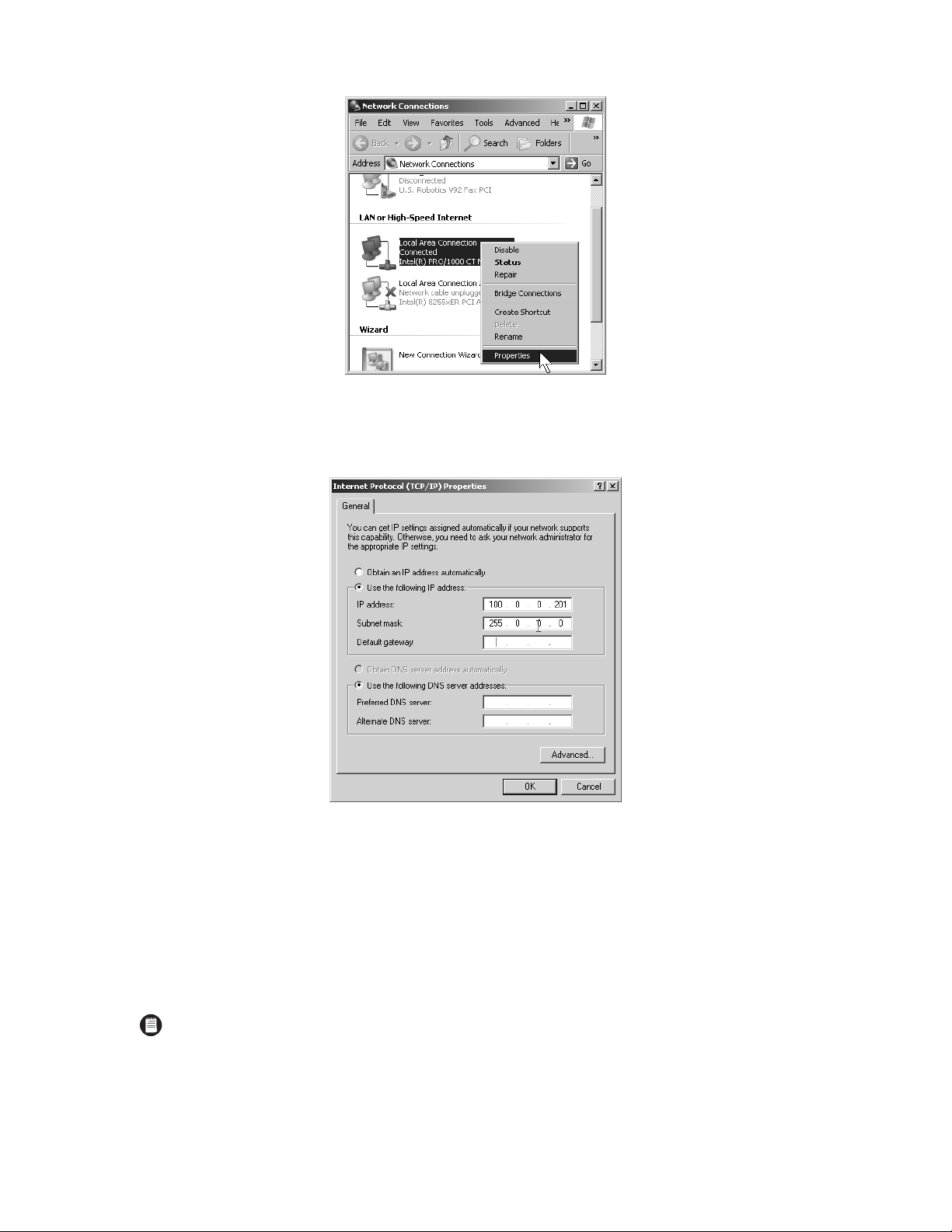
C1553M-B (4/05) 21
Figure 3. Opening the Local Area Connection Properties Dialog Box
3. In the Local Area Connection Properties dialog box, double-click the Internet Protocol (TCP/IP) listing. The Internet Protocol (TCP/IP)
Properties dialog box appears.
Figure 4. Internet Protocol (TCP/IP) Properties Dialog Box
By default, the properties are set to “Obtain an IP address automatically” and “Obtain DNS server address automatically.”
4. Click “Use the following IP address,” and then complete the following steps:
a. Enter the IP address of the VMX300(-E) workstation.
b. Enter the subnet mask address.
c. If applicable, enter the default gateway address, and the preferred and alternate DNS server addresses; otherwise, skip this step and
proceed to step 5.
5. Click OK to close the Internet Protocol (TCP/IP) Properties dialog box, and then click OK to close the Local Area Connection Properties dialog
box.
6. Close the Network Connections window by clicking the X in the upper right-hand corner of the window.
NOTE: You must assign a unique IP address to each VMX300(-E) workstation in your system.
Page 22
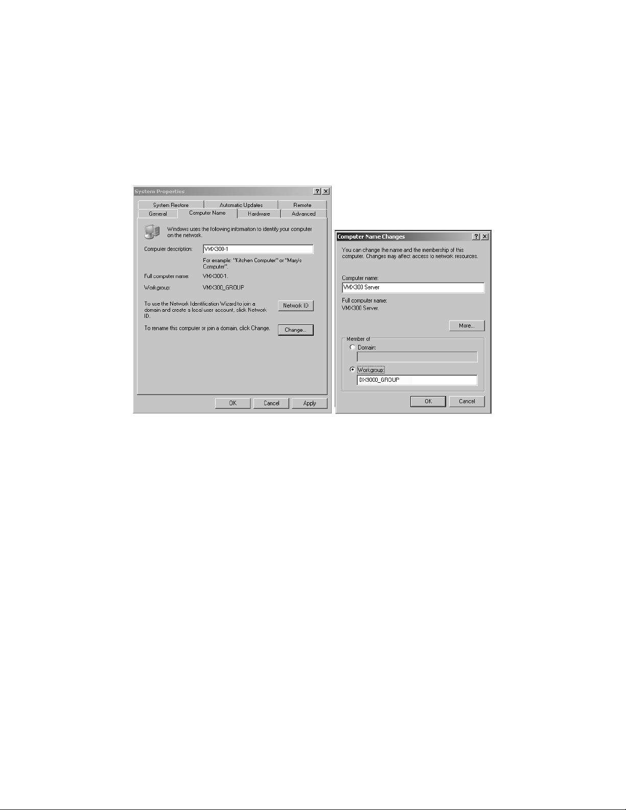
22 C1553M-B (4/05)
IDENTIFY THE VMX300(-E) WORKSTATION ON THE NETWORK
This procedure includes assigning a unique computer name to the VMX300(-E) workstation and then assigning the VMX300(-E) workstation to a
workgroup or a domain. If these steps are not applicable in your system, skip this procedure. Note that if you are using a DX9000 Series DVR in
your system, you must assign the VMX300(-E) to the appropriate DX9000 workgroup.
To identify the VMX300(-E) on the network, complete the following steps:
1. On the Windows XP desktop, right-click the My Computer icon, and then click Properties. The System Properties dialog box appears.
2. Click the Computer Name tab, and then click Change. The Computer Name Changes dialog box appears.
Figure 5. Identify the VMX300(-E) Workstation on the Network
3. In the “Computer name” field type the new name.
4. (Optional) Assign the VMX300(-E) to be a member of a workgroup or a domain:
To assign the VMX300(-E) to a workgroup enter the workgroup name in the Workgroup field.
To assign the VMX300(-E) to a domain click Domain, and then enter the domain name. Click OK, and then enter the user name and
password in the Domain Username and Password dialog box.
5. Click OK. The Computer Name Changes message appears indicating that the VMX300(-E) has been assigned to the specified workgroup or
domain.
6. Click OK. The restart message appears.
7. Click OK, close all windows, and then restart the VMX300(-E) workstation.
Page 23
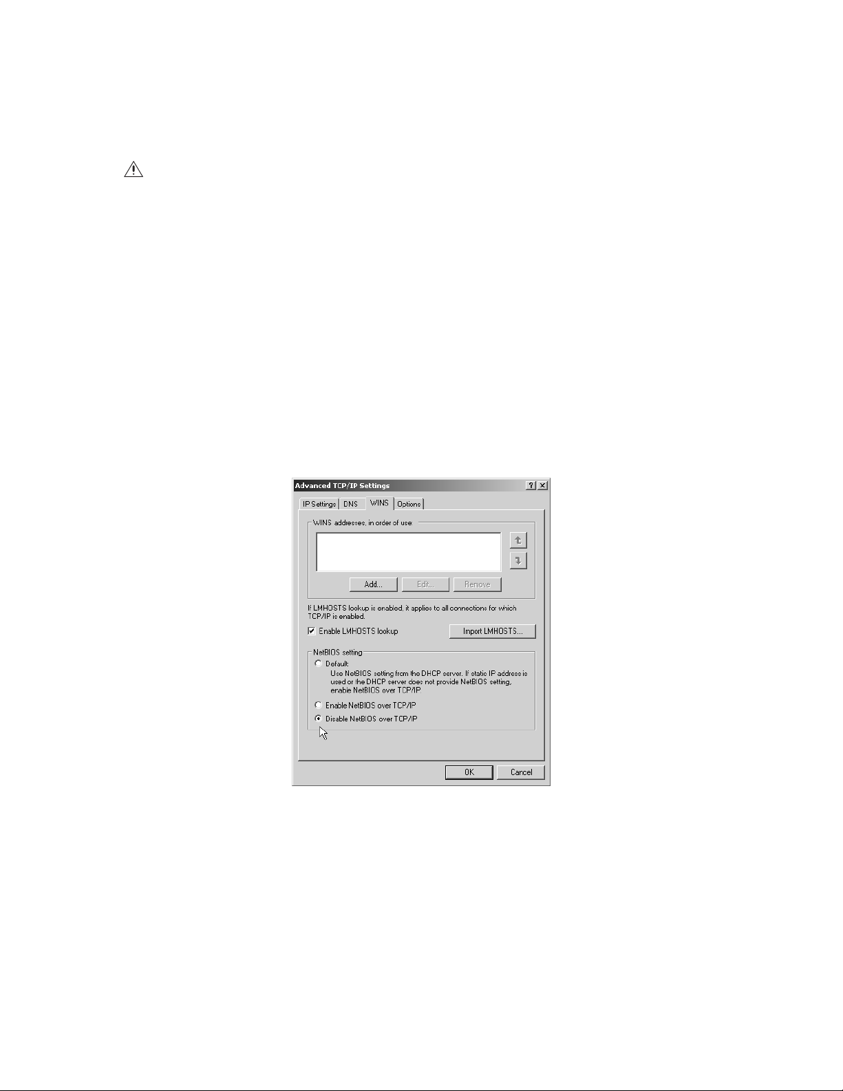
C1553M-B (4/05) 23
DISABLE NETBIOS
A workstation running the NetBIOS service on a network can be vulnerable to attack from outside sources. If you are not using a DX9000 Series
DVR, you should complete the following steps to disable the NetBIOS service in the Windows operating system. Note, however, that you should
contact your network administrator before changing any NetBIOS settings.
To disable NetBIOS, complete the following tasks; instructions are provided in the following sections:
•
Disable the NetBIOS setting in the Advanced TCP/IP Settings dialog box.
•
Disable the NetBIOS Helper in the Services window.
After completing these tasks, restart the workstation.
Disable NetBIOS in the Advanced TCP/IP Settings Dialog Box
1. Click Start > Settings > Network Connections. The Network Connections window appears.
2. Right-click Local Area Connection, and then select Properties from the pop-up menu.
3. In the Local Area Connection Properties dialog box, double-click the Internet Protocol (TCP/IP) listing. The Internet Protocol (TCP/IP)
Properties dialog box appears (refer to Figure 4).
4. Click Advanced. The Advanced TCP/IP Settings dialog box appears.
Figure 6. Advanced TCP/IP Settings Dialog Box–WINS Page
5. Click the WINS tab, and then click “Disable NetBIOS over TCP/IP.”
6. Click OK.
7. Click No in any messages regarding bindings (you do not need any bindings).
8. Click Yes in any additional messages that appear, and then click OK to close the remaining open dialog boxes.
9. Continue with the steps described in the next section to disable the NetBIOS Helper service.
CAUTION: The NetBIOS service is required for the DX9000. Do not complete this procedure if you are using a DX9000 Series DVR or if any
other applications in your system require the NetBIOS service. You should follow proper security measures to limit the network’s exposure
to potential threats when the NetBIOS service is enabled.
Page 24
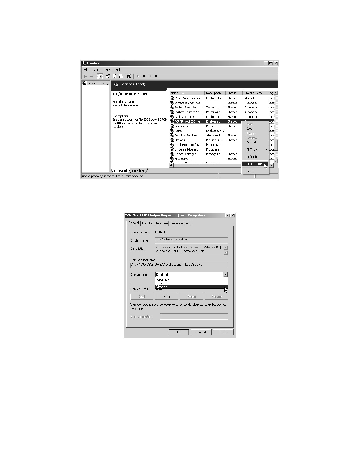
24 C1553M-B (4/05)
Disable the NetBIOS Helper Service
1. Click the Windows Start button, and then select Settings > Control Panel > Administrative Tools > Services. The Services window appears.
Figure 7. Windows Operating System Services Window
2. Right-click the service named TCP/IP NetBIOS Helper, and then click Properties. The TCP/IP NetBIOS Helper Properties dialog box appears.
Figure 8. TCP/IP NetBIOS Helper Properties Dialog Box
3. Click the down arrow in the “Startup type” drop-down box, and then click Disabled.
4. Click OK, close all windows, and then restart the VMX300(-E) workstation.
Page 25

C1553M-B (4/05) 25
Starting and Stopping the Server
The VMX300(-E) server can be launched in run mode or configuration mode. Configuration mode has a user interface that allows you to configure
any type of object, including the following objects:
•
Users
•
Maps
•
Devices
•
Scripts
•
Alarms and events
To launch the VMX300(-E) server in configuration mode, a user must have permission to configure the software. Refer to User Groups - Group
Permissions for more information.
Run mode has no user interface. When the VMX300(-E) server is in run mode, the server application is moved to the Windows system tray, where
it continues to run in the background. The server must be in run mode for clients to connect to it.
Run mode has a pop-up menu that is opened by right-clicking the VMX300(-E) icon in the Windows system tray. The menu has the options listed
in Table A.
Table A. Options for Run Mode
Save configuration: When you change the server configuration, most changes do not come into effect until after the configuration has been
saved. Only changes to device drivers and devices come into effect immediately, with the exception of a device’s local settings, which come into
effect after the configuration is saved. Refer to Device Settings - Edit a Device’s Local Settings for information on local settings.
To save the server configuration, select File > Save or exit configuration mode and say Yes when asked whether you want to save the
configuration. The server will verify that all scripts and expressions are valid before saving. Operators logged in to the VMX300(-E) client will be
momentarily interrupted while the configuration is being saved. After the interruption, operators will see the new configuration.
If one or more scripts or expressions contain errors, the server displays an error message and gives you the opportunity to make corrections.
Refer to Scripts and Expressions - Syntax Error-Checking for instructions on using the Scripts and Expressions Verification tools to make
corrections.
Scripts and expressions are also verified when you launch the server. If there are any errors, you do not have the option to launch the server in
run mode. You are automatically presented with the login dialog box for configuration mode.
MENU OPTION SECTION OF MANUAL
Configure
Configure the Server While It Is Running
Current Status
Scripts and Expressions - Variables and Values
Exit
Shut Down the Server
TIP: You can log in and out of configuration mode while the server is running. This allows you to perform administrative tasks without
preventing operators from working in the VMX300(-E) client. Refer to Configure the Server While It Is Running for instructions.
NOTE: The server will not save changes to the configuration if there are any errors. If you do not correct the errors before exiting, all the
changes you made to the configuration will be lost, except for changes to device drivers and devices.
Page 26
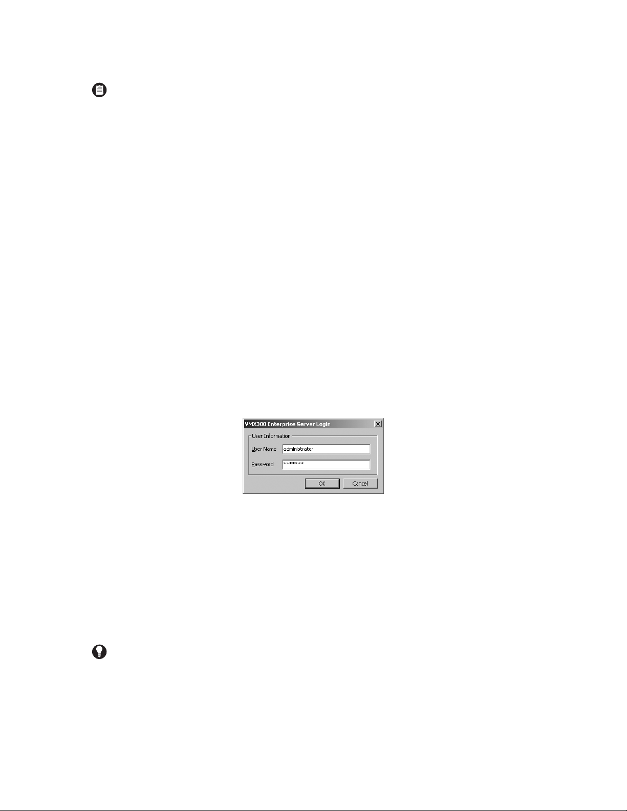
26 C1553M-B (4/05)
LAUNCH THE SERVER
To start the server:
1. Run the VMX300(-E) application from the Windows Start menu, or double-click the VMX300(-E) icon on the Windows desktop if there is
one.
If this is the first time you are launching the server, the Corrupt or Missing Database message appears because VMX300(-E) must create a
new database the first time you use it. Click Create.
If this is not the first time you are launching the server, and the Corrupt or Missing Database message appears, then the server database is
corrupted or missing. If this is the case you need to restore a backup or create a new database. Creating a new server database destroys
the existing server database if there is one. For information on restoring a backup, refer to Database Utilities.
Once a valid database is in place, the VMX300(-E) start-up screen will open. The start-up screen has a timer that counts down from
15 seconds.
2. Mode:
a. Run mode: To launch the server in run mode, click Run, or let the timer count down to zero. The VMX300(-E) icon appears in the
Windows system tray, indicating that the server is running.
b. Configuration mode: To launch the server in configuration mode, click Configure before the counter reaches zero. The Server Login
dialog box opens.
Figure 9. Server Login Dialog Box
c. Type your user name and password. If this is the first time the server has been launched, use the predefined administrator account
(user name: administrator, password: 2899100) supplied with the system.
User names are not case sensitive. For example, Administrator and ADMINISTRATOR are equivalent to administrator.
Passwords are case sensitive. For example, Password and PASSWORD are not equivalent to password.
d. Click OK. The Configuration window opens after several seconds.
Note that VMX300 synchronizes the device drivers each time you launch the server configuration. You can skip this process by clicking
Skip in the Synchronizing Drivers dialog box.
NOTES:
• If this is the first time you have launched the server, or if your base license has expired, you must enter a base license before proceed-
ing with the configuration. Click Yes when asked whether you want to enter a base license. The License Manager will open. Follow
the instructions in License Manager - Add a License.
• If the server configuration has more devices or clients than your licensing allows, possibly because an upgrade license has expired,
VMX300(-E) will warn you and present you with the login dialog box for configuration mode. If desired, log in to configuration mode
and delete devices and clients until you are within the allowable limit, or contact Pelco to obtain additional licenses.
TIP: For security reasons, it is recommended that you change the password for the built-in user administrator account the first time you
log in.
Page 27
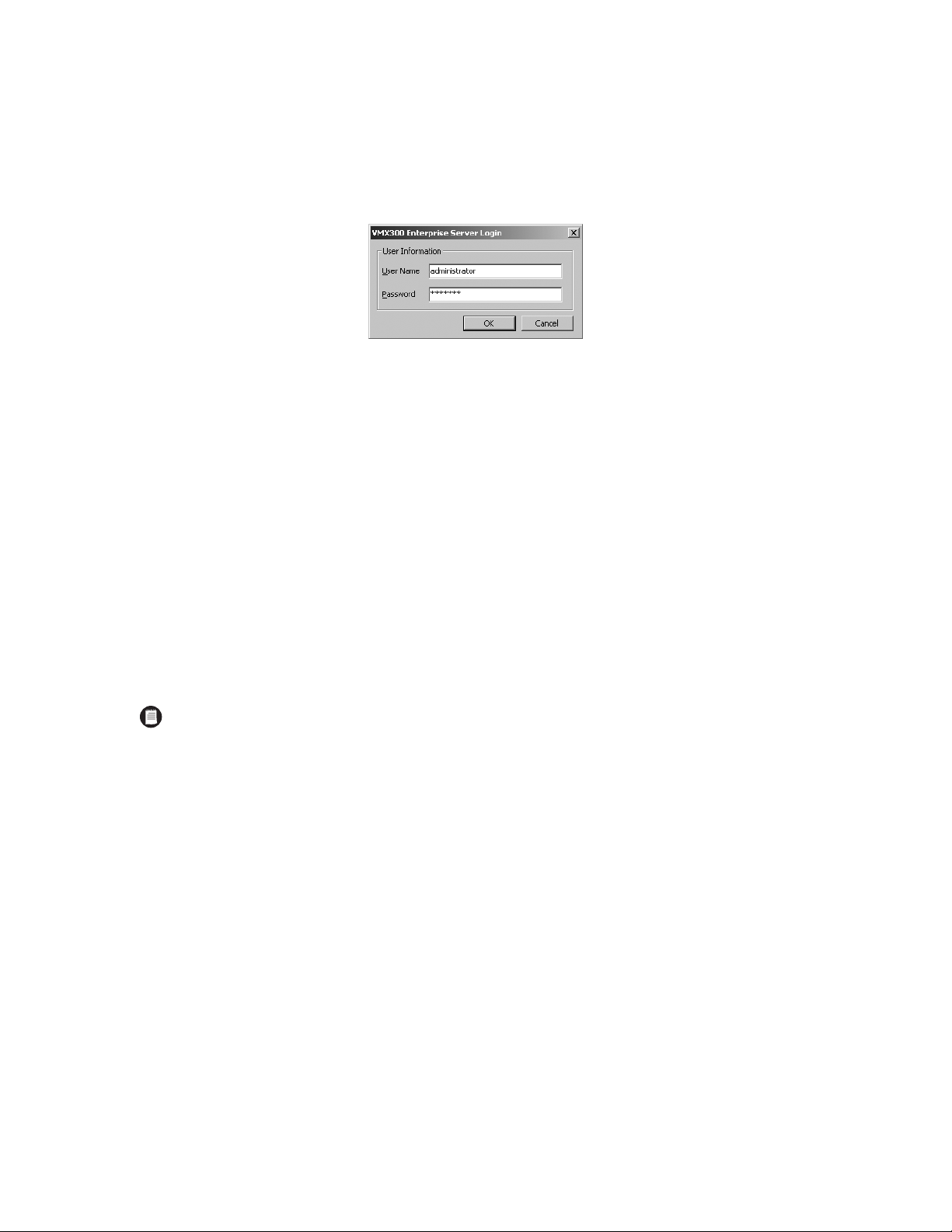
C1553M-B (4/05) 27
CONFIGURE THE SERVER WHILE IT IS RUNNING
You can log in and out of configuration mode while the server is running. This allows you to perform administrative tasks without preventing
operators from working in the VMX300(-E) client. When the server is in run mode, perform the following steps:
1. Double-click the VMX300(-E) icon in the Windows system tray, or right-click the icon and select Configure from the pop-up menu. The
Server Login dialog box opens.
Figure 10. Server Login Dialog Box
2. User name: Type your user name. User names are not case sensitive. For example, Bob and BOB are equivalent to bob.
3. Password: Type your password. Passwords are case sensitive. For example, Admin1 and ADMIN1 are not equivalent to admin1.
4. Click OK. After several seconds, the Configuration window opens.
5. Make whatever changes you want to the server configuration.
6. Save changes: If you made changes to the server configuration, select File > Save to save your changes. The server verifies your changes.
If one or more scripts or expressions contain errors, the server displays an error message and gives you the opportunity to make corrections.
Refer to Scripts and Expressions - Syntax Error-Checking for instructions on using the Scripts and Expressions Verification tools to make
corrections.
7. Exit configuration mode: Click File > Close or click the Close button at the right of the Configuration window title bar.
If you made changes to the configuration that have not been saved, the server asks whether you want to save your changes. Click Yes to
save your changes. The server verifies your changes. Make corrections as needed.
Once there are no errors, the Configuration window closes, momentarily interrupting operators logged in to the client. The server continues
to run.
LOG OUT OF CONFIGURATION MODE AND LAUNCH RUN MODE
To put the server in run mode from configuration mode:
1. Save changes: If you made changes to the server configuration, select File > Save to save your changes. The server verifies your changes.
If one or more scripts or expressions contain errors, the server displays an error message and gives you the opportunity to make corrections.
Refer to Scripts and Expressions - Syntax Error-Checking for instructions on using the Scripts and Expressions Verification tools to make
corrections.
2. Exit configuration mode: Click File > Exit and Run.
If you made changes to the configuration that have not been saved, the server asks whether you want to save your changes. Click Yes to
save your changes. The server verifies your changes. Make corrections as needed.
Once there are no errors, the Configuration window closes and the server launches. When the server is running, the VMX300(-E) icon
appears in the Windows system tray.
NOTE: You must exit server configuration mode to make changes to the configuration come into effect. The exception to this is changes to
device drivers and devices, which come into effect immediately.
Page 28
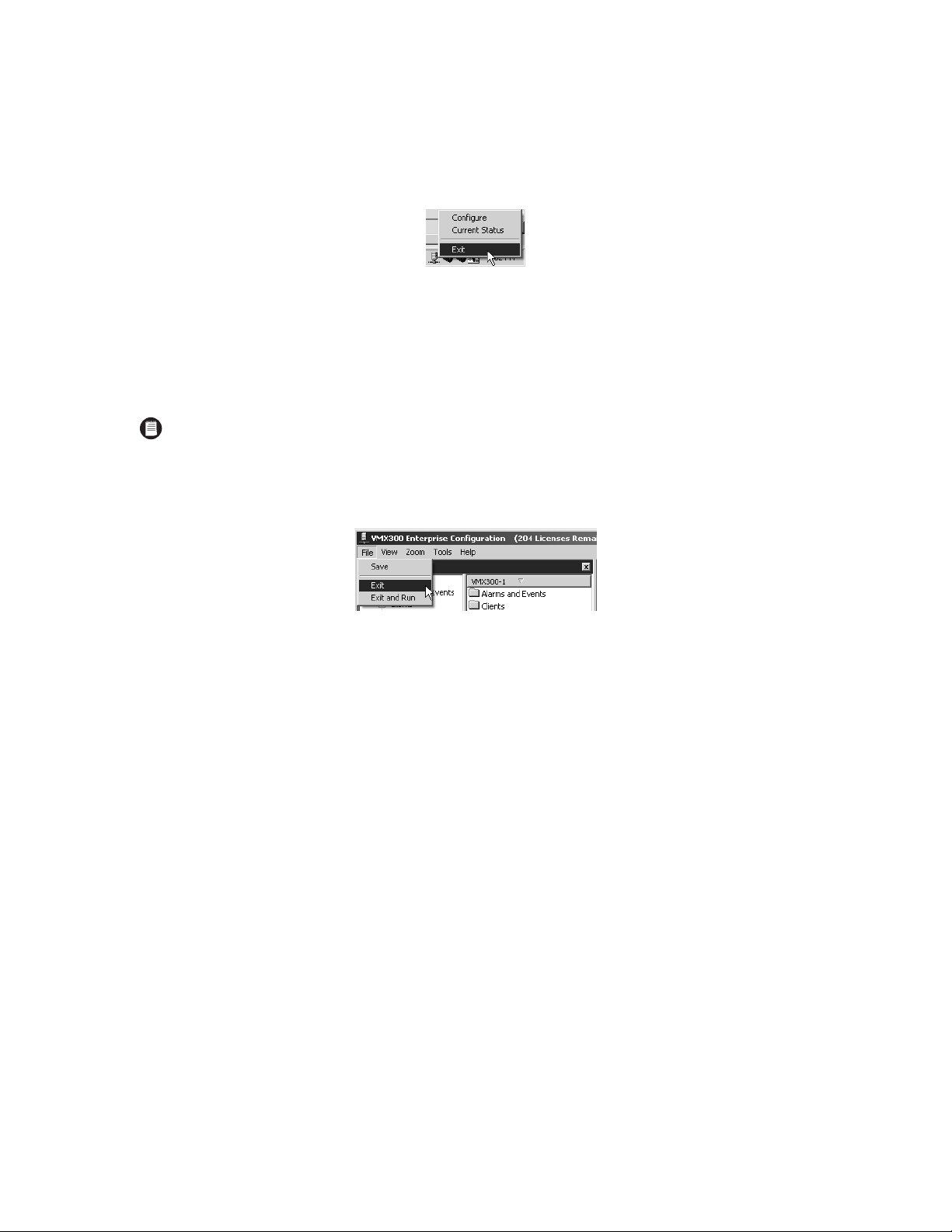
28 C1553M-B (4/05)
SHUT DOWN THE SERVER
SHUTTING DOWN WHILE IN RUN MODE
1. Right-click the VMX300 icon in the Windows system tray, and then select Exit from the pop-up menu.
Figure 11. Run Mode Pop-up Menu
2. The shutdown prompt appears.
3. Click Yes. The server shuts down.
SHUTTING DOWN WHILE IN CONFIGURATION MODE ONLY
1. If the server is in Configuration mode only, click File > Exit.
Figure 12. File Menu
2. If the server configuration has not changed, the server shuts down immediately.
If you made any changes to the configuration, the Save Changes prompt appears. Click Yes to save changes.
If any scripts or expressions contain errors, the Script and Expression Verification window appears. Use this window to correct the errors
(refer to Syntax Error-Checking in the Scripts and Expressions section for instructions), and then click OK. The Script and Expression
Verification window closes and the server shuts down.
NOTE: If the server is in both Run mode and Configuration mode, you must shut it down through Run mode. You cannot shut down the
server from Configuration mode when the server is running. Closing the configuration when the server is in Run mode leaves the server
running.
Page 29
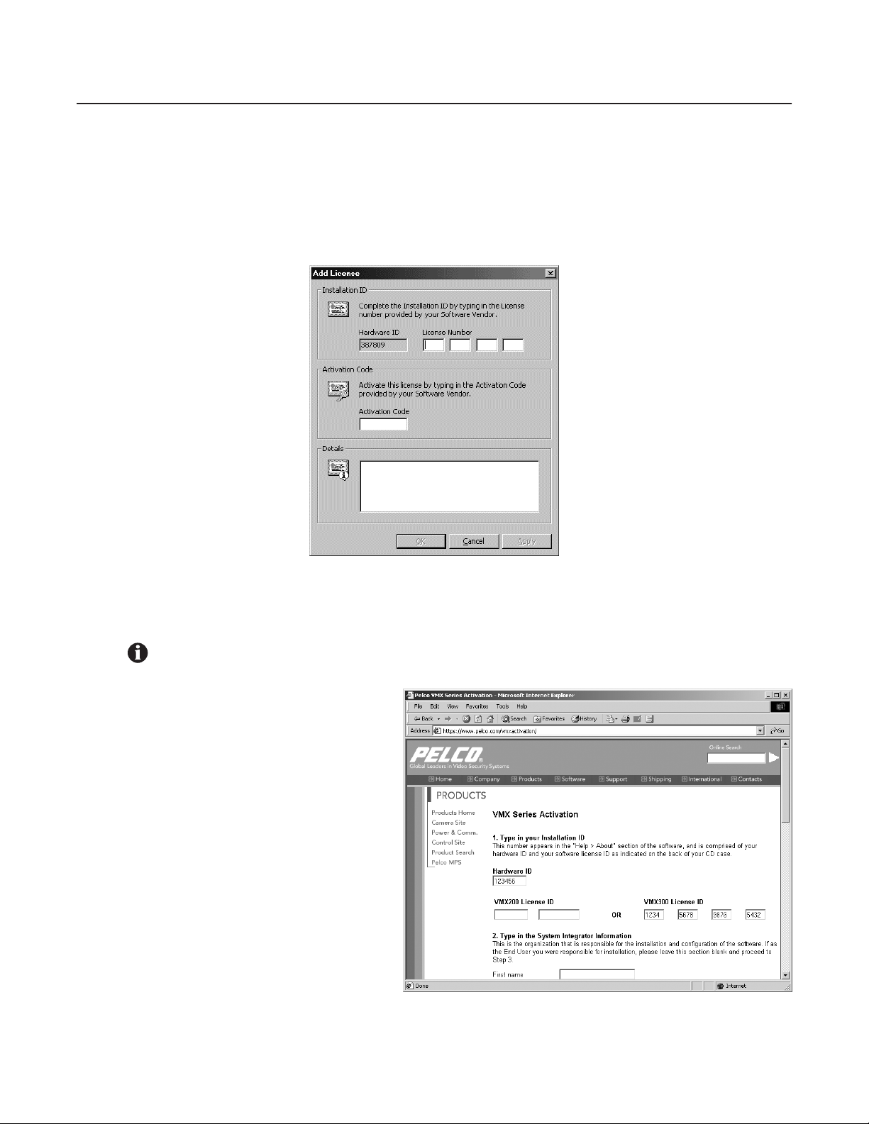
C1553M-B (4/05) 29
License Manager
License Manager provides a convenient means of managing your software licenses. Each server in your system must have a valid base license to
run VMX300(-E). If no valid base license is registered, you will not be able to launch the server without first adding a license.
ADD A LICENSE
1. If the server has prompted you to enter a license, click Yes. Otherwise, open the License Manager by clicking Tools > License Manager.
Then click Add in the License Manager dialog box. The Add License dialog box opens.
Figure 13. License ID
2. Enter your license ID in the Add License dialog box. The base license ID and any additional license IDs (each ID is a four-part number) are
provided on the VMX300(-E) Licenses sheet. The hardware ID is entered by Pelco at the factory.
3. Obtain your activation code.
a. Open your Internet browser and go to the
VMX Series Activation page at
Pelco.com. http://www.pelco.com/
vmxactivation
b. Enter your hardware ID and license ID,
and then complete the remaining fields.
c. Click Activate. A confirmation screen
appears, containing your activation code.
OR
Call Pelco Technical Support:
1-800-289-9100 or
1-559-292-1981
IMPORTANT: Once you have entered your License ID, you must obtain your activation code (step 3) and then enter it (step 4) within 45
days.
Figure 14. Hardware ID and License ID
Page 30
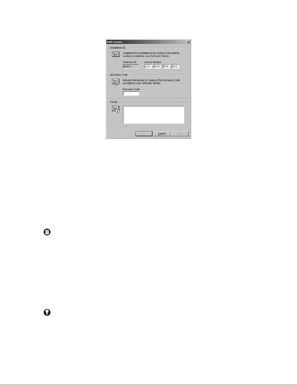
30 C1553M-B (4/05)
4. Enter your activation code in the Add License dialog box.
Figure 15. Activation Code
5. Click Apply.
If you purchased additional license IDs, repeat steps 1-4 for each license ID.
Note that licenses are applied as follows:
VMX300 Client Application Five licenses for each additional client (licenses for the first client application are covered by the base
license)
VMX300-E Client Application Ten licenses for each additional client (licenses for the first client application are covered by the base
license)
Cameras One license for each camera
6. Click Close.
DELETE A LICENSE
If you delete the base license, the server will ask you if you want to enter a new license. If you select No, the server will shut down. If you select
Yes, the Add License dialog box will open. Refer to Add a License for instructions on entering licensing information.
1. In the Licenses area of License Manager, select the license you want to delete and click Remove. The server prompts for confirmation.
2. If you are sure you want to delete the license, click Yes. The license name disappears from the Licenses list and details for that license are
removed from the summary.
NOTE: To refer to the installation ID or activation code at a later time, complete the following steps:
• Select Tools > License Manager from the menu bar. The License Manager dialog box appears.
• Click your license, and then click Properties. The License Properties dialog box appears.
TIP: Delete any licenses that have expired, as they serve no purpose. They cannot be reactivated.
Page 31

C1553M-B (4/05) 31
Starting and Stopping Device Drivers
START A DEVICE DRIVER
Start each device driver needed to control the devices in your system. You can start the drivers before you start the VMX300(-E) server, or after.
When you start a device driver, you have the choice of running it as an executable or as a service. If you ever have to restart a driver that is run
as an executable, you will have to follow the steps outlined here. To restart a driver that is run as a service, restart the computer the driver is
installed on, or start the driver through the Windows Control Panel Administrative Tools.
To start a device driver:
1. Run the device driver application from the Windows Start menu, or double-click the driver icon if there is one on the Windows desktop.
If this is the first time you are launching the device driver, the Corrupt or Missing Database message appears because VMX300(-E) must
create a new database the first time you use it. Click Create.
If this is not the first time you are launching the device driver, and the Corrupt or Missing Database message appears, then the driver database is corrupted or missing. If this is the case you will need to either restore a backup or create a new database. Creating a new database
destroys the existing database if there is one. For information on restoring a backup, refer to Database Utilities.
Figure 16. Create or Restore Database Dialog Box
Once a valid database is in place, the Configure Driver dialog box opens.
Figure 17. Configure Driver Dialog Box
2. If the driver is currently installed to run as a service and you want to run it as an executable, click “Remove the driver as a service,” then
click OK. Repeat step 1 to re-open the Configure Driver dialog box.
3. Local network adapter: Select the IP address of the computer the driver is installed on from the drop-down list.
4. Listening port: The listening port is the port the device driver uses to receive commands from the server.
If you have not yet added the device driver to the server configuration, use the default port number provided, or type in a port number
between 2 000 and 10 000 that has not been assigned to another driver. Use this port number as the Listening Port when you add the device
driver to the server configuration.
If the device driver has previously been added to the server configuration, select the driver’s listening port from the drop-down list. The listening port is the port that was specified when the driver was added to the server configuration. To find out the listening port, log in to configuration mode. The port is displayed beside the driver in the Object Browser.
TIP: If you run a device driver as a service, you can set the driver to restart automatically in the event of failure. Once the driver is running
as a service, go into Windows Control Panel Administrative Tools, open the driver service, and set the restart options on the Recovery tab.
Page 32

32 C1553M-B (4/05)
5. Mode:
a. Executable: To run the device driver as an executable, click “Start the driver as an executable.”
b. Service: To run the device driver as a service, click “Install the driver as a service.”
6. Some device drivers support additional options. For more information on a particular driver’s options, refer to Device Drivers for that driver.
7. Click OK. The Configure Driver dialog box closes. If you are running the driver as a service, start the driver through the Windows Control
Panel Administrative Tools, or restart the computer the driver is installed on. An icon representing the driver appears in the Windows
system tray, indicating that the driver is running.
SHUT DOWN A DEVICE DRIVER
1. Right-click the driver icon in the Windows system tray and select Exit from the pop-up menu. You are prompted to confirm.
2. If you are sure you want to shut down the driver, click Yes. The driver shuts down.
DX8000 NOTE: The option to run the DX8000 driver as a service is not available at this time. When starting the DX8000 driver, you must
click “Start the driver as an executable.”
TIP: To check whether a device driver is running, log in to configuration mode, edit the device driver, and click Check Now. While the server
is checking, the buttons in the dialog box are unavailable. If the server succeeds in finding a driver, the buttons become available again.
If no driver is found, the server displays a warning message. Refer to Edit a Device Driver’s Properties for more information.
NOTE: If the device driver is running as a service, you can also shut it down through the Windows Control Panel Administrative Tools.
Page 33

C1553M-B (4/05) 33
Clients, Custom Windows, and Canvases
VMX300(-E) provides tools to define custom windows that are viewable through the client. Custom windows are used for the following functions:
• Viewing live and archived video
• Displaying maps
• Displaying an Internet browser
• Connecting to a remote computer
In order for an operator to be able to connect to a server and use a custom window in the client, you must do the following:
• Add the operator’s workstation to the server configuration as described in Add a New Client.
• Create a custom window for the new client as described in Add a New Custom Window.
• If the operator is going to view video in the window, add one or more canvases to the window as described in Add a New Canvas (General),
and, for analog canvases, specify the connections between devices.
Canvases are only required if the window will be used to view video. Canvases define the video display technology available to that client, and
can include both analog and digital (IP-based) technologies. Refer to Canvases for more information.
Connections map out how video equipment is physically connected. Refer to Connections for more information.
CLIENTS
Adding an operator’s computer to the server configuration allows that workstation to connect to the server. When you add a client to the server
configuration, you can
• Supply a default workspace for the client
• Make custom windows available on the client
Refer to Workspaces for information on creating a default workspace. Refer to Custom Windows for information on configuring custom windows.
WORKSPACES
Workspaces control the appearance of the VMX300(-E) client. In particular, they control which windows are displayed, and their size, position,
and content.
You can create a default workspace that loads automatically on a specified client when an operator logs in to that client. Operators with
permission to work with workspaces can override the default by setting preferences to load a workspace of their choosing automatically, or by
explicitly opening a workspace once they have logged in. Refer to User Groups for information on workspace permissions.
To create a workspace, you must log in to the VMX300(-E) client under a user group that allows you to work with workspaces, and you must be
connected to your home server. Refer to Configuring Servers in the VMX300(-E) Client Operation Manual for information on selecting a home
server.
Once logged in, you can change the appearance of the display either by using standard Windows techniques for resizing and repositioning
windows, or by editing the workspace. When the display is adjusted as you want it, save the workspace. Refer to Workspaces in the VMX300(-E)
Client Operation Manual for information on editing and saving a workspace.
To use the workspace as the default workspace for a client, log in to the server in configuration mode and edit the client as described in Edit a
Client’s Properties
TIP: If you are configuring a newly-installed server and find you have many clients to create with a similar configuration, you can do it very
quickly as follows: Add one client with the desired windows and canvases. Use Copy and Paste Many to create multiple copies of the
client. Each copy of the client will have the identical windows and canvases defined for it. Then edit the copies one at a time to customize
them as needed. This technique is particularly useful for clients that will have access to the same custom windows. Refer to Pop-Up Menus
in the Appendix for detailed instructions on using Copy and Paste Many.
Page 34

34 C1553M-B (4/05)
ADD A NEW CLIENT
1. Navigate the Object Browser to [project name] > Clients. Double-click <Add New Client> in the right pane, or right-click Clients in the left
pane and select Add New from the pop-up menu. The Add New Client dialog box opens.
Figure 18. Add New Client Dialog Box
2. Computer name: Type in the name of the computer you want to add as a client of the VMX300(-E) server, or click Browse to select from a
list of computers visible on the network. The computer name you enter here must be identical to the computer name listed in Windows
Control Panel System on the computer you want to add. Use the computer name to refer to the client in scripts and expressions. For a list of
client properties that can be scripted, refer to Scripts and Expressions - Properties of Objects.
3. Default workspace: If you want the server to supply a default workspace to the client you are adding, type in the pathname of the
workspace file you want to load, or Browse to select the desired file. VMX300(-E) loads the default workspace for any operator whose user
preferences are set to “Use the workspace supplied by the server.” Refer to Workspaces for information on creating workspaces.
4. Click OK. The Add New Client dialog box closes and the new client is added. The name of the new client appears in the Object Browser.
EDIT A CLIENT’S PROPERTIES
1. Navigate the Object Browser to [project name] > Clients. In either pane, right-click the client whose properties you want to change and
select Edit from the pop-up menu. The Edit Client Properties dialog box opens.
Figure 19. Edit Client Properties Dialog Box
2. Change properties of the client as desired. Refer to Add a New Client for information on specific properties.
3. Click OK. The Edit Client Properties dialog box closes.
Page 35

C1553M-B (4/05) 35
DELETE A CLIENT
1. Navigate the Object Browser to [project name] > Clients. In either pane, right-click the client you want to delete and select Delete from the
pop-up menu. The Confirm dialog box opens.
2. If you are sure you want to delete the client, click Yes.The selected client is deleted and the Confirm dialog box closes. The deleted client
disappears from the Object Browser.
CUSTOM WINDOWS
Custom windows are viewed through the VMX300(-E) client. They are used for the following functions:
• Viewing live and archived video
• Displaying maps
• Displaying an Internet browser
• Connecting to a remote computer
Any window that will be used to view video must have one or more canvases defined for it that reflect the video display technologies available to
the client. Refer to Canvases for more information.
You can configure custom windows so that more than one client can view a particular window, simply by giving the window the same name and
script tag on each client. Any action affecting the window that is executed automatically by a script will affect that window on every client that
runs the script. Anything done manually by an operator, such as dragging a camera to a window, will not affect any other operator’s window.
For example, suppose you want to alert several different operators when an exit door is opened. First, create a recipient group and make the
operators members of the group. Now create an alarm/event category that simultaneously sends notification to each member of that recipient
group. Finally, define an alarm belonging to that category with an On Event script that loads live video of the exit area into a particular window
that is defined on each operator’s client. When the alarm is triggered, the script will automatically load the video in the window of each recipient
operator who is logged in at the time.
HOW MANY CUSTOM WINDOWS TO CONFIGURE
The number of custom windows that you need to configure will vary based on your specific system parameters. In general, configure as many
custom windows as you want the operator using this client to view at any one time.
For example, a total of nine custom windows are required for an operator to view the following types of content at one time:
• A map (operators can view maps in custom windows as well as in the viewport)
• A web page
• Three analog video streams
• Four digital video streams
Note, however, that your specific system parameters will limit the number of digital video streams that an operator can view at any one time.
Refer to Table B in the How to Choose the Video Stream Settings for Your Configuration section for an overview of the maximum number of
streams recommended for specific digital settings.
NOTES:
• Deleting a client is irreversible. If you delete a client and then change your mind, you must add it back as described in Add a New
Client.
• Deleting a client does not affect workspace files.
TIP: You can copy a custom window from one client to another using Copy and Paste. Refer to Pop-Up Menus in the Appendix for detailed
instructions on using Copy and Paste.
Page 36

36 C1553M-B (4/05)
ADD A NEW CUSTOM WINDOW
To add a new custom window to a particular client:
1. Navigate the Object Browser to [project name] > Clients > [client name] > Windows. Double-click <Add New Window> in the right pane, or
right-click Windows in the left pane and select Add New from the pop-up menu. The Add New Window dialog box opens.
Figure 20. Add New Window Dialog Box
2. Name: Type in a descriptive name for the custom window you want to add. A particular client cannot have two windows with the same
name. However, different clients can have windows with the same name. Window names are at most 50 characters long and can include
any letter, digit or special character, with the exception of single and double quotation marks. Window names are not case sensitive.
A tag resembling the window name appears in the Script Tag box. If the window name contains special characters, they are omitted from
the tag. Spaces are replaced with underscores. Leading digits are removed.
3. Script tag: If you do not want to use the script tag provided by the server, type in a tag. Script tags are at most 50 characters long. They
can include any letter, digit or the underscore character, but cannot begin with a digit. They cannot contain spaces or special characters.
Tags are not case sensitive. Use the script tag to refer to the custom window in scripts. For a list of window properties that can be scripted,
refer to Scripts and Expressions - Properties of Objects.
4. Click OK. The Add New Window dialog box closes and the new window is added. The name and script tag of the new window appear in
the Object Browser. When logged in to the client for which the window is defined, an operator with permission to edit workspaces will see
the window listed in the Edit Workspace dialog box.
EDIT A CUSTOM WINDOW
To change the properties of an existing custom window:
1. Navigate the Object Browser to [project name] > Clients > [client name] > Windows. In either pane, right-click the window you want to
change and select Edit from the pop-up menu. The Edit Window Properties dialog box opens.
Figure 21. Edit Window Properties Dialog Box
2. Change properties of the window as desired. Refer to Add a New Custom Window for information on specific properties.
3. Click OK. The Edit Window Properties dialog box closes.
NOTE: If the same custom window will be viewed by more than one client, it must have the same name and script tag for every client.
NOTE: If you change the script tag for a custom window, any script that refers to the window will contain an error. To correct the error,
update the scripts so they use the window’s new script tag. Refer to Scripts and Expressions for more information.
Page 37

C1553M-B (4/05) 37
DELETE A CUSTOM WINDOW
Deleting a custom window is irreversible. If you delete a custom window and then change your mind, you must add a new custom window. Also
note that if you delete a custom window, any script that refers to the custom window will contain an error.
1. Navigate the Object Browser to [project name] > Clients > [client name] > Windows. In either pane, right-click the window you want to
delete and select Delete from the pop-up menu. The Confirm dialog box opens.
2. If you are sure you want to delete the window, click Yes. The selected window is deleted and the Confirm dialog box closes. The deleted
window disappears from the Object Browser.
CANVASES
Any custom window that will be used to display video must have at least one canvas defined for it. Canvases specify the video display
technology available to the client the custom window is configured for. This can include both analog and digital (IP) technologies. VMX300(-E)
supports two analog video display technologies:
• Quad Video Display
• Video for Windows
To use either of these analog technologies, the client computer must have an appropriate video card installed in it.
If you add more than one canvas to a custom window, VMX300(-E) will have a choice of which video display technology to employ when an
operator views video in that window. VMX300(-E) makes its choice based on the order the canvases are listed in the Object Browser. Refer to Re-
Order a Window’s Canvases for more information.
ADD A NEW CANVAS (GENERAL)
To add a new canvas to a custom window:
1. Navigate the Object Browser to [project name] > Clients > [client name] > Windows > [window name] > Canvases. Double-click <Add New
Canvas> in the right pane, or right-click Canvases in the left pane and select Add New from the pop-up menu. The Add New Canvas dialog
box opens.
Figure 22. Add New Canvas Dialog Box
2. Select the canvas you want to add from the drop-down list.
3. Settings: If the Settings button is available, click Settings to configure the canvas settings. Some canvases do not have settings. If there
are no settings, go to step 6.
4. General tab: For Video for Windows and Quad Video Display canvases, the settings available on the General tab assign hardware to the
canvas, and are hardware dependent. Instructions for configuring Video for Windows and Quad Video Display settings follow.
a. Card number: Use the default card number setting.
TIP: To provide maximum flexibility for a client, add as many canvases as you can: one for each analog video card in the client, and one for
each video encoder configured on the server.
Page 38

38 C1553M-B (4/05)
b. Video input number (Quad Video Display cards only): Select the video input number for the canvas you are configuring from the
drop-down list. Click OK to close the dialog box.
Figure 23. General Setting for Quad Video Display
5. Advanced tab: For all types of canvas, the canvas settings Advanced tab allows you to configure the image quality for image capture files,
including both automatic FTP image capture and image capture initiated by an operator using the Capture button. You only need to
configure the settings on the Advanced tab if the canvas is going to be used to capture images.
a. Picture quality: Use the slider to set the quality of the images you want captured from this canvas. Lower the quality to reduce the
file size of captured images.
b. Stretch picture: Select Stretch picture if you want to change the dimensions of captured images. The dimensions are given in pixels.
It is recommended that you only reduce the size, not increase it, since increasing the picture dimensions will make the picture look
grainy. To prevent distortion, reduce the width and height by the same proportion. Reduce the dimensions to 80 x 60 for thumbnails.
Figure 24. Advanced Settings
6. Click OK. The Add New Canvas dialog box closes and the new canvas is added. The name of the canvas appears in the Object Browser.
Page 39

C1553M-B (4/05) 39
ADD A NEW CANVAS (PELCONET)
Any custom window that is used to display video encoded by a PelcoNet encoder or encoder/decoder must have a PelcoNet MPEG Series canvas
defined for it. Windows used to display analog video that is decoded by a PelcoNet device do not require a PelcoNet MPEG Series canvas.
1. Navigate the Object Browser tree to [project name] > Clients > [client name] > Windows > [window name] > Canvases for the window that
will be used to display video encoded by a PelcoNet encoder or encoder/decoder.
2. Double-click <Add New Canvas>. The Add New Canvas dialog box appears.
Figure 25. Add a PelcoNet Canvas
3. Select PelcoNet MPEG Series from the drop-down box, and then click Settings. The Canvas Settings dialog box appears.
Figure 26. General PelcoNet Canvas Settings
The Selected Compatibilities field lists the types of video signal that the VMX300(-E) video window can display. By default, the window can
display all types of video signal. If you move a signal from the Selected Compatibilities field to the Available Compatibilities field, the
VMX300(-E) video window will not display those types of signals.
A VMX300(-E) video window can display the following types of signals:
• MPEG-4: PelcoNet encoders and encoder/decoders support this signal type. For information on configuring PelcoNet 4001A encoder/
decoders for this signal type, refer to Devices. For PelcoNet 3xx encoders, the MPEG-4 signal type corresponds to Stream 1, configured as
described in the Devices section.
• MPEG-2: PelcoNet 4001A encoder/decoders support this signal type. Refer to Devices for information on configuring the encoder for
MPEG-2 streaming.
• Internal Storage: This is the video signal from a PelcoNet device’s built-in recorder. This signal type applies to any PelcoNet NET350
encoder that has integral recording capability selected. Refer to Devices for instructions on configuring integral recording capability.
• MPEG-4 Secondary: PelcoNet 3xx encoders support this signal type. The MPEG-4 Secondary signal type corresponds to Stream 2,
configured as described in the Devices section.
• NVR300: The video signal from an NVR300. This signal type applies to PelcoNet encoders and encoder/decoders that have been configured
to have their streams recorded by an NVR300. Refer to Devices for more information.
Page 40

40 C1553M-B (4/05)
Change the List of Selected Signal Types
To change the list of selected signal types, you can do any of the following operations:
• Click the signal type, and then click remove; the signal type appears in the Available Compatibilities list.
• To select multiple signal types, press the Ctrl key while clicking signal types.
• To remove all signal types, click Remove All.
• To move a signal type from the Available Compatibilities list to the Selected Compatibilities list, click the signal type, and then click Add;
the signal type appears in the Selected Compatibilities list.
• To move all signal types from the Available Compatibilities list to the Selected Compatibilities list, click Add All.
Reorder the List of Selected Signal Types
VMX300(-E) attempts to display signal types in the order they appear in the Selected Compatibilities list. You can sort the list in the order you
want VMX300(-E) to try signal types. To move a signal type higher in the list, click the signal type, and then click Move Up. To move a signal type
lower in the list, click the signal type, and then click Move Down.
Refer to the Clients, Custom Windows, and Canvases section for additional information on adding a canvas.
Configure Image Quality of Captured Images
1.Click the Advanced tab on the PelcoNet Canvas Settings dialog box.
Figure 27. Advanced PelcoNet Canvas Settings
2. Configure the image quality settings as desired.
Page 41

C1553M-B (4/05) 41
ADD A NEW CANVAS (DX8000 OR DX9000 DVR)
Any custom window that is used to display video from a DX8000 or DX9000 DVR must have a DVR canvas defined for it.
1. Navigate the Object Browser tree to [project name] > Clients > [client name] > Windows > [window name] > Canvases for the window that
will be used to display video from a DVR.
2. Double-click <Add New Canvas>. The Add New Canvas dialog box appears.
Figure 28. Add a DVR Canvas
3. Select the appropriate DVR (either the DX8000 or the DX9000) from the drop-down box, and then click OK.
EDIT A CANVAS
To edit an existing canvas:
1. Navigate the Object Browser to [project name] > Clients > [client name] > Windows [window name] > Canvases. In the right pane, doubleclick the canvas you want to edit, or right-click the canvas and select Edit from the pop-up menu. The Edit Canvas Properties dialog box
opens.
Figure 29. Edit Canvas Properties Dialog Box
2. Change properties of the window as desired. Refer to Add a New Canvas (General) for information on specific properties.
3. Click OK. The Edit Canvas Properties dialog box closes.
RE-ORDER A WINDOW’S CANVASES
If you add more than one canvas to a custom window, VMX300(-E) will have a choice of which video display technology to employ when an
operator views video in that window. VMX300(-E) makes its choice based on how the canvases are ordered in the Object Browser. The server
tries the canvas at the top of the list first, then, if it is not available, the second canvas in the list, and so on.
You can re-order the canvases for a custom window using the Move Up and Move Down options.
To change the order of a window’s canvases, navigate the Object Browser to [project name] > Clients [client name] > Windows > [window name]
> Canvases. In the right pane, right-click the canvas you want to move and select Move Up or Move Down from the pop-up menu. The canvas
moves up or down one position.
DELETE A CANVAS
Deleting a canvas is irreversible. If you delete a canvas and then change your mind, you must add a new canvas.
1. Navigate the Object Browser to [project name] > Clients > [client name] > Windows > [window name] > Canvases. In the right pane, rightclick the canvas you want to delete and select Delete from the pop-up menu. The Confirm dialog box opens.
2. If you are sure you want to delete the canvas, click Yes. The selected canvas is deleted and the Confirm dialog box closes. The deleted
canvas disappears from the Object Browser. The window is no longer able to display video of the type supported by the deleted canvas.
Page 42

42 C1553M-B (4/05)
Device Drivers
VMX300(-E) uses device drivers to control and manage devices. Each device driver controls a particular type of equipment, such as surveillance
camera, video recorder, or any other type of device.
There are several steps involved in configuring device drivers on the VMX300(-E) server:
1. Launch the device driver. Refer to Starting and Stopping Device Drivers - Start a Device Driver.
2. Add the device driver to the server configuration as described in Add a New Device Driver.
ADD A NEW DEVICE DRIVER
To add a new device driver to the VMX300(-E) server:
1. Navigate the Object Browser to [project name] > Device Drivers. Double-click <Add New Driver> in the right pane, or right-click Device
Drivers in the left pane and select Add New from the pop-up menu. The Add New Driver dialog box opens.
Figure 30. Add New Driver Dialog Box
2. Select the device driver you want to add using one of the following methods:
a. Browse local: To browse the server workstation for running drivers, click Browse Local. The Browse Drivers dialog box opens.
Figure 31. Browse Local Drivers Dialog Box
The Browse Drivers dialog box lists all device drivers running on the server workstation. Select the driver you want to add and click
OK to close the Browse Drivers dialog box. The driver name, IP address, and listening port appear in their respective boxes.
NOTES:
• To add a device driver to the VMX300(-E) server, the driver must be running on the network. Once you have added a device driver to
the server configuration, you can add devices of that type.
• Changes to device drivers, such as adding a new driver to the server configuration, come into effect immediately. You cannot discard
your changes by exiting configuration mode without saving.
Page 43

C1553M-B (4/05) 43
b. Browse all: To browse the network for running drivers, click Browse All. The Browse Drivers dialog box opens.
Figure 32. Browse All Drivers Dialog Box
The Browse Drivers dialog box lists all device drivers running at network locations visible to the server you are configuring. Select the
driver you want to add and click OK to close the Browse Drivers dialog box. The driver name, IP address, and listening port will appear
in their respective boxes.
c. Add driver manually: If you know the IP address and port number of the driver you want to add, you can add the driver by typing the
address and port directly, without browsing drivers.
(1) Driver IP address: By default, the server’s IP address is entered in the Driver IP Address box. If the device driver is not installed
on the server, type the IP address of the computer the driver is installed on.
(2) Listening port: The listening port is the port the device driver uses to receive commands from the server. Type in the listening
port for the device driver you want to add. This is the port that was entered in the Configure Driver dialog box when the device
driver was launched. To find out the listening port, position the pointer over the driver icon in the Windows system tray of the
computer the driver is installed on.
(3) Check now: If you want the server to verify that a device driver is running at the specified IP address and port number, click
Check Now. While the server is checking, the dialog box’s buttons are unavailable. If the server succeeds in finding a driver, the
buttons become available again. If no driver is found, the server displays a warning message.
3. Click Add. The Add New Driver dialog box closes and the new driver appears in the Object Browser, with the IP address and port number
beside the driver name. If the driver has previously been configured, its devices also appear in the Object Browser. If you are adding a
remote server driver, the remote server’s alarms and events appear in the Object Browser as read properties of the server, and the remote
server’s devices appear as sources.
AUTODISCOVER DEVICE DRIVERS
The Autodiscover All Drivers function locates all drivers that are running on the local area network (LAN). To add a driver that is running on a
wide area network (WAN), use the Add New Driver option.
Note that changes to device drivers, such as autodiscovering drivers, come into effect immediately. You cannot discard your changes by exiting
configuration mode without saving.
1. Navigate the Object Browser to [project name] > Device Drivers. In the right pane, double-click <Autodiscover All Drivers>. The server
warns you that autodiscovering all device drivers will add to or update the currently configured drivers.
TIP: The easiest way to add a remote server driver is to Browse All and select the desired driver. Refer to Server Ties and Alarms and
Events - Access Alarms and Events Defined on Another Server for information on remote server drivers.
NOTE: In order for the VMX300(-E) system to locate a device driver automatically, the driver must be installed at a network location that is
visible to the VMX300(-E) server. If you know the IP address and port number of a driver that was not located, use the Add New Driver
option.
Page 44

44 C1553M-B (4/05)
Figure 33. Autodiscover Warning
2. If you are sure you want to proceed, click Yes. The server adds the drivers it finds to the server configuration. The drivers appear in the
Object Browser.
EDIT A DEVICE DRIVER’S PROPERTIES
You can change the IP address and port number of a device driver, but not the driver’s name.
To change the properties of an existing device driver:
1. Navigate the Object Browser to [project name] > Device Drivers. Right-click the driver you want to edit and select Edit from the pop-up
menu. The Edit Driver Properties dialog box opens.
Figure 34. Edit Driver Properties Dialog Box
2. Edit the properties as desired. Refer to Add a New Device Driver for more information.
3. Click Synchronize. The Edit Driver Properties dialog box closes.
DELETE A DEVICE DRIVER
1. Navigate the Object Browser to [project name] > Device Drivers. In either pane, right-click the driver you want to delete and select Delete
from the pop-up menu. The Confirm dialog box opens.
2. If you are sure you want to delete the device driver, click Yes. The selected driver is deleted and the Confirm dialog box closes. All the
driver’s devices are deleted and their icons removed from maps.
NOTE: Changes to device drivers, such as autodiscovering drivers, come into effect immediately. You cannot discard your changes by
exiting configuration mode without saving.
NOTES:
• Changes to device drivers, such as deleting a driver from the server configuration, come into effect immediately. You cannot discard
your changes by exiting configuration mode without saving.
• Deleting a device driver deletes all the devices of that type and removes their icons from maps. This introduces an error into scripts
that refer to one of the deleted devices.
• Deleting a device driver is irreversible. If you delete a device driver and then change your mind, you must add it back as described in
Add a New Device Driver or Autodiscover Device Drivers. Any devices that were configured before you deleted the driver will automatically be added to the server configuration when you add the driver back.
Page 45

C1553M-B (4/05) 45
CONFIGURE A PELCONET MPEG TIME SERVER
The PelcoNet MPEG driver allows you to configure a time server for the driver to periodically synchronize its clock to. To ensure that synchronization works properly, set the time zone on the PelcoNet device to the time zone where the device is installed. Refer to the appropriate PelcoNet
manual for instructions on setting the device’s time zone.
Time servers are configured when you start the driver.
Configure Time Servers
1. Start the PelcoNet MPEG driver. The Configure Driver dialog box appears.
Figure 35. General Tab for PelcoNet Driver
2. If necessary, configure the settings on the General tab, and then click the Time Server tab. The Time Server fields appear.
Figure 36. Time Server Tab for PelcoNet Driver
3. Click Add to specify a server to synchronize to. The Add Time Server dialog box appears.
Figure 37. Add Time Server Dialog Box
4. Type the time server’s host name or IP address, and the port number the time server opens for synchronization requests.
5. Click OK. The Add Time Server dialog box closes and the time server appears in the Network Time Servers list.
NOTE: Be sure that the time zone settings are synchronized appropriately on all devices in the VMX300(-E) configuration.
Page 46

46 C1553M-B (4/05)
6. Optional: repeat steps 3-5 to add time servers as necessary.
7. Optional: Each time server that you add to the list is checked by default. If you do not want to use a particular time server click it to uncheck
the server. If more than one time server is selected, the driver will attempt to synchronize to the first selected server in the list. If that fails,
the driver will attempt to synchronize to the next selected server in the list, and so on, until synchronization succeeds or there are no more
selected servers.
8. Optional: To move a time server to a higher or lower order in the list, click the time server, and then click the up or down arrow.
Figure 38. Moving a Time Server
9. Specify how often you want the device driver’s clock synchronized with the time server’s clock in the Synchronize minutes field.
10. Click OK to close the Configure Driver dialog box.
Remove a Time Server
1. Start the PelcoNet MPEG driver. The Configure Driver dialog box appears.
2. Click the Time Server tab. The Time Server fields appear.
3. Click the server you wish to remove from the list, and then click Remove.
4. Optional: repeat step 3 to remove additional time servers as necessary.
5. Click OK to close the Configure Driver dialog box.
Page 47

C1553M-B (4/05) 47
Devices
Changes to devices, such as adding a new device to the server configuration or deleting a device, come into effect immediately. You cannot
discard your changes by exiting configuration mode without saving.
Before you can add a device to the server configuration, you must first start the device driver—either on the server workstation or on the network
—and then add the driver to the server configuration. Refer to the Device Drivers section for instructions.
To add a device, complete the following steps:
1. Navigate the Object Browser tree to [project name] > Device Drivers > [device driver name] > Devices.
Note that some device drivers, such as the PelcoNet MPEG driver or the ASCII driver, do not list the generic “Devices” label under the driver
name. These drivers list either a specific type of device, such as “Switchers” or “Cameras,” or they list the device model, such as “PelcoNet
300 Encoders.” The specific navigation path is included in the instructions provided for the specific device, in the following pages.
2. In the right pane, two functions are provided for adding devices—Add New Device and Autodiscover All Devices. Use either option.
ADD A NEW DEVICE
You can enter a device manually by completing the following steps:
1. Double-click <Add New Device>. The Add New Device dialog box appears.
2. Configure the device settings, as described in the instructions provided for the specific device, in the following pages.
3. Click OK to close the Add New Device dialog box.
AUTODISCOVER DEVICES
The Autodiscover All Devices function locates all IP devices of the selected type that are running on the local area network (LAN). To add a device
that is running on a wide area network (WAN), use the Add New Device option.
Note that you can only locate IP devices automatically. You cannot automatically locate devices that are connected serially.
1. Navigate the Object Browser tree to [project name] > Device Drivers > [device driver name] > Devices.
2. Double-click <Autodiscover All Devices>.
3. Wait several seconds for the process to complete. When the process is complete, the new devices appear in the Object Browser.
In order for the VMX300(-E) system to locate a device automatically, the driver must be running at a network location that is visible to the
VMX300(-E) server. If you know the IP address and port number of a device that was not located, use the Add New Device option.
4. To change any specific device settings, right-click the device, and then select Edit from the pop-up menu.
TIP: As an alternative, you can use the Copy and Paste Many options to add up to 100 devices at once based on an existing device. Refer
to Pop-Up Menus in the Appendix for instructions. If you are adding cameras with addressing, remember to edit each camera in turn to
correct the camera address.
Page 48

48 C1553M-B (4/05)
DELETE A DEVICE
1. Navigate the Object Browser to [project name] > Device Drivers > [device driver name] > Devices.
2. In either pane, right-click the device you want to delete and then select Delete from the pop-up menu. The Confirm dialog box opens.
3. If you are sure you want to delete the device, click Yes. The selected device is deleted and the Confirm dialog box closes. The deleted
device disappears from the Object Browser and its device icons are removed from maps.
Note that deleting a device that is referred to in a script introduces an error into the script. Refer to Scripts and Expressions for more
information.
ADD A FIXED CAMERA DEVICE
The fixed camera driver supports any noncontrollable video source, such as a noncontrollable camera.
Before you can add a device to the server configuration, you must first start the device driver—either on the server workstation or on the
network—and then add the driver to the server configuration. Refer to the Device Drivers section for instructions.
1. Navigate the Object Browser tree to [project name] > Device Drivers > Fixed Camera > Devices.
2. Double-click <Add New Device>. The Add New Fixed Camera dialog box appears.
You can also configure settings after you have added the camera to the server configuration. Right-click the camera, and then select Edit
from the pop-up menu. The Edit Properties dialog box appears, which contains the same tabs and fields as the Add New Fixed Camera
dialog box.
3. Configure the camera settings, as described in the following sections.
4. Click OK to close the Add new Device dialog box.
CONFIGURE THE GENERAL TAB
Figure 39. General Tab for Fixed Camera
Use the General tab to enter a location name and an optional description. The location name is used to identify the device. The location name
can be a maximum of 50 characters and can include any letter, digit, or special character, with the exception of single and double quotation
marks. Location names are not case sensitive.
TIP: You can delete multiple devices of a particular type at once. Navigate the Object Browser to display the devices you want to delete in
the right pane. To select nonconsecutive devices, hold the Ctrl key down while selecting with the mouse. To select consecutive devices,
select the first device, hold the Shift key down, and select the last device. Once you have selected the devices you want to delete, rightclick and then select Delete from the pop-up menu.
Page 49

C1553M-B (4/05) 49
CONFIGURE THE PROPERTIES TAB
Figure 40. Properties Tab for Fixed Camera
Use the Properties tab to configure the animation settings of fixed camera icons viewed on maps in the VMX300(-E) client. Click Choose next to
each condition to select the color settings for that condition. Note that you can configure a different color setting for each camera.
Normal state: When the device’s Alarm property equals False, device icons in the client are the color specified here.
Alarm state: When the camera’s Alarm write property equals True, the icon flashes alternately between Color 1 and Color 2. Note, however,
that flashing icons can increase the CPU workload. To reduce the overall workload, set Color 1 and Color 2 to the same color.
ADD A PELCO PTZ DEVICE
The Pelco PTZ device driver currently supports the following camera models:
• Pelco Spectra II
• Pelco Spectra III
• Pelco Esprit
The Spectra III model operating under D protocol has a feedback feature that communicates camera position to the device driver. VMX300(-E)
uses this information to rotate Spectra III device icons placed on maps, so the icon represents the actual direction the camera is pointing. Device
icons for Spectra III (P protocol), Spectra II, and Esprit cameras never change direction, regardless of actual camera position.
Before you can add a PTZ camera to the server configuration, you must first start the PTZ device driver—either on the server workstation or on
the network—and then add the driver to the server configuration. Refer to Device Drivers for instructions.
1. Navigate the Object Browser tree to [project name] > Device Drivers > Pelco PTZ Camera > Devices.
2. Double-click <Add New Device>. The Add New PTZ Camera dialog box appears.
You can also configure camera settings after you have added the camera to the server configuration. Right-click the camera, and then select
Edit from the pop-up menu. The Edit Properties dialog box appears, which contains the same tabs and fields as the Add New PTZ Camera
dialog box.
3. Configure the camera settings, as described in the following sections.
4. Click OK to close the Add New Device dialog box.
Page 50

50 C1553M-B (4/05)
CONFIGURE THE GENERAL TAB
Figure 41. General Tab for PTZ Camera
Use the General tab to enter a location name and an optional description. The location name is used to identify the device. The location name
can be a maximum of 50 characters and can include any letter, digit, or special character, with the exception of single and double quotation
marks. Location names are not case sensitive.
CONFIGURE THE PROPERTIES TAB
Figure 42. Properties Tab for PTZ Camera
Use the Properties tab to configure the animation settings of camera icons viewed on maps in the VMX300(-E) client. Click Choose next to each
condition to select the color settings for that condition. Note that you can configure a different color setting for each camera.
Unknown state: When the camera’s CommStatus property equals Offline, device icons in the client are the color specified here.
Normal state: When the camera’s CommStatus property equals Online, device icons in the client are the color specified here.
Alarm state: When the camera’s Alarm write property equals True, the icon flashes alternately between Color 1 and Color 2. Note, however,
that flashing icons can increase the CPU workload. To reduce the overall workload, set Color 1 and Color 2 to the same color.
Page 51

C1553M-B (4/05) 51
CONFIGURE THE COMMUNICATIONS TAB
1. Connection Type: Specify the type of connection between the device driver and the camera.
• DIRECT SERIAL: The camera is connected using an RS-232 to RS-422 converter or using an RS-422 PC serial port.
• INTERNET PROTOCOL: The camera is connected to the serial port on a networked device.
• MODEM: This feature is reserved for future development.
2. Settings: Complete the instructions provided below for the appropriate connection type specified in Step 1. The settings must match the
settings specified within the camera. Refer to the appropriate camera installation/operation manual for information on camera settings.
Direct Serial Settings
Figure 43. Communications Tab for PTZ Serial Settings
a. Select the COM port that the camera is connected to from the drop-down box.
b. Select the appropriate baud rate and parity settings to match the settings specified in the camera.
c. The remaining settings should specify 8 data bits, 1 stop bit, and no flow control.
d. Refer to Step 3 for instructions on completing the fields in the Miscellaneous section.
Internet Protocol Settings
Figure 44. Communications Tab for PTZ Internet Settings
a. Local IP: The local IP is the IP address of the computer that the Pelco PTZ device driver runs on. Select the local IP from the drop-down
box.
Page 52

52 C1553M-B (4/05)
b. Local Port: The local port is the port the Pelco PTZ device driver uses to transmit commands. If your system is secured behind a
firewall, enter one of the ports made available by the firewall. Otherwise, enter 0 to have the driver randomly assign an available port.
Tip: To find out what port the driver assigned, switch or control the device in the VMX300(-E) client, and then use the netstat command
at the DOS prompt to view assigned ports.
c. Remote IP, Remote Port, Protocol: The remote device is the device the Pelco PTZ camera is physically connected to. If the camera is
connected to a PelcoNet device, follow the instructions in step (1). If the camera is connected to some other kind of device, follow the
instructions in step (2).
(1) PelcoNet: Select the PelcoNet protocol from the Protocol drop-down box. If the PelcoNet device has a user name and password
defined in the device settings, you will be prompted to enter the user name and password before proceeding. Enter the IP
address of the PelcoNet device in the Remote IP box. In the Remote Port box, select the port on the PelcoNet device that the
camera is connected to. Select 1 if the camera is connected to COM 1 on the PelcoNet device. Select 2 if the camera is
connected to COM 2. This port must be exposed in the PelcoNet device properties configuration. For more information on
configuring PelcoNet device properties, refer to the Add a PelcoNet MPEG Device section.
(2) Other: Select the desired transport protocol from the Protocol drop-down box. The remote IP is the IP address of the VMX300(-E)
workstation the remote device’s driver runs on. Enter the remote IP in the Remote IP box. In the Remote Port box, enter the port
the remote device’s driver uses to receive commands.
d. Refer to Step 3 for instructions on completing the fields in the Miscellaneous section.
3. Miscellaneous: Configure the following fields in the Miscellaneous section of the Communications tab:
Figure 45. Miscellaneous Section of Communications Tab
Camera Address: Enter the camera address. The address must match the address specified by the camera DIP switch settings.
Poll Interval (sec): Applies to the Spectra III (D Protocol) only. The poll interval specifies how often the device driver attempts to query the
camera for feedback on its position. This determines how often the positions of device icons in the client are updated.
Feedback queries are suspended when the camera is being controlled. The optimal value of 1 is recommended.
Idle Disconnect (sec): (Optional) Enter the number of seconds of inactivity you want to elapse before VMX300(-E) closes the COM port (direct
serial connection) or the local port (IP connection). The port will open again automatically when a new command is sent
to the camera. Use the default value of 0 to indicate that the port should never be closed while the driver is running.
Note that the following fields should not be changed:
Connection Attempts: This field is used for troubleshooting and should specify the default value of 3.
Attempt Interval (sec): This field is used for troubleshooting and should specify the default value of 5.
Comm Timeout (msec): This field is used for troubleshooting and should specify the default value of 1000.
Expect echo: This field is reserved for future development.
Page 53

C1553M-B (4/05) 53
CONFIGURE THE CAMERA MODEL TAB
Figure 46. Camera Model Tab
Select the camera model and protocol from the drop-down box. Refer to the appropriate camera installation/operation manual for the
recommended protocol.
CONFIGURE THE AUXILIARIES TAB
Figure 47. Auxiliaries Tab
The Auxiliaries tab allows you to give the camera’s auxiliaries meaningful names. By default, auxiliaries are named Auxiliaryi, where i is the
auxiliary’s number.
Auxiliary names appear in the VMX300(-E) client, where auxiliaries are controlled, and also appear in scripts, where they are used to refer to the
auxiliary. When you rename an auxiliary, the write property for that auxiliary is changed to the name you have specified.
Example: you might rename an auxiliary that controls a camera’s wiper to Wiper, then use it in a script as follows: SET Camera1.
Wiper = On FOR 3.
To rename an auxiliary, position the cursor in the box for the auxiliary you want to rename and edit the name as desired. No two auxiliary names
can be the same for a particular camera, but the same auxiliary name can be used for different cameras. Auxiliary names can be a maximum of
50 characters and can include any letter, digit, or special character, with the exception of single and double quotation marks. Auxiliary names are
not case sensitive.
Refer to the appropriate camera installation/operation manual for information on connecting auxiliaries.
NOTE: Changing the name of an auxiliary that is referred to in a script introduces an error into the script. Refer to the Scripts and
Expressions section for more information.
Page 54

54 C1553M-B (4/05)
ADD A PELCONET MPEG DEVICE
The PelcoNet MPEG device driver currently supports the following devices:
• PelcoNet NET300 Series and NET350 Series decoders (denoted “3xx” in this document)
• PelcoNet NET300 Series and NET350 Series encoders (denoted “3xx” in this document)
• PelcoNet NET4001A encoder/decoder
• NVR300 Series network video recorders
The PelcoNet MPEG driver allows you to configure a time server for the driver to periodically synchronize its clock to. Refer to the Device Drivers
section for information on configuring a time server.
Before you can add a device to the server configuration, you must first start the device driver—either on the server workstation or on the network—and then add the driver to the server configuration. Refer to the Device Drivers section for instructions.
1. Navigate the Object Browser tree to [project name] > Device Drivers > PelcoNet MPEG Driver > [PelcoNet device].
2. Double-click <Add New Device>. The Add New PelcoNet dialog box appears.
To configure PelcoNet settings after you have added the device to the server configuration right-click the device, and then select Edit from
the pop-up menu. The Edit Properties dialog box appears, which contains the same tabs and fields as the Add New PelcoNet dialog box.
3. Configure the device settings, as described in the following sections. You must configure the PelcoNet settings in VMX300(-E) to match the
PelcoNet device’s internal settings. For example, the Motion read property works only if motion detection is turned on in the device. Refer
to the appropriate PelcoNet device installation/operation manual for information on internal device settings.
4. Click OK to close the Add New Device dialog box.
5. Configure the analog connections between the PelcoNet and other devices in the system. Refer to the Connections section.
CONFIGURE THE GENERAL TAB
Figure 48. General Tab for PelcoNet Device
1. You can either enter a device name or click Browse to browse for existing PelcoNet devices. The name can be a maximum of 50 characters
and can include any letter, digit, or special character, with the exception of single and double quotation marks. Device names are not case
sensitive.
If you click Browse, the Browse Units dialog box appears. Click a device in the list of units, and then click OK. The device name and description are uploaded from the PelcoNet device, along with the unit IP address and multicast settings, overwriting any current settings. The
Unit IP Address is set on the Communications tab. Multicast settings are on the Encoding or Encoding/Decoding tab.
Page 55

C1553M-B (4/05) 55
Figure 49. Browse Units Dialog Box
2. Optional: Type a description of the device.
CONFIGURE THE PROPERTIES TAB
Figure 50. Properties Tab for PelcoNet Device
Icon Animation
Use this portion of the Properties tab to configure the animation settings of PelcoNet device icons viewed on maps in the VMX300(-E) client.
Click Choose next to each condition to select the color settings for that condition. Note that you can configure a different color setting for each
device.
Unknown state: When the device’s Status property equals Commloss or Unknown, device icons in the client are the color specified here.
Normal state: When the device’s Status property equals Normal, device icons in the client are the color specified here.
Alarm state: When the device’s Status property equals CommonAlarm, the icon flashes alternately between Color 1 and Color 2. Note,
however, that flashing icons can increase the CPU workload. To reduce the overall workload, set Color 1 and Color 2 to the same
color.
Page 56

56 C1553M-B (4/05)
Recording
This portion of the Properties tab applies to PelcoNet NET350 encoders only. If the PelcoNet device has built-in ability to record audio and video,
click “This unit has an integral recording capability.”
To use the recording feature you must set the PelcoNet device’s time zone and clock to ensure that you can locate video archived using the
integral recording capability. Note the following parameters:
• Time zone: Set the time zone on the PelcoNet device to the time zone where the PelcoNet device is installed.
• Clock: Set the clock on the PelcoNet device to the local time where the PelcoNet device is installed, without compensating for Daylight
Saving Time (DST). If you set the PelcoNet’s clock when DST is in effect (during the summer), set the clock one hour behind DST.
Refer to the appropriate PelcoNet manual for instructions on setting the device’s time zone and clock.
Miscellaneous
Use this portion of the Properties tab to configure the PelcoNet device’s internal settings.
1. Click Go. The PelcoNet Device Control window appears.
Figure 51. PelcoNet Device Control Window
2. Configure the PelcoNet device’s internal settings as necessary. When you have finished, click Done to close the window. Refer to the
appropriate PelcoNet manual for information on the device’s internal settings.
RECORDING NOTES:
• To display internally-archived video in a custom window, the window’s canvas must be configured to display the Internal Storage
signal type. For instructions on configuring the canvas, refer to the Canvases section.
• When integral recording capability is selected, the PelcoNet_HDD property becomes available for use in scripts and expressions.
Refer to the Scripts and Expressions section for more information.
Page 57

C1553M-B (4/05) 57
CONFIGURE THE ENCODING TAB
This tab is available only on encoder units.
Figure 52. Encoding Tab for PelcoNet Device
PelcoNet 3xx encoders support dual MPEG-4 streams that can be configured to different quality settings. Typically, one stream is configured for
viewing video, the other for recording. For information on configuring the streams, refer to the appropriate PelcoNet manual.
Number of Simultaneous Streams
VMX300(-E) can display multiple digital video windows for viewing the area under surveillance. However, the number of digital windows that can
be displayed at one time is limited by the size and type of images selected for viewing. Refer to Table B for an overview of the CPU workload and
bandwidth amounts used for each type of video stream (the video in a custom window). This table also includes a recommended maximum
number of streams for each type.
Stream 1: Enter the maximum number of MPEG-4 primary streams you want the encoder to transmit at one time in the Stream 1 field.
The default setting is the maximum number of MPEG-4 streams the encoder is capable of transmitting (without multicasting).
To limit bandwidth utilization, reduce the setting below the maximum.To display Stream 1 in a custom window, the window’s
canvas must be configured to display the MPEG-4 signal type.
Stream 2: Enter the maximum number of MPEG-4 secondary streams you want the encoder to transmit at one time in the Stream 2 field.
The default setting is the maximum number of MPEG-4 streams the encoder is capable of transmitting (without multicasting).
To limit bandwidth utilization, reduce the setting below the maximum.To display Stream 2 in a custom window, the window’s
canvas must be configured to display the MPEG-4 Secondary signal type.
For instructions on configuring the a canvas to display MPEG-4 steams, refer to Add a New Canvas (PelcoNet).
Multicast
This feature is available only if your network supports IP multicasting.
To configure multicast settings through VMX300(-E), complete the following steps:
1. Click the Mode field, and then select the type of stream you want the encoder to multicast from the drop-down box.
2. Enter the IP multicast group address.
3. If the encoder is configured to multicast one or more MPEG-4 streams, enter the IP multicast group MPEG-4 port(s) in the Stream Port fields.
4. If the encoder is configured to multicast one or more MPEG-4 streams, enter the IP multicast group audio port.
NOTE: If a NVR300 Series network video recorder is being used to record video from this encoder, you should subtract a stream from the
total number of streams entered on the Encoding tab. For example, if you would normally transmit one primary stream and five secondary
streams, and you record the secondary stream, then you should enter 1 in the Stream 1 field and 4 in the Stream 2 field.
Page 58

58 C1553M-B (4/05)
If the encoder is connected when you configure the settings in VMX300(-E), the settings are updated in the encoder immediately.
Otherwise, updating occurs once the encoder is connected.
To configure multicast settings through the encoder, complete the following steps:
1. Configure the encoder’s internal multicast settings; refer to the appropriate PelcoNet manual for instructions.
2. In VMX300(-E) click Upload Settings on the Communications tab. Refer to the Configure the Communications Tab section.
Encoder Parameters
VMX300(-E) provides the option to quickly configure the internal MPEG-4 settings of the PelcoNet device for either lower frame rate settings,
which have been designed to work well with VMX300(-E), or the factory default settings.
Selecting Lower Frame Rate Settings
1. To select lower frame rate settings, click Optimize Encoder Parameters for Software Decoding. The Software Defaults message appears.
Figure 53. Software Defaults Message
2. Click Yes. The MPEG-4 configuration on the PelcoNet device is changed to the following settings:
Stream 1: VMX High Quality
Stream 2: VMX Standard Quality
3. (Optional) To change individual settings, click Go on the Properties tab to display the PelcoNet Device Control window.
Restoring Factory Default Settings
1. To select factory default settings, click Return Encoder Parameters to Factory Defaults. The Factory Defaults message appears.
Figure 54. Factory Defaults Message
2. Click Yes. The MPEG-4 configuration on the PelcoNet device is changed to the factory default settings.
3. (Optional) To change individual settings, click Go on the Properties tab to display the PelcoNet Device Control window.
The factory default settings provide higher frame rate settings for connections with high bandwidth, based on parameter preset 1. Refer to the
appropriate PelcoNet manual for detailed information.
NOTE: If the video stream is being recorded by either an NVR or the PelcoNet integral recording feature, these encoder parameter changes
will not take effect. Wait until the video stream recording is complete, and then click the appropriate button.
Page 59

C1553M-B (4/05) 59
HOW TO CHOOSE THE VIDEO STREAM SETTINGS FOR YOUR CONFIGURATION
VMX300(-E) can combine analog and digital video streams for viewing on the VMX300(-E) client. The total number of digital streams that can be
displayed is limited by the size and type of images selected for viewing. Table B identifies the CPU workload and bandwidth amounts used for
each type of video stream.
Table B includes the recommended PelcoNet setting, identified by the gray row. Your selections may vary, depending on system bandwidth
limitations or other restrictions.
Table B. Digital Video Stream Settings
CAUTION: System performance will be compromised if the number of video streams is exceeded or if the PelcoNet settings exceed the
recommendation provided in Table B.
Also note that CPU workload could vary, depending on additional system activity that may be occurring at the same time. For example,
using scripts, viewing analog video, or using hyperlinks to change map displays could all affect the CPU workload. It is recommended that
you monitor the CPU workload level under a variety of system conditions while testing your system configuration to identify the optimal
number of digital video windows allowed for your configuration.
Note that if the VMX300(-E) client is operated from a separate workstation (instead of the same workstation running the VMX300(-E)
server), then you may be able to display more digital windows, since the VMX300(-E) client would not be using the VMX300(-E) server’s
CPU.
A NOTE ABOUT MULTIPLE CLIENTS: If your system requires only one client, the client and server applications can both run on the same
workstation. To optimize system performance in a multiple-client system, each client application should run from a dedicated client workstation. Additional servers in the same system (VMX300-E only) should be run from dedicated server workstations as well.
Settings Maximum Number of Streams
PelcoNet NET300 Series and NET350 Series Transmission Systems
VMX High Quality (Stream 1) [“Optimize” setting] 16
VMX Standard Quality (Stream 2) [“Optimize” setting] 16
High Quality (CIF) [Factory default setting] 4
DX9000 Series Digital Video Recorders
Half Frame Rate
Live Video 16
Archived Video 16
Full Frame Rate
Live Video 16
Archived Video 16
PelcoNet NET 4001A Transmission System
MPEG4
High Quality (CIF) [Factory default setting] 12
VMX Standard [“Optimize” setting] 16
MPEG2
5 MBps High Quality [Factory default setting] 5
2 MBps Low Delay [“Optimize” setting] 5
DX8000 Series Digital Video Recorders
320x240 5 IPS [”Normal” image quality setting] 16
740x480 30 IPS [“Normal” image quality setting] 3
(or 6, if using two DX8000 units)
640x480 10 IPS [“Normal” image quality setting] 16
Page 60

60 C1553M-B (4/05)
CONFIGURE THE ENCODING/DECODING TAB (PELCONET 4001A ONLY)
Figure 55. Encoding/Decoding Tab for PelcoNet 4001A
The PelcoNet 4001A supports MPEG-2 and MPEG-4 streaming.
Number of Simultaneous Streams
VMX300(-E) can display multiple digital video windows for viewing the area under surveillance. However, the number of digital windows that can
be displayed at one time is limited by the size and type of images selected for viewing. Refer to Table B for an overview of the CPU workload and
bandwidth amounts used for each type of vide stream (the video in a custom window). This table also includes a recommended maximum
number of streams for each type.
MPEG-2: Enter the maximum number of MPEG-2 streams you want the encoder/decoder to transmit at one time. The default setting is the
maximum number of MPEG-2 streams the encoder/decoder is capable of transmitting (without multicasting). In order to display
MPEG-2 streams in a custom window, the window’s canvas must be configured to display the MPEG-2 signal type.
MPEG-4: Enter the maximum number of MPEG-4 streams you want the encoder/decoder to transmit at one time. The default setting is the
maximum number of MPEG-4 streams the encoder/decoder is capable of transmitting (without multicasting). To limit bandwidth
usage, reduce this setting below the maximum capacity. In order to display MPEG-4 streams in a custom window, the window’s
canvas must be configured to display the MPEG-4 signal type.
For instructions on configuring a canvas to display MPEG-2 and MPEG-4 steams, refer to Add a New Canvas (PelcoNet).
Multicast
This feature is available only if your network supports IP multicasting.
To configure multicast settings through VMX300(-E), complete the following steps:
1. Click the Mode field, and then select the type of stream you want the encoder/decoder to multicast from the drop-down box. If your
selection includes MPEG-2, the “Number of simultaneous streams” MPEG-2 field is automatically set to 999 If your selection includes
MPEG-4, the “Number of simultaneous streams” MPEG-4 field is automatically set to 999. This allows an almost unlimited number of
simultaneous recipients of the stream.
2. Enter the IP multicast group address.
3. If the encoder/decoder is configured to multicast MPEG-2 streams, enter the IP multicast group MPEG-2 port in the MPEG-2 Port field. If the
encoder/decoder is connected, the MPEG-2 port number is automatically uploaded from the encoder/decoder when you select the mode.
NOTE: If a NVR300 Series network video recorder is being used to record video from this encoder/decoder, you should subtract a stream
from the total number of streams entered on the Encoding/Decoding tab. For example, if you would normally transmit one MPEG-2 stream
and five MPEG-4 streams, and you record the MPEG-4 stream, then you should enter 1 in the MPEG-2 field and 5 in the MPEG-4 field.
Page 61

C1553M-B (4/05) 61
4. If the encoder/decoder is configured to multicast MPEG-4 streams, configure the following settings:
• Enter the IP multicast group MPEG-4 port in the MPEG-4 Port field.
• Enter the IP multicast group audio port in the Audio Port field.
If the encoder/decoder is connected, these port numbers are automatically uploaded from the encoder/decoder when you select the mode.
If the encoder/decoder is connected when you configure the settings in VMX300(-E), the settings are updated in the encoder/decoder immediately.
Otherwise, updating occurs once the encoder/decoder is connected.
To configure multicast settings through the encoder/decoder, complete the following steps:
1. Configure the encoder/decoder’s internal multicast settings; refer to the appropriate PelcoNet manual for instructions.
2. In VMX300(-E) click Upload Settings on the Communications tab. Refer to the Configure the Communications Tab section.
Decoding
Select the stream(s) you want the encoder/decoder to receive. For information on configuring the streams, refer to the appropriate PelcoNet
manual. If the MPEG-2 and MPEG-4 streams will be displayed in a custom window, the window’s canvas must be configured to display the
MPEG-2 and MPEG-4 signal types. For instructions on configuring the canvas, refer to Canvases.
Encoder Parameters
VMX300(-E) provides the option to quickly configure the internal MPEG-4 settings of the PelcoNet device for either lower frame rate settings,
which have been designed to work well with VMX300(-E), or the factory default settings.
Selecting Lower Frame Rate Settings
1. To select lower frame rate settings, click Optimize Encoder Parameters for Software Decoding. The Software Defaults message appears.
Figure 56. Software Defaults Message
2. Click Yes. The MPEG-4 configuration on the PelcoNet device is changed to the following settings:
MPEG-2: 2MBPS Low Delay
MPEG-4: VMX Standard Quality
3. (Optional) To change individual settings, click Go on the Properties tab to display the PelcoNet Device Control window.
Restoring Factory Default Settings
1. To select factory default settings, click Return Encoder Parameters to Factory Defaults. The Factory Defaults message appears.
Figure 57. Factory Defaults Message
2. Click Yes. The MPEG-4 configuration on the PelcoNet device is changed to the factory default settings.
3. If necessary, you can change one or more individual settings, in order to customize your system.
The factory default settings provide higher frame rate settings for connections with high bandwidth, based on parameter preset 1. Refer to the
appropriate PelcoNet manual for detailed information.
NOTE: If the video stream is being recorded by an NVR, these encoder parameter changes will not take effect. Wait until the video stream
recording is complete, and then click the appropriate button.
Page 62

62 C1553M-B (4/05)
CONFIGURE THE COMMUNICATIONS TAB
Figure 58. Communications Tab for PelcoNet Device
Unit Address
To add a PelcoNet device, complete the following steps:
1. You can either enter the IP address of the PelcoNet device you are configuring or click Browse. The address in VMX300(-E) is synchronized
with the address in the PelcoNet device. Changing the address in VMX300(-E) also changes the address in the device.
If you click Browse to automatically locate PelcoNet devices that are visible over the network, the Browse Units dialog box appears. Click a
device in the list, and then click OK. The IP address of the selected device is uploaded from the PelcoNet device, along with the device
name, description, and multicast settings. The uploaded settings will overwrite any existing settings in VMX300(-E).
2. Optional: If the settings in the PelcoNet device have already been configured, click Upload Settings to upload the device name, description,
and multicast settings from the device. If the device is not connected when you Upload Settings, the settings are automatically uploaded
once the device is connected.
Device name and description are located on the General tab. Multicast settings are on the Encoding tab for encoders, and the Encoding/Decoding tab for encoder/decoders.
To change the address of a PelcoNet device, complete the following steps:
1. Click Change. The Set New Address dialog box appears.
Figure 59. Set New Address Dialog Box
2. Edit the IP address, subnet mask, and gateway as necessary, and then click Set to close the dialog box. The new IP address appear in the
Unit IP Address box. The address, mask and gateway settings are downloaded to the PelcoNet device.
NOTE: The Change feature is becomes available once the IP address in VMX300(-E) has been synchronized with the IP address in the
device. Using the Browse option on the Communications tab or on the General tab makes the Change option available.
Page 63

C1553M-B (4/05) 63
Security
The upload features only work on a password-protected device if the password is entered here. You only need to enter the password once in
VMX300(-E). Once the password is entered, the upload features can be used freely during the current and future sessions.
Note the following password parameters:
• If a Live or User password is configured in the PelcoNet device-internal settings, enter a password of your choice on the Communications
tab.
• If a Service password is configured in the device settings, enter the same password on the Communications tab as is defined in the deviceinternal settings.
The following upload features are affected by password protection:
• Browse: Located on the General tab and the Communications tab.
• Upload Settings: Located on the Communications tab.
• Autodiscover Devices: Located in the Object Browser in server configuration mode.
CONFIGURE THE NVR300 RECORDING TAB
This applies to encoders and encoder/decoders only.
Figure 60. NVR300 Recording Tab
Pelco NVR300 Series network video recorders are used to record streams encoded by the PelcoNet device. When you add an NVR to the
VMX300(-E) configuration, the following functionality becomes available:
• A camera connected to the PelcoNet device is enabled as an archive video source. An operator can then view video from the PelcoNet
camera that has been archived through the NVR.
• The NVR300_IP signal source property becomes available for that NVR. Refer to PelcoNet Device Properties Exposed for Scripts and
Expressions for more information.
Note that you must set up and configure the NVR for recording. Refer to the Pelco NVR300 documentation for instructions on working with the
NVR300. You can also click the Configure button on the NVR300 recording tab to access the NVR configuration application.
Complete the following steps to add an NVR300 to the list of network video recorders:
1. Click Add. The Add NVR dialog box appears.
NOTE: Since the PelcoNet MPEG driver operates under the Service level of security, the username appears as service by default and
cannot be changed.
Page 64

64 C1553M-B (4/05)
Figure 61. Add NVR Dialog Box
2. You can either enter the IP address of the NVR you want to add or click Browse.
If you click Browse to automatically locate the NVR300s that are visible over the network the Browse Units dialog box appears. Click the
desired NVR, and then click OK.
Note that the Browse function will not locate NVRs running on the same computer as any VMX300(-E) software (server, client, or device
drivers).
3. Click Add. The Add NVR dialog box closes and the selected NVR’s IP address is added to the list.
The NVR300 is now available in the VMX300(-E) client as an archive source. To view archived PelcoNet video from this NVR, you must
configure the NVR to record this specific PelcoNet device. Refer to step 6.
4. (Optional) Add another NVR. To add another NVR300 to the list, repeat step 3.
If you add more than one NVR300 device to this list, and if each NVR has been configured to record video from this specific PelcoNet
device, they will simultaneously record the PelcoNet streams from this device, resulting in duplicate recordings. This could create bandwidth issues, depending on your system settings.
5. (Optional) Remove an NVR: Click the NVR, and then click Remove. The selected NVR will disappear from the list and the recorded video
from that NVR will no longer be available through the VMX300(-E) client.
To change the recording status for this PelcoNet device, you must change the NVR configuration. Refer to step 6.
6. (Optional) Access the NVR configuration application: Click Configure to configure the NVR300’s internal settings through the embedded web
server. Refer to the PelcoNet NVR300 documentation for more information on the NVR’s internal settings.
Figure 62. Embedded NVR300 Web Server
NOTE: To ensure that you can play an NVR300 recording through the VMX300(-E), make sure that the date, time, and time zone settings on
the VMX300(-E) match those of the NVR300. To configure these settings on the NVR300, go to the Date and Time Properties dialog box, and
refer to the NVR300 Network Video Recorder Installation/Operation manual.
Page 65

C1553M-B (4/05) 65
ADD AN EXTERNAL MONITOR DEVICE
The external monitor device driver supports any noncontrollable video destination, such as a noncontrollable monitor.
Before you can add a device to the server configuration, you must first start the device driver—either on the server workstation or on the
network—and then add the driver to the server configuration. Refer to the Device Drivers section for instructions.
1. Navigate the Object Browser tree to [project name] > Device Drivers > External Monitor > Devices.
2. Double-click <Add New Device>. The Add New External Monitor dialog box appears.
You can also configure settings after you have added the monitor to the server configuration. Right-click the monitor, and then select Edit
from the pop-up menu. The Edit Properties dialog box appears, which contains the same tabs and fields as the Add New External Monitor
dialog box.
3. Configure the monitor settings, as described in the following sections.
4. Click OK to close the Add New Device dialog box.
CONFIGURE THE GENERAL TAB
Figure 63. General Tab for External Monitor
Use the General tab to enter a location name and an optional description. The location name is used to identify the device. The location name
can be a maximum of 50 characters and can include any letter, digit, or special character, with the exception of single and double quotation
marks. Location names are not case sensitive.
CONFIGURE THE PROPERTIES TAB
Figure 64. Properties Tab for External Monitor
Page 66

66 C1553M-B (4/05)
Looping output on an external monitor device allows the device to function as a source device. Refer to Devices - Switching a Device in the
VMX300(-E) Client Manual for information on source and destination devices. To enable looping output complete the following steps:
1. Click Looping Output.
2. Add an analog video connection to the server configuration for this device. Refer to the Connections section for information on analog video
connections.
Use the icon animation portion of the Properties tab to configure the animation settings of external monitor icons viewed on maps in the
VMX300(-E) client. Click Choose next to each condition to select the color settings for that condition. Note that you can configure a different color
setting for each monitor.
Screen color: When the device’s Alarm property equals False, device icons in the client display a monitor screen in the color specified here.
Each external monitor device can use a different screen color for its icons.
Border color: When the device’s Alarm property equals False, device icons in the client display a border in the color specified here. Each exter-
nal monitor device can use a different border color for its icons.
Alarm state: When the monitor’s Alarm property equals True, the icon flashes alternately between Color 1 and Color 2. Note, however, that
flashing icons can increase the CPU workload. To reduce the overall workload, set Color 1 and Color 2 to the same color.
ADD A DX8000 DVR
The DX8000 device driver controls Pelco DX8000 Series digital video recorders (DVRs). In this document, the term “DX8000 DVR” is used to refer
to any DVR in the DX8000 series that is supported by the DX8000 driver. Note that the VMX300(-E) supports DX8000 software version level
1.1.00.1121 only.
A DX8000 DVR is a specialized PC that runs the Windows operating system. If your system has more than one DX8000 DVR, each one must be
configured.
PREPARING TO CONFIGURE THE DX8000 DVR
DX8000 recorders are password-protected. To access a DX8000 recorder, each client workstation and the DX8000 driver must have an account
defined in the Power User group on the recorder. For information on setting up Power User accounts, refer to the DX8000 documentation.
Add Accounts to the Power User Group for Client Workstations
For each client workstation that will retrieve video from the recorder, add a Power User account with the following settings:
• USER NAME: The user name must be the computer name of the client workstation. The user name is at least 4 characters in length, and is
case sensitive. If the computer name is less than 4 characters in length, change the computer name to a name that is 4 or more characters
long, or you will not be able to use the computer to access video from a DX8000 recorder.
• PASSWORD: Each client workstation account and the device driver account must all use the same password. The password must be 6 - 11
characters in length. The password is case sensitive.
Add an Account to the Power User Group for the Device Driver
Add a Power User account for the DX8000 driver:
• USER NAME: Define a user name of your choosing. The user name is at least 4 characters in length, and is case sensitive. Do not use the
name of any computer visible over the network, as computer names are reserved for client accounts. Enter the user name on the Communications tab when you configure the DX8000 recorder, as described in the Configure the Communications Tab section.
• PASSWORD: The password for the device driver account must be the same as the password for the client workstations accounts. The
password must be 6 - 11 characters in length. The password is case sensitive. Enter the password on the Communications tab when you
configure the DX8000 driver as described in the Configure the Communications Tab section.
ADD A DX8000 DVR TO THE SERVER CONFIGURATION
Before you can add a device to the server configuration, you must first start the device driver—either on the server workstation or on the
network—and then add the driver to the server configuration. Refer to the Device Drivers section for instructions.
NOTE: When starting the DX8000 driver, click “Start the driver as an executable.” The option to run the DX8000 driver as a service is
reserved for future use.
Page 67

C1553M-B (4/05) 67
1. Navigate the Object Browser tree to [project name] > Device Drivers > Pelco DX8000 Driver > Recorders.
2. Double-click <Add New Device>. The Add New DX8000 dialog box appears.
You can also configure DX8000 settings after you have added the DVR to the server configuration. Right-click the DX8000 recorder, and then
select Edit from the pop-up menu. The Edit Properties dialog box appears, which contains the same tabs and fields as the Add New DX8000
dialog box.
3. Configure the DX8000 settings, as described in the following sections. Note that you must configure the settings in VMX300(-E) to match
the DVR settings configured through the software provided with the DVR. Refer to the appropriate DVR installation/operation manual for
information on internal DVR settings.
4. Click OK to close the Add New Device dialog box.
5. (Optional) If you want to control cameras through the recorder, add each camera to the server configuration. Refer to the Add a DX8000
Camera section.
6. Configure the analog connections between the recorder, cameras, and output devices. Refer to the DVR Connections section.
CONFIGURE THE GENERAL TAB
Figure 65. General Tab for DX8000 DVR
Use the General tab to name and describe the DVR. The device name can be a maximum of 50 characters. You cannot use single or double
quotation marks in a name, but you can use any other letter, digit, or special character. Device names are not case sensitive. The optional
description appears in the Object Browser beside the device name.
CONFIGURE THE PROPERTIES TAB
Figure 66. Properties Tab for DX8000 DVR
Page 68

68 C1553M-B (4/05)
Use the Properties tab to configure the animation settings of DX8000 icons viewed on maps in the VMX300(-E) client. Click Choose next to each
condition to select the color settings for that condition. Note that you can configure a different color setting for each recorder.
Unknown state: When the recorder’s CommStatus property equals Offline, device icons in the client are the color specified here.
Normal state: When the recorder’s CommStatus property equals Online, device icons in the client are the color specified here.
Alarm state: When the recorder’s Alarm write property equals True, the icon changes to the color specified here. If you change either Color 1
or Color 2, then the icon flashes alternately between the two colors when the recorder is in the alarm state. Note, however, that
flashing icons can increase the CPU workload.
CONFIGURE THE COMMUNICATIONS TAB
Figure 67. Communications Tab for DX8000 DVR
1. IP Address: Type the recorder’s IP address.
2. Base Port: Type the recorder’s listening port.
3. UserName: Type the user name that the device driver will use to access the recorder. This must be the same as the user name defined for
the device driver’s Power User account, described in the Add an Account to the Power User Group for the Device Driver section.
4. Password: Type the password that the device driver will use to access the recorder. This must be the same as the password defined for the
the device driver’s Power User account, described in the Add an Account to the Power User Group for the Device Driver section.
CONFIGURE THE MODEL TAB
Figure 68. Model Tab for DX8000 DVR
Page 69

C1553M-B (4/05) 69
1. Select the recorder model from the drop-down box.
2. (Optional) Click “Looping Inputs” to make the recorder’s looping inputs appear as sources for connections.
ADD A DX8000 CAMERA
If you will be controlling cameras through the DVR, add each camera to the VMX300(-E) server configuration and configure the camera settings
within VMX300(-E), as described in this section.
Before you can add a DX8000 camera to the server configuration, you must first start the DX8000 device driver—either on the server workstation
or on the network—and then add the driver to the server configuration. Refer to the Device Drivers section for instructions.
1. Navigate the Object Browser tree to [project name] > Device Drivers > DX8000 Driver > Cameras.
2. Double-click <Add New Device>. The Add New Camera dialog box appears.
You can also configure DX8000 camera settings after you have added the cameras to the server configuration. Right-click the DX8000
camera, and then select Edit from the pop-up menu. The Edit Properties dialog box appears, which contains the same tabs and fields as the
Add New Camera dialog box.
3. Configure the camera settings, as described in the following sections.
4. Click OK to close the Add New Device dialog box.
5. Configure the analog connections between the DVR, cameras, and output devices. Refer to the DVR Connections section.
CONFIGURE THE GENERAL TAB
Figure 69. General Tab for DX8000 Camera
1. Use the General tab to name and describe the camera. The device name can be a maximum of 50 characters. You cannot use single or
double quotation marks in a name, but you can use any other letter, digit, or special character. Device names are not case sensitive. The
optional description appears in the Object Browser beside the device name.
2. If the camera can be panned, tilted, zoomed, focused or the iris adjusted, click “This camera supports Pan/Tilt/Zoom functionality.” If the
camera is fixed, leave this box unchecked.
Page 70

70 C1553M-B (4/05)
CONFIGURE THE PROPERTIES TAB
Figure 70. Properties Tab for DX8000 Camera
Use the Properties tab to configure the animation settings of the DX8000 camera icon viewed on maps in the VMX300(-E) client. Click Choose
next to each condition to select the color settings for that condition. Note that you can configure a different color setting for each camera.
Unknown state: When the camera is not communicating normally with the recorder, the icon is the color specified here.
Normal state: When the camera is communicating normally with the recorder, the icon is the color specified here.
Alarm state: When the camera’s Alarm write property equals True, the icon changes to the color specified here. If you change either Color 1
or Color 2, then the icon flashes alternately between the two colors when the camera is in the alarm state. Note, however, that
flashing icons can increase the CPU workload.
CONFIGURE THE AUXILIARIES TAB
Figure 71. Auxiliaries Tab for DX8000 Camera
Auxiliary names appear in the VMX300(-E) client, where auxiliaries are controlled, and also appear in scripts, where they are used to refer to the
auxiliary. When you rename an auxiliary, the write property for that auxiliary is changed to the name you have specified.
Example: You might rename an auxiliary that controls a camera’s wiper to “Wiper,” and then use it in a script as follows:
SET Camera1.Wiper = On FOR 3.
To rename an auxiliary, click the box next to the auxiliary you want to rename, and then type the new name. No two auxiliary names can be the
same for a particular camera, but the same auxiliary name can be used for different cameras. Auxiliary names can include any letter, digit, or
special character, with the exception of single and double quotation marks. Auxiliary names are not case sensitive.
Page 71

C1553M-B (4/05) 71
Note that the VMX300(-E) supports up to eight auxiliaries. The actual number of auxiliaries available to you depends on the number of auxiliaries
the camera supports. If the camera has fewer than eight auxiliaries, for example six auxiliaries, then only the first six auxiliaries on the
Auxiliaries tab will work. If the camera supports more than eight auxiliaries, then you can only access the first eight auxiliaries through the
Auxiliaries tab.
Refer to the appropriate camera installation/operation manual for information on connecting auxiliaries.
ADD A DX9000 DVR
The DX9000 device driver controls Pelco DX9000 Series digital video recorders (DVRs). In this document, the term “DX9000 DVR” is used to refer
to any DVR in the DX9000 series that is supported by the DX9000 driver.
A DX9000 DVR is a specialized PC that runs the Windows operating system. If your system has more than one DX9000 DVR, each one must be
configured.
PREPARING TO CONFIGURE THE DX9000 DVR
Before you can configure the DX9000 DVR in VMX300(-E), you must complete the following tasks:
• Add users to the Windows group called Avusers on the DX9000 computer.
• Configure each computer/user pair that will access or manage the DX9000 DVR.
Adding Users to the Avusers Group
Before you can configure the computers that will be used to access or manage the DX9000 DVR, you must add the users who will be accessing
the DVR to the Windows group called Avusers on the DX9000 computer. You must add each administrator who will launch or configure the
DX9000 driver, and each operator who will view video from the DX9000 DVR. The Avusers group is predefined on the DX9000 computer.
To add a user to the Avusers group complete the following steps:
1. Log in to the DX9000 DVR.
2. Right-click the My Computer icon on the Windows desktop, and then select Manage from the pop-up menu. The Computer Management
window appears.
Figure 72. Computer Management Window
NOTE: Changing the name of an auxiliary that is referred to in a script introduces an error into the script. Refer to the Scripts and
Expressions section for more information.
Page 72

72 C1553M-B (4/05)
3. Navigate to Local Users and Groups > Users.
Figure 73. Users Folder
4. Click Action > New User. The New User dialog box appears.
Figure 74. New User Dialog Box
5. Click the “User must change password at next logon” field to clear the checkmark.
6. Click the “User cannot change password” and “Password never expires” fields to select these options.
7. In the User name box, type the Windows user name of the user you want add.
8. Optional: Type the user’s full name and a description, if desired.
9. In the Password and Confirm password fields, type the Windows password of the user you want to add.
10. Click Create, and then click Close. The New User dialog box closes.
11. In the Computer Management window, navigate to Local Users and Groups > Groups, and then click the Avusers group in the right pane.
Page 73

C1553M-B (4/05) 73
Figure 75. Groups Folder
12. Click Action > Add to Group. The Avusers Properties dialog box appears.
Figure 76. Avusers Properties Dialog Box
13. Click Add. The Select Users or Groups dialog box appears.
Page 74

74 C1553M-B (4/05)
Figure 77. Select Users or Groups Dialog Box
14. Click the user you just added from the list, and then click Add.
15. Click OK. The Select Users or Groups dialog box closes and the new user appears in the Avusers group.
Figure 78. New User Added to Avusers Group
16. Click OK. The Avusers Properties dialog box closes.
17. Click the X in the upper right corner of the Computer Management window to close it.
WARNING: Do not proceed with configuring the user’s computer if the user does not appear in the Avusers group.
Page 75

C1553M-B (4/05) 75
Configuring Computers and Users
Once you have added the users who will be accessing the DVR to the Avusers group, you must configure the computers from which users will
access or manage the DVR, including the VMX300(-E) server, the computer the DX9000 driver is installed on, and every VMX300(-E) client.
You must configure each computer for each user who will access the DVR from that computer. For example, suppose two operators, bsmith and
rdarcy, will access a DX9000 DVR from the same computer. You will need to complete the following process to configure the computer for each
user:
• Log in as bsmith using bsmith’s regular Windows user name and password.
• Configure.
• Log out bsmith.
• Log in as rdarcy using rdarcy’s regular Windows user name and password.
• Configure.
• Log out rdarcy.
Similarly, if a particular user will access the DVR from more than one computer, you will have to configure the user on each computer. For
example, suppose user mcole will access the DVR from two different computers. You will need to complete the following process to configure
the computer for each user:
• Log mcole in to one of the computers.
• Configure.
• Log out mcole.
• Log mcole in to the other computer.
• Configure.
• Log out mcole.
To configure a computer to allow a user to access or manage a DX9000 DVR, complete the following steps:
1. Have the user who will be accessing the DVR log in to Windows using his regular Windows user name and password.
2. Navigate to c:\Program Files\DX 9000 API\Tools.
3. Run AVClientConfig.exe. The DX9000 Client Configuration Utility login dialog box appears.
Figure 79. DX9000 Login Dialog Box
4. Enter the user name (admin) and password (admin), and then click Login. The DX9000 Client Configuration Utility dialog box appears.
Figure 80. Building Server List
Page 76

76 C1553M-B (4/05)
5. Click Build a list of local servers, and then click Custom naming.
6. Type the name of the DX9000 DVR in the Custom naming field. If you do not know the name of the DVR, you can find it out by right-clicking
the My Computer icon on the Windows desktop and selecting Properties from the pop-up menu. Click the Network Identification tab. The
DVR name is the first part of the full computer name. For example, if the full computer name is pelco1.admin1.corwayfacility, then the
DX9000 DVR name is pelco1.
Figure 81. Entering DX9000 Name
7. Click Add. The name of the DX9000 DVR will move to the box below the Custom naming field.
Figure 82. Adding DX9000 Name
8. Click Configure. You will be asked whether you want to change the settings.
9. Click Yes. If the configuration was successful, the name of the DVR will appear in the “Success on” field. A message saying the operation
was completed will appear. Click OK to acknowledge the message. If the DVR name appears in the “Failure on” field, refer to the What if
Adding the DVR Failed? section.
Page 77

C1553M-B (4/05) 77
Figure 83. Success or Failure Indication
10. Repeat steps 6 - 8 for each DX9000 DVR you want to be accessible to this user from this computer. If you are configuring the VMX300(-E)
server computer, make sure you add each DX9000 in the system. In a multipleserver system, add each DVR to exactly one server. Never add
a DVR to more than one server.
11. Click Close. The DX9000 Client Configuration Utility dialog box closes.
What if Adding the DVR Failed?
If the DX9000 Client Configuration Utility fails to add the DVR, the name of the DVR will appear in the “Failure on” field.
Figure 84. DX9000 Configuration Failure
The most common cause of failure is that the user is not in the Avusers group. If you have already successfully added the user to the Avusers
group, make sure you are logged in as the correct user. Log out and log back in, if necessary, then repeat the steps in Configuring Computers and
Users.
If the user has not yet been added to the Avusers group, follow the instructions in Adding Users to the Avusers Group, and then repeat the steps
in Configuring Computers and Users.
Page 78

78 C1553M-B (4/05)
ADD A DX9000 DVR TO THE SERVER CONFIGURATION
Before you can add a device to the server configuration, you must first start the device driver—either on the server workstation or on the
network—and then add the driver to the server configuration. Refer to the Device Drivers section for instructions.
1. Navigate the Object Browser tree to [project name] > Device Drivers > DX9000 Driver > Devices.
2. Double-click <Add New Device>. The Add New DX9000 dialog box appears.
You can also configure DX9000 settings after you have added the DVR to the server configuration. Right-click the DX9000, and then select
Edit from the pop-up menu. The Edit Properties dialog box appears, with the same tabs and fields as the Add New DX9000 dialog box.
3. Configure the DX9000 settings, as described in the following sections. Note that you must configure the settings in VMX300(-E) to match
the DVR settings configured through the software provided with the DVR. Refer to the appropriate DVR installation/operation manual for
information on internal DVR settings.
4. Click OK to close the Add New Device dialog box.
CONFIGURE THE GENERAL TAB
Figure 85. General Tab for DX9000 DVR
Use the General tab to enter a location name and an optional description. The location name is used to identify the DVR. The location name can
be a maximum of 50 characters and can include any letter, digit, or special character, with the exception of single and double quotation marks.
Location names are not case sensitive.
CONFIGURE THE PROPERTIES TAB
Figure 86. Properties Tab for DX9000 DVR
1. The Properties tab lists all the DX9000 DVRs that were successfully configured from the VMX300(-E) server.
2. To enable looping outputs on a DVR that supports it, click Looping Outputs. Looping outputs allow the DVR to function as a source device
when defining connections. Refer to the DVR Connections section for more information.
NOTE: If your user name and password have not been configured as described in the Preparing to Configure the DX9000 DVR section, no
DVRs will appear on the Properties tab.
Page 79

C1553M-B (4/05) 79
CONFIGURE THE ALARMS AND EVENTS TAB
This feature is reserved for future development.
DVR TROUBLESHOOTING: IF YOU CHANGE THE VMX300(-E) OPERATING SYSTEM PASSWORD
If you change the VMX300(-E) operating system password (user name: AvUser; password: 1234), system operators must complete the following
steps to connect to the DVR server.
1. Click the Windows Start button, and then select Run.
2. Type \\<serverHostName>\media$ where <serverHostName> is the name of the server; for example, if Pelco1 is the name of the server,
type \\Pelco1\media$.
The Connect to <serverHostName> window appears.
3. Type the following user name and password:
User name: Avuser
Password: 1234
4. Click Remember my Password.
5. Click OK. The server connection is allowed, and the DVR folder appears.
6. If you have more than one server (for example, Pelco1, Pelco2, and Pelco3), complete steps 1-5 for each server.
ADD A PELCO ASCII SWITCHER
The Pelco ASCII device driver controls cameras routed through a Pelco matrix switcher using the Pelco ASCII protocol.
Each instance of the Pelco ASCII device driver can support a single switcher and multiple cameras. If you have more than one switcher to
configure, add the device driver to the server configuration once for each switcher. Refer to the Device Drivers section for information on adding
device drivers.
The Pelco ASCII device driver supports the following Pelco switchers:
• CM6700 Series
• CM6800 Series
• CM9700 Series
Before you can add a device to the server configuration, you must first start the device driver—either on the server workstation or on the
network—and then add the driver to the server configuration. Refer to the Device Drivers section for instructions.
1. Navigate the Object Browser tree to [project name] > Device Drivers > Pelco ASCII Driver > Switchers.
2. Double-click <Add New Device>. The Add New Switcher dialog box appears.
You can also configure switcher settings after you have added the switcher to the server configuration. Right-click the switcher, and then
select Edit from the pop-up menu. The Edit Properties dialog box appears, which contains the same tabs and fields as the Add New
Switcher dialog box.
3. Configure the switcher settings, as described in the following sections. Note that you must configure the switcher settings in VMX300(-E)
to match the switcher settings configured through the management system provided with the switcher. Refer to the appropriate switcher
installation/operation manual for information on switcher settings.
4. Click OK to close the Add New Device dialog box.
5. Add ASCII cameras to the server configuration. Refer to the Add an ASCII Camera section.
6. Configure the analog connections between the switcher, cameras, and output devices. Refer to the ASCII Connections section.
Page 80

80 C1553M-B (4/05)
CONFIGURE THE GENERAL TAB
Figure 87. General Tab for an ASCII Switcher
1. Enter a location name and an optional description.
The location name is used to identify the device. The location name can be a maximum of 50 characters and can include any letter, digit, or
special character, with the exception of single and double quotation marks. Location names are not case sensitive.
2. Optional: To synchronize the switcher’s internal clock to the clock in the workstation the Pelco ASCII device driver is installed on, click the
“Enable network time synchronization every 5 minutes” box.
CONFIGURE THE PROPERTIES TAB
Figure 88. Properties Tab for an ASCII Switcher
Use the Properties tab to configure the animation settings of ASCII switcher icons viewed on maps in the VMX300(-E) client. Click Choose next to
each condition to select the color settings for that condition. Note that you can configure a different color setting for each switcher.
Unknown state: When the switcher’s CommStatus property equals Offline, device icons in the client are the color specified here.
Normal state: When the switcher’s CommStatus property equals Online, device icons in the client are the color specified here.
Alarm state: When the switcher’s Alarm write property equals True, the icon flashes alternately between Color 1 and Color 2. Note, however,
that flashing icons can increase the CPU workload. To reduce the overall workload, set Color 1 and Color 2 to the same color.
Page 81

C1553M-B (4/05) 81
CONFIGURE THE COMMUNICATIONS TAB
1. Connection Type: Specify the type of connection between the device driver and the switcher.
• DIRECT SERIAL: The switcher or data translator is connected directly to the VMX300(-E) workstation using an RS-232 null modem
cable.
• INTERNET PROTOCOL: The switcher or data translator is connected to the serial port on a networked device, such as a PelcoNet
device.
• MODEM: This feature is reserved for future development.
2. Settings: Complete the instructions provided below for the appropriate connection type specified in Step 1. The settings must match the
settings specified within the switcher. Refer to the appropriate switcher installation/operation manual for information on switcher settings.
Direct Serial Settings
Figure 89. Communications Tab for Switcher Serial Settings
a. Select the COM port that the switcher or data translator is connected to from the drop-down box.
b. Select the appropriate baud rate and parity settings to match the settings specified in the switcher.
c. The remaining settings should specify 8 data bits, 1 stop bit, and no flow control.
d. Refer to Step 3 for instructions on completing the fields in the Miscellaneous section.
Internet Protocol Settings
Figure 90. Communications Tab for Switcher Internet Settings
Page 82

82 C1553M-B (4/05)
a. Local IP: The local IP is the IP address of the computer that the Pelco ASCII device driver runs on. Select the local IP from the drop-
down box.
b. Local Port: The local port is the port the Pelco ASCII driver uses to transmit commands. If your system is secured behind a firewall,
enter one of the ports made available by the firewall. Otherwise, enter 0 to have the driver randomly assign an available port. Tip: To
find out what port the driver assigned, switch or control the device in the VMX300(-E) client, and then use the netstat command at the
DOS prompt to view assigned ports.
c. Remote IP, Remote Port, Protocol: The remote device is the device the Pelco ASCII switcher is physically connected to. If the switcher
is connected to a PelcoNet device, follow the instructions in step (1). If the switcher is connected to some other kind of device, follow
the instructions in step (2).
(1) PelcoNet: Select the PelcoNet protocol from the Protocol drop-down box. If the PelcoNet device has a user name and password
defined in the device settings, you will be prompted to enter the user name and password before proceeding. Enter the IP
address of the PelcoNet device in the Remote IP box. In the Remote Port box, select the port on the PelcoNet device that the
switcher is connected to. Select 1 if the switcher is connected to COM 1 on the PelcoNet device. Select 2 if the switcher is
connected to COM 2. This port must be exposed in the PelcoNet device properties configuration. For more information on
configuring PelcoNet device properties, refer to the section on Add a PelcoNet MPEG Device.
(2) Other: Select the desired transport protocol from the Protocol drop-down box. The remote IP is the IP address of the VMX300(-E)
workstation the remote device’s driver runs on. Enter the remote IP in the Remote IP box. In the Remote Port box, enter the port
the remote device’s driver uses to receive commands.
d. Refer to Step 3 for instructions on completing the fields in the Miscellaneous section.
3. Miscellaneous: (Optional) Configure the following optional field in the Miscellaneous section of the Communications tab:
Figure 91. Miscellaneous Section of ASCII Switcher Communications Tab
Idle Disconnect (sec): Enter the number of seconds of inactivity you want to elapse before VMX300(-E) closes the COM port (direct serial
connection) or the local port (IP connection). The port will open again automatically when a new connection is
established with the switcher. Use the default value of 0 to indicate that the port should never be closed while the
driver is running.
Note that the following fields should not be changed:
Poll Interval (sec): This field is reserved for future development.
Connection Attempts: This field is used for troubleshooting and should specify the default value of 3.
Attempt Interval (sec): This field is used for troubleshooting and should specify the default value of 5.
Comm Timeout (msec): This field is used for troubleshooting and should specify the default value of 1000.
Expect echo: This field is reserved for future development.
Page 83

C1553M-B (4/05) 83
CONFIGURE THE I/O TAB
Figure 92. I/O Tab for ASCII Switcher
Use the I/O tab to specify how many physical inputs and outputs are available for switching cameras and to specify logical number ranges.
1. Enter the number of physical inputs available for switching cameras. To prevent VMX300(-E) from using some of the switcher’s physical
inputs, exclude them from the count of available inputs. For example, if the switcher has a total of 16 physical inputs, 14 of which you want
available for switching cameras, enter 14 in this field.
2. Enter the number of physical outputs available for switching cameras. If some of the switcher’s outputs are partitioned for dedicated use by
another type of device, such as a joystick, exclude them from the count of available outputs. For example, if the switcher has eight physical
outputs in total, two of which are going to be used by other devices, enter 6 in this field.
3. Optional: To specify the logical numbering scheme, click Specify Logical Ranges. The Edit Logical Ranges dialog box appears.
Figure 93. Edit Logical Ranges Dialog Box
By default, VMX300(-E) assigns sequential identifiers to the available inputs and outputs. Inputs are named Input1, Input2, ... Inputi, where
i is the total number of physical inputs available for switching cameras. Outputs are named Output1, Output2, ... Outputi, where i is the total
number of physical outputs available for switching cameras. Looping inputs are named LoopingInput1, LoopingInput2, ... LoopingInputi,
where i is the total number of physical inputs available for switching cameras.
a. Enter the numbers you want to use to identify inputs in the Input Range box.
b. Enter the numbers you want to use to identify outputs in the Output Range box. You can list numbers and/or specify ranges.
Example, 101,103-109,112,115-121 is a valid input range for a switcher with 16 available inputs. In this case, physical Input1 will be named
Input101 in VMX300(-E), physical Input2 will be named Input103, physical Input3 will be named Input 104, and so on. If looping input is
enabled for the switcher, the LoopingInputs will be named LoopingInput101, LoopingInput103, LoopingInput104, and so on.
4. To enable looping inputs on a switcher that supports it, click Looping Inputs. Looping inputs on a switcher allow the switcher to function as
a source device when defining connections. Refer to the ASCII Connections section for more information.
NOTE: If you assigned logical numbers to the inputs and/or outputs when you configured the switcher through the management system
provided with the switcher, you must assign the same logical numbers in VMX300(-E). For information on accessing the management
system functions, refer to the appropriate switcher installation/operation manual.
Page 84

84 C1553M-B (4/05)
CONFIGURE THE MODEL TAB
Figure 94. Model Tab for ASCII Switcher
Select the switcher model from the drop-down box.
ADD AN ASCII CAMERA
The Pelco ASCII device driver controls cameras routed through a Pelco matrix switcher using the Pelco ASCII protocol.
The Pelco ASCII device driver supports the following cameras:
• Any fixed camera
• Pelco Spectra II
• Pelco Spectra III
• Pelco Esprit
Before you can add an ASCII camera to the server configuration, you must first start the ASCII device driver—either on the server workstation or
on the network—and then add the driver to the server configuration. Refer to the Device Drivers section for instructions.
1. Navigate the Object Browser tree to [project name] > Device Drivers > Pelco ASCII Driver > Cameras.
2. Double-click <Add New Device>. The Add New Camera dialog box appears.
You can also configure camera settings after you have added the camera to the server configuration. Right-click the camera, and then select
Edit from the pop-up menu. The Edit Properties dialog box appears, which contains the same tabs and fields as the Add New Camera dialog
box.
3. Configure the camera settings, as described in the following sections.
4. Click OK to close the Add New Device dialog box.
5. Configure the analog connections between the switcher, cameras, and output devices. Refer to the ASCII Connections section.
Page 85

C1553M-B (4/05) 85
CONFIGURE THE GENERAL TAB
Figure 95. General Tab for ASCII Camera
1. Enter a location name and an optional description.
The location name is used to identify the device. The location name can be a maximum of 50 characters and can include any letter, digit, or
special character, with the exception of single and double quotation marks. Location names are not case sensitive.
2. If the camera can be panned, tilted, zoomed, focused or the iris adjusted, click “This camera supports Pan/Tilt/Zoom functionality.” If the
camera is fixed, leave this box unchecked.
CONFIGURE THE PROPERTIES TAB
Figure 96. Properties Tab for ASCII Camera
Use the Properties tab to configure the animation settings of camera icons viewed on maps in the VMX300(-E) client. Click Choose next to each
condition to select the color settings for that condition. Note that you can configure a different color setting for each camera.
Unknown state: When the camera’s CommStatus property equals Offline, device icons in the client are the color specified here.
Normal state: When the camera’s CommStatus property equals Online, device icons in the client are the color specified here.
Alarm state: When the camera’s Alarm write property equals True, the icon flashes alternately between Color 1 and Color 2. Note, however,
that flashing icons can increase the CPU workload. To reduce the overall workload, set Color 1 and Color 2 to the same color.
Page 86

86 C1553M-B (4/05)
CONFIGURE THE AUXILIARIES TAB
Figure 97. Auxiliaries Tab for ASCII Camera
Auxiliary names appear in the VMX300(-E) client, where auxiliaries are controlled, and also appear in scripts, where they are used to refer to the
auxiliary. When you rename an auxiliary, the write property for that auxiliary is changed to the name you have specified.
Example: You might rename an auxiliary that controls a camera’s wiper to Wiper, then use it in a script as follows:
SET Camera1.Wiper = On FOR 3.
To rename an auxiliary, click the box next to the auxiliary you want to rename, and then type the new name. No two auxiliary names can be the
same for a particular camera, but the same auxiliary name can be used for different cameras. Auxiliary names can include any letter, digit, or
special character, with the exception of single and double quotation marks. Auxiliary names are not case sensitive.
Refer to the appropriate camera installation/operation manual for information on connecting auxiliaries.
ADD A KBD300A KEYBOARD
The Pelco KBD300 Driver supports the Pelco KBD300A keyboard in CM6800 ASCII mode, which requires keyboard firmware version 5.00 or
higher.
ADD USER ACCOUNTS
You must add appropriate keyboard user accounts to the VMX300(-E) server configuration for each operator and administrator who will need to
log in to the KBD300A keyboard. Operators and administrators must use the user name and password configured for them on the VMX300(-E)
server when they log in to the KBD300A keyboard.
Keyboard user names and passwords are comprised entirely of digits. For example, 1234 is a valid user name or password. The maximum length
of a user name or password is 50 digits. Passwords are optional.
ADD A KBD300A KEYBOARD TO THE SERVER CONFIGURATION
Before you can add a device to the server configuration, you must first start the device driver—either on the server workstation or on the
network—and then add the driver to the server configuration. Refer to the Device Drivers section for instructions.
1. Navigate the Object Browser tree to [project name] > Device Drivers > Pelco KBD300 > Devices.
2. Double-click <Add New Device>. The Add New Pelco KBD300 dialog box appears.
You can also configure settings after you have added the keyboard to the server configuration. Right-click the keyboard, and then select Edit
from the pop-up menu. The Edit Properties dialog box appears, which contains the same tabs and fields as the Add New Pelco KBD300
dialog box.
3. Configure the keyboard settings, as described in the following sections.
4. Click OK to close the Add New Device dialog box.
NOTE: Changing the name of an auxiliary that is referred to in a script introduces an error into the script. Refer to the Scripts and
Expressions section for more information.
Page 87

C1553M-B (4/05) 87
CONFIGURE THE GENERAL TAB
Figure 98. General Tab for KBD300
Use the General tab to enter a location name and an optional description. The location name is used to identify the device. The location name
can be a maximum of 50 characters and can include any letter, digit, or special character, with the exception of single and double quotation
marks. Location names are not case sensitive.
CONFIGURE THE COMMUNICATIONS TAB
1. Connection Type: Specify the type of connection between the keyboard and the switcher.
• DIRECT SERIAL: The keyboard is connected directly to the VMX300(-E) workstation using a PV140 converter.
• INTERNET PROTOCOL: The keyboard is connected to the serial port on a networked device, such as a PelcoNet device.
• MODEM: This feature is reserved for future development.
2. Settings: Complete the instructions provided below for the appropriate connection type specified in Step 1.
Direct Serial Settings
Figure 99. Communications Tab for KBD300 Serial Settings
a. Select the COM port that the keyboard is connected to from the drop-down box.
b. The remaining settings should specify 9600 baud, odd parity, 8 data bits, 1 stop bit, and no flow control.
c. Refer to Step 3 for instructions on completing the fields in the Miscellaneous section.
Page 88

88 C1553M-B (4/05)
Internet Protocol Settings
Figure 100. Communications Tab for KBD300 Internet Settings
a. Protocol: If the keyboard is connected to a PelcoNet device, follow the instructions in step (1). If the keyboard is connected to some
other kind of device, follow the instructions in step (2).
(1) Select the PelcoNet protocol from the Protocol drop-down list. If the PelcoNet device has a user name and password defined in
the internal device settings, you will be prompted to enter the user name and password before proceeding.
Then complete the following fields as described below:
Local IP: The local IP is the IP address of the computer that the Pelco KBD300 device driver runs on. Select the local IP from the
drop-down box.
Local Port: The local port is the port the Pelco KBD300 device driver uses to transmit commands. If your system is secured
behind a firewall, enter one of the ports made available by the firewall. Otherwise, enter 0 to have the driver randomly assign an
available port. Tip: To find out what port the driver assigned, switch or control the device in the VMX300(-E) client, and then use
the netstat command at the DOS prompt to view assigned ports.
Remote IP: Enter the IP address of the PelcoNet device in the Remote IP box.
Remote Port: In the Remote Port box, select the port on the PelcoNet device that the keyboard is connected to. Select 1 if the
keyboard is connected to COM 1 on the PelcoNet device. Select 2 if the keyboard is connected to COM 2.
(2) Other: Select the desired transport protocol from the Protocol drop-down box.
Then complete the following fields as described below:
Local IP: The local IP is the IP address of the VMX300(-E) workstation that the Pelco KBD300 driver runs on. Select the local IP
from the drop-down list.
Local Port: The local port is the port the Pelco KBD300 driver uses to transmit commands. If your system is secured behind a firewall, enter one of the ports made available by the firewall. Otherwise, enter 0 to have the driver randomly assign an available
port. Tip: To find out what port was randomly assigned in a particular instance, switch or control the device in the VMX300(-E)
client, then use the netstat command at the DOS prompt to view assigned ports.
Remote IP: The remote device is the device the keyboard is physically connected to. The remote IP is the IP address of the
VMX300(-E) workstation the remote device’s driver runs on. Enter the remote IP in the Remote IP box.
Remote Port: In the Remote Port box, enter the port the remote device’s driver uses to receive commands.
b. Refer to Step 3 for instructions on completing the fields in the Miscellaneous section.
3. Misc: Configure the following fields in the Misc section of the Communications tab:
Page 89

C1553M-B (4/05) 89
Figure 101. Misc Section of KBD300 Communications Tab
Address: Enter the keyboard address. The address must match the address specified by the keyboard DIP switch settings.
Idle Disconnect (sec): (Optional) Enter the number of seconds of inactivity you want to elapse before VMX300(-E) closes the COM port
(direct serial connection) or the local port (IP connection). The port will open again automatically when a new
connection is established with the relay unit. Use the default value of 0 to indicate that the port should never be
closed while the driver is running.
Note that the following fields should not be changed:
Poll Interval (sec): This field is reserved for future development.
Connection Attempts: This field is used for troubleshooting and should specify the default value of 3.
Attempt Interval (sec): This field is used for troubleshooting and should specify the default value of 30.
Comm Timeout (msec): This field is used for troubleshooting and should specify the default value of 1000.
Expect echo: This field is reserved for future development.
USING THE KBD300A LOGICAL MAPPING FEATURE
When operating a KBD300A keyboard, a user must use camera numbers and monitor numbers to control these cameras and monitors. Since the
VMX300(-E) system is based on device names, you must use the “Enable the device number” field in the Edit Local Settings dialog box to assign
a number for each device. However, no two device numbers in the VMX300(-E) system can be the same (for example, you cannot use device number 1 for both a monitor and a camera).
To provide system operators with a simple numbering scheme, such as one that would allow the operator to observe “Camera 1” on “Monitor 1”,
use the KBD300A logical mapping feature.
The KBD300A logical mapping feature allows an operator to control devices using numbers mapped to a specific keyboard. For example, if an
operator could switch “Camera 1” to “Monitor 1,” “Camera 2” to “Monitor 2,” and so on.
Page 90

90 C1553M-B (4/05)
Figure 102. Sample Logical Mapping
To use the KBD300A logical mapping feature you must complete the following tasks:
• Enable a unique device number for each VMX300(-E) device that you want to map to the keyboard. This task is done in the Edit Local Settings dialog box for the specific device. Instructions are provided in the Enable Camera and Monitor Device Numbers section.
• Map the device numbers to a keyboard number for the specific keyboard. This task is completed on the Logical Mapping tab of the Add
New Pelco KBD300 dialog box (or you can configure these settings after you have added the keyboard to the server configuration, in the Edit
Properties dialog box). Instructions are provided in the Configure the Logical Mapping Tab section.
ENABLE CAMERA AND MONITOR DEVICE NUMBERS
1. Right-click the camera or monitor in the Object Browser, and then select Local Settings from the pop-up menu. The Edit Local Settings
dialog box opens.
Figure 103. Edit Local Settings Dialog Box
Page 91

C1553M-B (4/05) 91
2. Click “Enable the device number,” and then type the desired device number.
Each device must have a unique device number in its local settings, no matter what type of device it is. For example, you cannot have a
monitor with device number 20 and a camera with device number 20. However, these two devices can be mapped to the same keyboard
number, so the operator enters the same number on the keyboard for the two devices. Refer to the Configure the Logical Mapping Tab
section for more information.
3. Click OK. The Edit Local Settings dialog box closes.
CONFIGURE THE LOGICAL MAPPING TAB
The Logical Mapping tab is used to map the device numbers configured in VMX300(-E) to the numbers that an operator enters on the keyboard to
control cameras and monitors.
Example:
If you map Device # 5 to Keyboard # 2, as shown in the following figure, then an operator at that keyboard can call up “Camera 2” without having
to remember the camera name or device number.
Figure 104. Logical Mapping Tab for KBD300
Refer to the Enable Camera and Monitor Device Numbers section for instructions on assigning device numbers to cameras and monitors in
VMX300(-E).
To configure the logical number mappings for a keyboard complete the following steps:
1. Click the appropriate device type (either Camera or Monitor) in the Device Type box.
2. Enter the number of devices that you want to be able to control through this keyboard In the Device Count field, and then click Apply.
The number of rows in the logical mapping table for the device is set to the number that you enter in the Device Count field. For example, if
you specify 72 cameras, then there will be 72 rows under the Keyboard # and Device # columns.
3. Map each keyboard logical number to the desired device number by typing the appropriate device number in the Device # column. For
example, type 6 to map keyboard logical number to the camera that is assigned device number 6.
VMX300(-E) provides a shortcut for entering consecutively numbered devices. Refer to the Mapping Shortcut section for instructions.
View Logical Mapping Settings
To view the current logical mapping scheme for either cameras or monitors, click the appropriate device type in the Device Type box. The logical
mapping for the selected device type appears in the grid containing the Keyboard # and Device # columns.
Page 92

92 C1553M-B (4/05)
Export Logical Mapping Settings
If you want to assign the same logical mappings to more than one keyboard, you can save the logical mapping settings to a file by completing the
following steps:
1. Configure the logical mappings as described in the previous section.
2. Click Export. The Save As dialog box appears.
3. Browse to the desired folder and type a file name for the logical mappings.
4. Click Save. The Save As dialog box closes and the logical mappings are saved.
5. Click OK. The Keyboard Properties dialog box closes.
6. Refer to the following section for instructions on copying the settings to another keyboard.
Import Logical Mapping Settings
Once you have saved a file of logical mapping settings, you can copy the settings to another keyboard by completing the following steps:
1. Add and configure another keyboard, following the instructions provided in the previous sections.
2. Click the Logical Mapping Tab, and then click Import. The Open dialog box appears.
3. Navigate to the folder containing the logical mappings file, and then click the file to select it.
4. Click Open. The Open dialog box closes, and the logical mapping settings for cameras and monitors are imported into the keyboard
properties.
5. Repeat steps 1-4 for additional keyboards.
Mapping Shortcut
VMX300(-E) provides a shortcut for entering consecutively numbered devices. For example, map device numbers 50-55 to keyboard numbers
20-25 as follows:
1. Enter the first device number, in this example, 50.
2. Using the mouse, position the pointer over the square to the right of Device # 50. The pointer changes into cross hairs.
Figure 105. Mapping Consecutive Logical Numbers
3. Press the left mouse button and drag the square to the end of the consecutive range, in this example, Keyboard # 25. The range is enclosed
in a rectangle.
TIP: If you want to use similar but not identical logical mapping settings in another keyboard, import the settings, and then edit them.
Page 93

C1553M-B (4/05) 93
Figure 106. Logical Mapping Range
4. Release the mouse button. VMX300(-E) automatically numbers the selected devices consecutively, starting from the number of the first
device in the range.
Figure 107. Consecutive Logical Numbers
ADD A CM9760-ALM ALARM INTERFACE UNIT
The Pelco ALM driver supports the CM9760-ALM alarm interface unit, which can be used to bring contact information into the VMX300(-E)
system. Examples of contacts that can be connected are motion sensors, door switches, and pushbuttons. Refer to the CM9760-ALM
Installation/Operation manual for information on connecting devices to the alarm unit.
Each alarm module supports 64 alarm points, and up to 4 modules can be daisy chained together for a maximum of 256 input points on one
serial port.
Before you can add a alarm unit to the server configuration, you must first start the device driver—either on the server workstation or on the
network—and then add the driver to the server configuration. Refer to the Device Drivers section for instructions.
1. Navigate the Object Browser tree to [project name] > Device Drivers > Pelco ALM Driver > Devices.
2. Double-click <Add New Device>. The Add New Device dialog box appears.
You can also configure settings after you have added the device to the server configuration. Right-click the device, and then select Edit from
the pop-up menu. The Edit Properties dialog box appears, which contains the same tabs and fields as the Add New Device dialog box.
3. Configure the device settings, as described in the following sections.
4. Click OK to close the Add New Device dialog box.
Page 94

94 C1553M-B (4/05)
CONFIGURE THE GENERAL TAB
Figure 108. General Tab for CM9760-ALM
Use the General tab to name and describe the alarm unit. The device name can be a maximum of 50 characters. You cannot use single or double
quotation marks in a name, but you can use any other letter, digit, or special character. Device names are not case sensitive. The optional
description appears in the Object Browser beside the device name.
CONFIGURE THE PROPERTIES TAB
Figure 109. Properties Tab for CM9760-ALM
Use the Properties tab to configure the animation settings of the CM9760-ALM unit’s icon viewed on maps in the VMX300(-E) client. Click Choose
next to each condition to select the color settings for that condition. Note that you can configure a different color setting for each alarm unit.
Unknown state: When the alarm unit’s Status property equals Unknown, the icon is the color specified here.
Normal state: When the alarm unit’s Status property equals Normal, the icon is the color specified here.
Alarm state: When the alarm unit’s Alarm write property equals True, the icon changes to the color specified here. If you change either Color
1 or Color 2, then the icon flashes alternately between the two colors when the alarm unit is in the alarm state. Note, however,
that flashing icons can increase the CPU workload.
Page 95

C1553M-B (4/05) 95
CONFIGURE THE COMMUNICATIONS TAB
1. Connection Type: Specify the type of connection between the device driver and the alarm unit.
• DIRECT SERIAL: The alarm unit is connected using an RS-232 to RS-422 converter or using an RS-422 PC serial port.
• INTERNET PROTOCOL: The alarm unit is connected to the serial port on a networked device.
• MODEM: This feature is reserved for future development.
2. Settings: Complete the instructions provided below for the appropriate connection type specified in Step 1. The settings must match the
settings specified within the alarm unit. Refer to the CM9760-ALM installation/operation manual for information on unit settings.
Direct Serial Settings
Figure 110. Communications Tab for CM9760-ALM Serial Settings
a. Select the COM port the alarm unit is connected to from the drop-down box.
b. Set the baud rate to match the Port 0 DIP switch settings on the alarm unit. 19200 is recommended. If the alarm unit is daisy-chained
from another alarm unit, use the same baud rate for all the units in the chain.
c. The remaining settings should specify no parity, 8 data bits, 1 stop bit, and no flow control.
d. Refer to Step 3 for instructions on completing the fields in the Miscellaneous section.
Internet Protocol Settings
Figure 111. Communications Tab for CM9760-ALM IP Settings
Page 96

96 C1553M-B (4/05)
a. Local IP: The local IP is the IP address of the computer that the Pelco ALM driver runs on. Select the local IP from the drop-down box.
b. Local Port: The local port is the port the Pelco ALM driver uses to transmit commands. Enter the local port.
c. Protocol, Remote IP, Remote Port: The remote device is the device the alarm unit is physically connected to. If the alarm unit is
connected to a PelcoNet device, follow the instructions in step (1). If the alarm unit is connected to some other kind of device, follow
the instructions in step (2).
(1) PelcoNet: Select the PelcoNet protocol from the Protocol drop-down box. If the PelcoNet device has a user name and password
defined in the device settings, you will be prompted to enter the user name and password before proceeding. Enter the IP
address of the PelcoNet device in the Remote IP box. In the Remote Port box, select the port on the PelcoNet device that the
alarm unit is connected to. Select 1 if the alarm unit is connected to COM 1 on the PelcoNet device. Select 2 if the alarm unit is
connected to COM 2.
(2) Other: Select the desired transport protocol from the Protocol drop-down box. The remote IP is the IP address of the computer
the remote device’s driver runs on. Enter the remote IP in the Remote IP box. In the Remote Port box, enter the port the remote
device’s driver uses to receive commands.
d. Refer to Step 3 for instructions on completing the fields in the Miscellaneous section.
3. Miscellaneous: Configure the following fields in the Miscellaneous section of the Communications tab:
Figure 112. Miscellaneous Section of Communications Tab
Device Address: Enter the device address. The device address must match the Group Address configured through the alarm unit’s DIP
switches. Refer to the CM9760-ALM Installation/Operation manual for instructions.
Re-arm Interval: (Optional) Enter the re-arm interval. The re-arm interval determines how soon after an event a state change can be
detected. Any change in state is ignored for the duration of the re-arm interval.
Idle Disconnect (sec): (Optional) Enter the number of seconds of inactivity you want to elapse before VMX300(-E) closes the COM port (direct
serial connection) or the local port (IP connection). The port will open again automatically when a new connection is
established with the alarm unit. Use the default value of 0 to indicate that the port should never be closed while the
driver is running.
Note that the following fields should not be changed:
Connection Attempts: This field is used for troubleshooting and should specify the default value of 3.
Attempt Interval (sec): This field is used for troubleshooting and should specify the default value of 5.
Comm Timeout (msec): This field is used for troubleshooting and should specify the default value of 1000.
Expect echo: This field is reserved for future development.
Page 97

C1553M-B (4/05) 97
CONFIGURE THE ALM POINTS TAB
Figure 113. ALM Points Tab for CM9760-ALM
The ALM Points tab lists each alarm point in the device and the name and script tag used within VMX300(-E) to refer to the point. The device
address entered on the Communications tab determines how the points are numbered. If the device address is set to 1, the points are numbered
1 - 64. If the address is set to 2, the points are numbered 65 - 128, and so on.
The ALM Points tab allows you to rename points to give them meaningful names.
Rename an Alarm Point
1. Double-click the point you want to rename. The Edit Point dialog box appears.
Note that the alarm point number appears in the Number field, and the alarm point’s script tag appears in the Script Tag field. These fields
cannot be edited.
Figure 114. Edit Point Dialog Box
2. Type a new name for the point. The name can include any letter, digit, or special character, with the exception of single and double
quotation marks.
3. Click OK. The dialog box closes and the new alarm point name appears on the ALM Points tab.
Page 98

98 C1553M-B (4/05)
CONFIGURE THE MODEL TAB
Figure 115. Model Tab for CM9760-ALM
The Model tab displays the model of alarm unit supported by the Pelco ALM Driver. Only one model is currently supported.
ADD A CM9760-REL RELAY INTERFACE UNIT
The Pelco Relay driver supports the CM9760-REL relay interface unit, which can be used to control peripheral equipment through single-pole,
single-throw (SPST) contact outputs. Each relay unit provides 64 contact outputs.
Before you can add a relay unit to the server configuration, you must first start the device driver—either on the server workstation or on the
network—and then add the driver to the server configuration. Refer to the Device Drivers section for instructions.
1. Navigate the Object Browser tree to [project name] > Device Drivers > Pelco Relay Driver > Devices.
2. Double-click <Add New Device>. The Add New Device dialog box appears.
You can also configure settings after you have added the device to the server configuration. Right-click the device, and then select Edit from
the pop-up menu. The Edit Properties dialog box appears, which contains the same tabs and fields as the Add New Device dialog box.
3. Configure the device settings, as described in the following sections.
4. Click OK to close the Add New Device dialog box.
Page 99

C1553M-B (4/05) 99
CONFIGURE THE GENERAL TAB
Figure 116. General Tab for CM9760-REL
Use the General tab to name and describe the relay unit. The device name can be a maximum of 50 characters. You cannot use single or double
quotation marks in a name, but you can use any other letter, digit, or special character. Device names are not case sensitive. The optional
description appears in the Object Browser beside the device name.
CONFIGURE THE PROPERTIES TAB
Figure 117. Properties Tab for CM9760-REL
Use the Properties tab to configure the animation settings of the CM9760-REL unit’s icon viewed on maps in the VMX300(-E) client. Click Choose
next to each condition to select the color settings for that condition. Note that you can configure a different color setting for each relay unit.
Unknown state: When the relay unit’s Status property equals Unknown, the icon is the color specified here.
Normal state: When the relay unit’s Status property equals Normal, the icon is the color specified here.
Alarm state: When the relay unit’s Alarm write property equals True, the icon changes to the color specified here. If you change either Color 1
or Color 2, then the icon flashes alternately between the two colors when the relay unit is in the alarm state. Note, however,
that flashing icons can increase the CPU workload.
Page 100

100 C1553M-B (4/05)
CONFIGURE THE COMMUNICATIONS TAB
1. Connection Type: Specify the type of connection between the device driver and the relay unit.
• DIRECT SERIAL: The relay unit is connected using an RS-232 to RS-422 converter or using an RS-422 PC serial port.
• INTERNET PROTOCOL: The relay unit is connected to the serial port on a networked device.
• MODEM: This feature is reserved for future development.
2. Settings: Complete the instructions provided below for the appropriate connection type specified in Step 1. The settings must match the
settings specified within the relay unit. Refer to the CM9760-REL installation/operation manual for information on unit settings.
Direct Serial Settings
Figure 118. Communications Tab for CM9760-REL Serial Settings
a. Select the COM port the relay unit is connected to from the drop-down box.
b. Set the baud rate to match the DIP switch settings on the relay unit’s IN port. 19200 is recommended. If the relay unit is daisy-chained
from another relay unit, use the same baud rate for all the units in the chain.
c. The remaining settings should specify no parity, 8 data bits, 1 stop bit, and no flow control.
d. Refer to Step 3 for instructions on completing the fields in the Miscellaneous section.
Internet Protocol Settings
Figure 119. Communications Tab for CM9760-REL IP Settings
 Loading...