

Page 1
)
ADDENDUM
Addendum No. C1531M
Date October 25, 2005
Manuals Affected C1525M-B
Manual Update Installation of Support Rails
The instructions provided in this section replace the steps listed on page 11 of the Installation/Operation manual for
installing the VMX200 in a 19-inch equipment rack.
Connecting Analog Video to the VMX200-SYS-Q
The instructions provided in this section replace the steps listed on page 15 of the Installation/Operation manual for
connecting analog video inputs to the VMX200-SYS-Q.
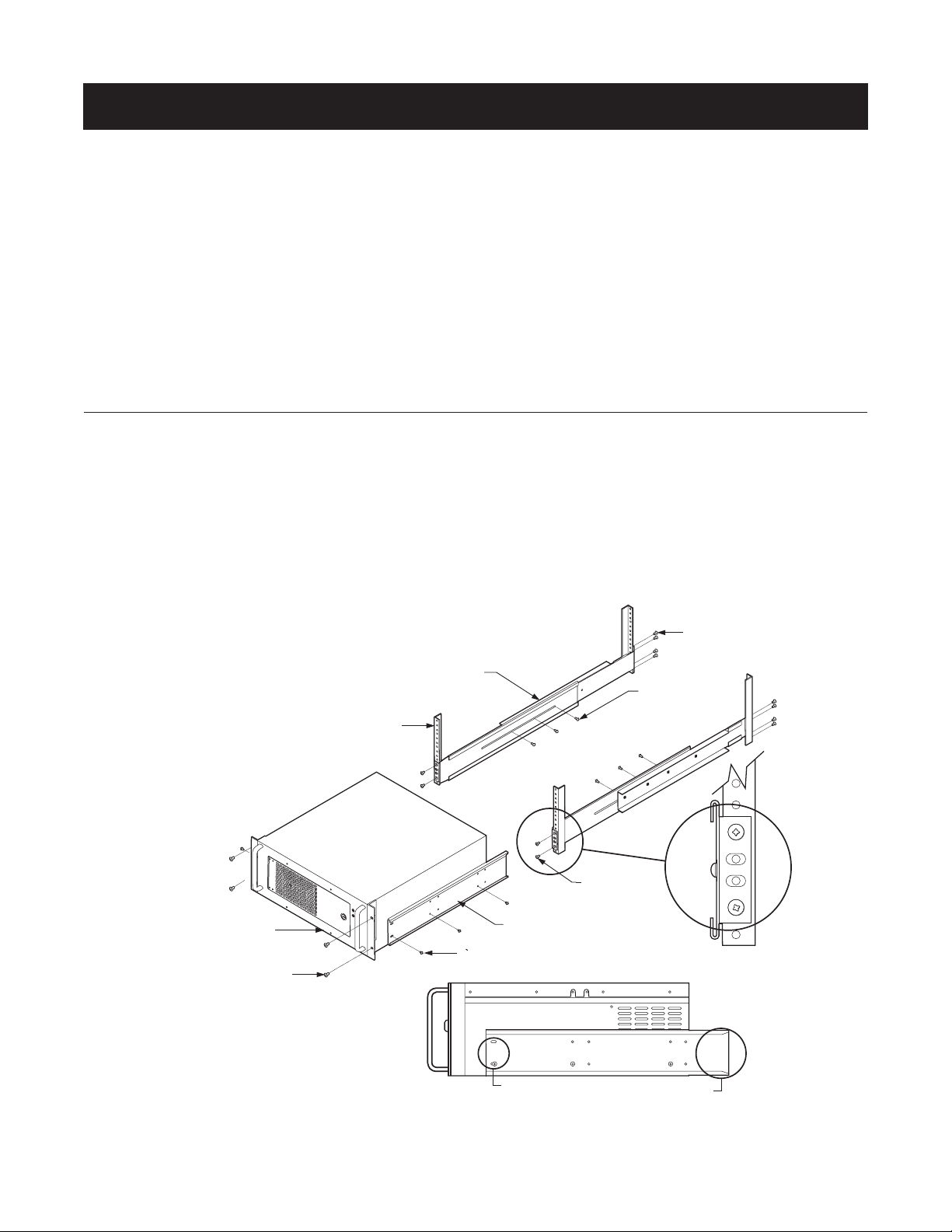
Installation of Support Rails
The following instructions replace the steps listed on page 11 of the Installation/Operation manual for installing the VMX200 in a 19-inch equipment rack.
Refer to Figure 1 for the following instructions.
1. Attach the rack ears to the front sides of the VMX200 with the 10-32 x 0.250-inch screws.
2. Attach the brackets to the sides of the equipment with the 8-32 x 0.250-inch screws.
3. Fasten the front and rear support rails together with the 8-32 x 0.375-inch screws with lock washers.
4. Attach the support rails to the equipment rack with the 10-32 x 0.375 inch screws.
5. Slide the brackets on the equipment onto the support rails.
6. Fasten the rack ears to the equipment rack with
the 10-32 x 0.750-inch screws and washers.
RACK
VMX200
(4) SCREWS,
10-32 X 0.750-INCH
PHILLIPS, PAN HEAD
WITH WASHERS
SUPPORT RAILS
(6) SCREWS, 8-32 X 0.250-INCH
PAN HEAD (3 EACH SIDE)
BRACKET
(SIDE VIEW)
(4) SCREWS,
10-32 X 0.375-INCH
FLAT HEAD
(8) SCREWS,
10-32 X 0.375-INCH,
FLAT HEAD
(6) SCREWS,
8-32 X 0.375-INCH,
PAN HEAD WITH
WASHERS
SLOTTED HOLES
TOWARDS FRONT
OF UNIT
Figure 1. Installation of Support Rails
TAPERED ENDS
TOWARDS REAR
OF UNIT
(Continued on next page
Page 2
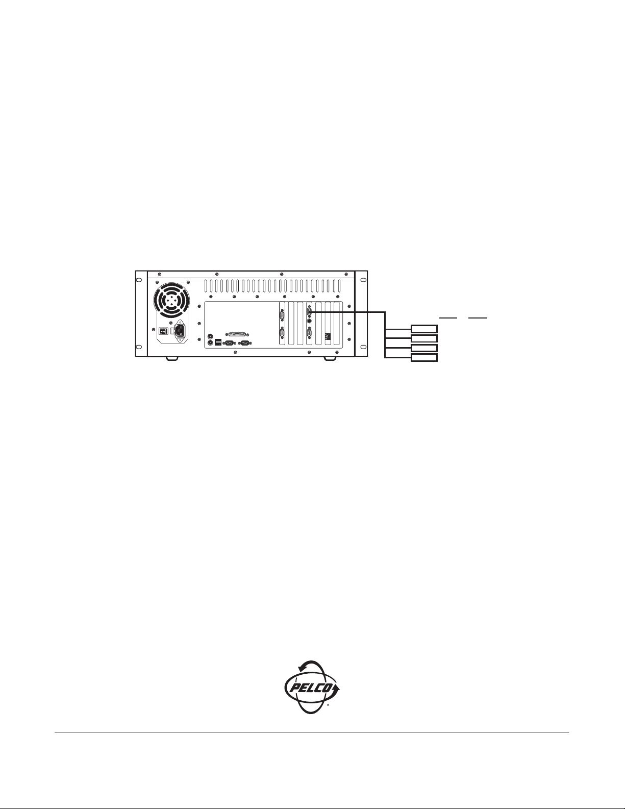
Connecting Analog Video to the VMX200-SYS-Q
The video input card that is supplied with the VMX200-SYS-Q has changed, and now it has only four video input connectors. The original configuration
described in the VMX200 Installation/Operation manual included the yellow input connector. Now the configuration uses the black input connector instead
of the yellow.
To connect video inputs to the VMX200-SYS-Q, complete the following steps and refer to Figure 2:
1. Connect the “spider” video input cable to the video port on the VMX200-SYS-Q rear panel.
2. Connect the four BNC connectors on the spider cable to the video source (for example, cameras or the monitor output of a switcher or multiplexer).
The spider cable contains four input connectors, coded by color. Use the BNC connectors as follows:
• Input 1 (Red)
• Input 2 (Green)
• Input 3 (Blue)
• Input 4 (Black)
NOTE: Refer to the appropriate installation manual for each video input device for additional instructions.
VMX200-SYS-Q
SPIDER
CABLE
Figure 2. How to Connect Analog Video to the VMX200-SYS-Q
INPUT COLOR
1
RED
2
GREEN
3
BLUE
4
BLACK
Worldwide Headquarters • 3500 Pelco Way • Clovis, California 93612 USA • www.pelco.com
USA & Canada • Tel: 800/289-9100 • Fax: 800/289-9150
International • Tel: 1-559/292-1981 • Fax: 1-559/348-1120
Page 3
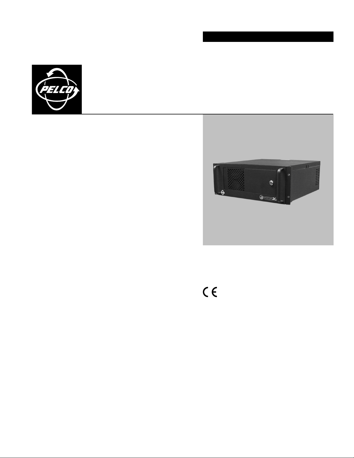
INSTALLATION/OPERATION
VMX200 Video
®
Management System
VMX200-SYS Series
C1525M-B (10/02)
Page 4

2 C1525M-B (10/02)
Page 5

CONTENTS
Section Page
IMPORTANT SAFEGUARDS AND WARNINGS .................................................................................................................................................................. 4
DESCRIPTION ..................................................................................................................................................................................................................... 5
MODELS .................................................................................................................................................................................................................... 5
OVERVIEW ................................................................................................................................................................................................................. 6
FRONT VIEW .....................................................................................................................................................................................................7
REAR VIEW ....................................................................................................................................................................................................... 8
INSTALLATION................................................................................................................................................................................................................... 10
MOUNTING .............................................................................................................................................................................................................. 11
CONNECTIONS ......................................................................................................................................................................................................... 12
MOUSE AND KEYBOARD ................................................................................................................................................................................ 12
MONITOR OUTPUTS ........................................................................................................................................................................................ 13
VIDEO INPUTS ................................................................................................................................................................................................. 14
DATA CONTROL ...............................................................................................................................................................................................16
SPECTRA/ESPRIT CONTROL CONNECTIONS.................................................................................................................................................. 16
CM6800 CONTROL CONNECTIONS ................................................................................................................................................................ 17
CM6700 CONTROL CONNECTIONS ................................................................................................................................................................ 18
CM9760/9740 CONTROL CONNECTIONS....................................................................................................................................................... 19
SERCOM PORTS ..................................................................................................................................................................................... 19
DATA TRANSLATOR................................................................................................................................................................................ 20
CM8500 CONTROL CONNECTIONS ................................................................................................................................................................ 21
GENEX MULTIPLEXER CONTROL CONNECTIONS ...........................................................................................................................................22
TLR3000 SERIES VCR CONTROL CONNECTIONS ........................................................................................................................................... 23
CM9760-ALM CONTROL CONNECTIONS ....................................................................................................................................................... 24
CM9760-REL CONTROL CONNECTIONS .........................................................................................................................................................25
OPERATION........................................................................................................................................................................................................................ 26
SPECIFICATIONS................................................................................................................................................................................................................ 26
REGULATORY NOTICES ..................................................................................................................................................................................................... 27
WARRANTY AND RETURN INFORMATION ...................................................................................................................................................................... 27
LIST OF ILLUSTRATIONS
Figure Page
1 System Overview .............................................................................................................................................................................................. 6
2 VMX200 Front View.......................................................................................................................................................................................... 7
3 VMX200 Rear View .......................................................................................................................................................................................... 8
4 Rack Mount Installation .................................................................................................................................................................................. 11
5 Mouse and Keyboard Connections ................................................................................................................................................................. 12
6 Monitor Connections ....................................................................................................................................................................................... 13
7Video Inputs .....................................................................................................................................................................................................15
8 Spectra/Esprit Control Connections ................................................................................................................................................................ 16
9 CM6800 Control Connections ......................................................................................................................................................................... 17
10 CM6700 Control Connections ......................................................................................................................................................................... 18
11 CM9760/CM9740 Control Connections to SERCOM Ports ............................................................................................................................. 19
12 CM9760/CM9740 Control Connections Using Data Translator ...................................................................................................................... 20
13 CM8500 Control Connections ......................................................................................................................................................................... 21
14 Genex Multiplexer Control Connections ......................................................................................................................................................... 22
15 TLR3000 Series VCR Control Connections ...................................................................................................................................................... 23
16 CM9760-ALM Control Connections ................................................................................................................................................................ 24
17 CM9760-REL Control Connections .................................................................................................................................................................. 25
C1525M-B (10/02) 3
Page 6
IMPORTANT SAFEGUARDS AND WARNINGS
Prior to installation and use of this product, the following WARNINGS should be observed:
1. Installation and servicing should be done only by qualified service personnel and conform to all local codes.
2. Unless the unit is specifically marked as a NEMA Type 3, 3R, 3S, 4, 4X, 6, or 6P enclosure, it is designed for indoor use
only and it must not be installed where exposed to rain and moisture.
3. The installation method and materials should be capable of supporting four times the weight of the unit and equipment.
The product and/or manual may bear the following marks:
This symbol indicates that dangerous voltage constituting a risk of
electric shock is present within this unit.
RISK OF ELECTRIC SHOCK.
This symbol indicates that there are important operating and maintenance instructions in the literature accompanying this unit.
Please familiarize yourself with the information in this manual prior to installation and operation.
CAUTION:
DO NOT OPEN.
4 C1525M-B (10/02)
Page 7

DESCRIPTION
The Pelco VMX200 Video Management System uses a Windows®-based interface for video security system control. You can
control matrix switchers, multiplexers, DVRs, VCRs, and Spectra
configurations and a visual interface. With a mouse, you can click a camera icon within your site map and drag it to a video
display window.
The VMX200 uses an interactive system schematic to simplify system configuration. This unique technique automatically
configures ports and devices while providing a schematic representation of the overall system.
With the VMX200 Video Management System, you have the option of using one of three dedicated workstations. Each
workstation includes a keyboard and mouse, a video capture card, and pre-installed VMX200 software.
The VMX200-SYS model uses a single monitor. A background map showing camera positions is overlaid with a display window
showing the camera video.
The VMX200-SYS-1 model uses two monitors. The left monitor shows a graphical map and the right monitor shows the camera
video.
VMX200-SYS-Q model also uses two monitors with the VMX map on the left monitor and the video from cameras displayed on
the right monitor.
You have full vision and control of a surveillance area with the two monitors mounted next to each other.
The following features are found on the VMX200:
•Visual interface for control of switchers, multiplexers, and other devices
• Simple and intuitive system control
• Drag and drop camera selection from maps to display monitors
• No more camera and monitor keyboard codes to remember
• On-screen, mouse-controlled PTZ functions
• Importation of maps directly from graphic programs
• Hierarchical linking of sets of maps (for example, buildings, floors, rooms)
• Automatic configuration of data ports and video buses
• Simplification of equipment integration, system growth, and modifications
• Easy definition, saving, and use of presets, sequences, and macros
• Automatic activation of presets, sequences, and macros in response to alarms
• Manual or automatic image capture
®
/Esprit™ camera positioning systems by using mapping
MODELS
VMX200-SYS Workstation to support video and graphical map on one monitor (monitor not supplied)
VMX200-SYS-1 Workstation to support a graphical map on one monitor and video on a second monitor (monitors not
supplied)
VMX200-SYS-Q Workstation to support a graphical map on one monitor and four interactive video displays on a second
monitor (monitors not supplied)
C1525M-B (10/02) 5
Page 8
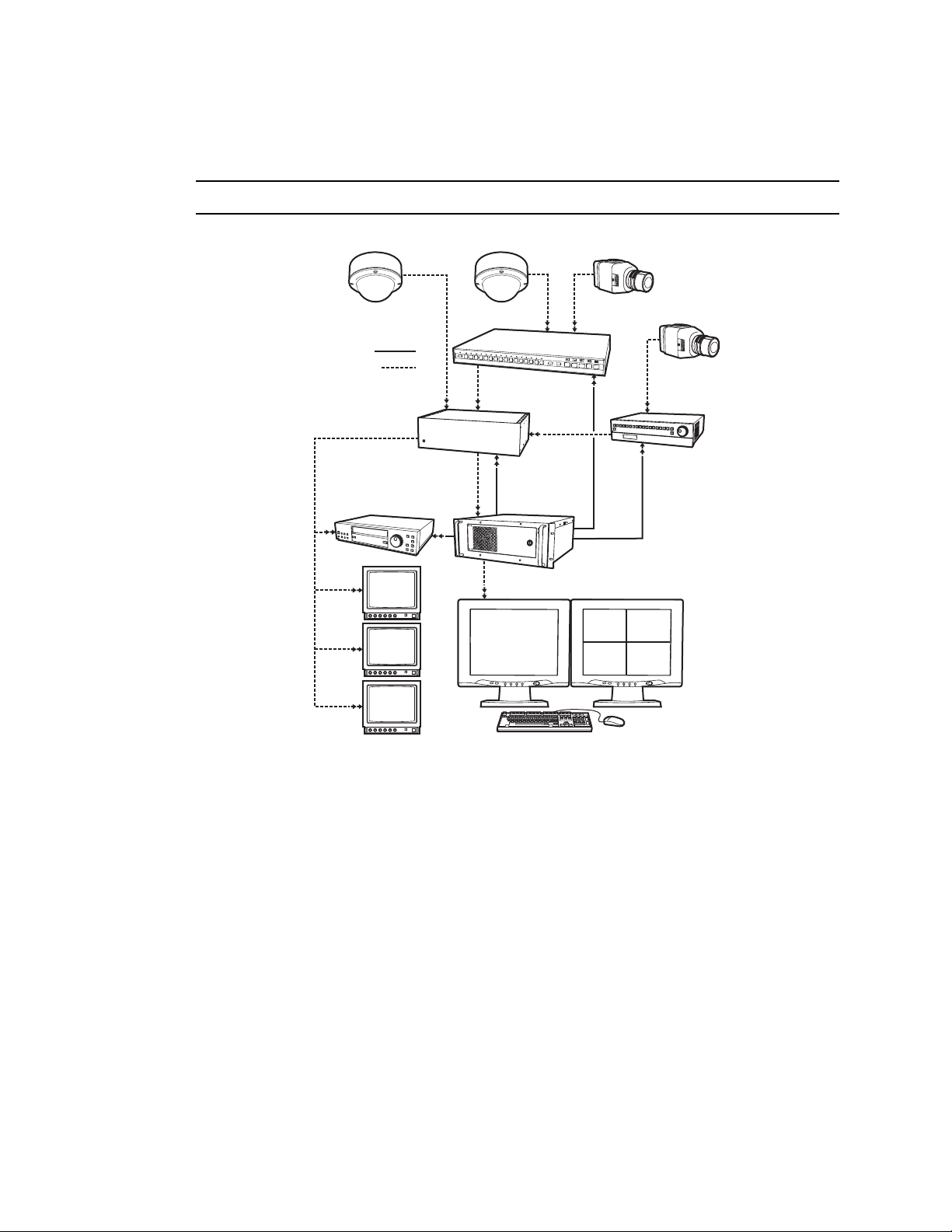
OVERVIEW
Figure 1 shows how equipment can be linked together on the VMX200 Video Management System. This illustration is only an
example. There are many ways you can link equipment together in this system.
NOTE: Each VMX200 workstation has two standard COM ports. Expansion is possible via the USB port.
DATA
VIDEO
MULTIPLEXER
VCR
MATRIX
SWITCHER
VMX200-SYS-Q
Figure 1. System Overview
DVR
6 C1525M-B (10/02)
Page 9
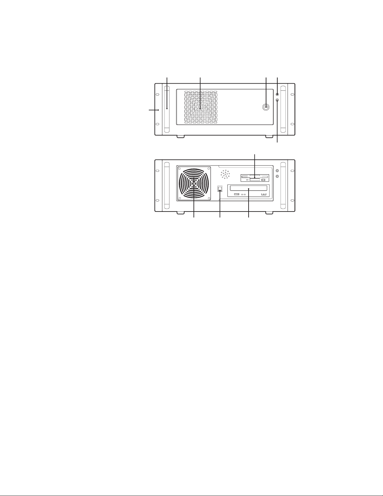
FRONT VIEW
Refer to Figure 2 to get familiarized with the front of the VMX200 workstation. The front of the unit has a door
that can be opened or locked using one of the supplied keys.
Figure 2. VMX200 Front View
POWER LED
HDD (HARD DISK DRIVE) LED
KEY LOCK (2 KEYS SUPPLIED)
FAN VENTILATION
HANDLES
RACK EARS
FAN
POWER BUTTON
CD-RW DRIVE
3.5-INCH FLOPPY DRIVE
C1525M-B (10/02) 7
Page 10

REAR VIEW
Figure 3 shows the rear of each VMX200 model. This system does not require the use of all of the ports.
VMX200-SYS
VMX200-SYS-1
VMX200-SYS-Q
Figure 3. VMX200 Rear View
8 C1525M-B (10/02)
Page 11

VMX200-SYS
MOUSE PORT
KEYBOARD PORT
USB PORT (NOT USED)
COM 1
COM 2
VIDEO INPUT*
VMX200-SYS-1
MOUSE PORT
KEYBOARD PORT
USB PORT (NOT USED)
COM 1
COM 2
VIDEO INPUT*
MONITOR PORT
ETHERNET PORT (NOT USED)
S-VHS VIDEO PORT (NOT USED)
F CONNECTOR PORT (NOT USED)
PARALLEL PORT***
LEFT MONITOR PORT
ETHERNET PORT (NOT USED)
DB15 PORT (NOT USED)
S-VHS VIDEO PORT (NOT USED)
F CONNECTOR PORT (NOT USED)
PARALLEL PORT***
RIGHT MONITOR PORT
VMX200-SYS-Q
MOUSE PORT
KEYBOARD PORT
USB PORT (NOT USED)
COM 1
COM 2
RIGHT MONITOR PORT**
ETHERNET PORT (NOT USED)
VIDEO INPUT*
LEFT MONITOR PORT
PARALLEL PORT***
* Refer to the video input details in Figure 7.
** Refer to the monitor connection details in Figure 6.
*** Refer to the Windows 2000 documentation for printer installation instructions.
C1525M-B (10/02) 9
Page 12

INSTALLATION
The following items are supplied:
•1VMX200 workstation
•1Mouse
•1Keyboard
•1Video input adapter
•1Y adapter (VMX200-SYS-Q) or 1 plug adapter (VMX200-SYS-1)
•2Power cords (1 USA standard and 1 European standard)
•2Adjustable support rails with screws and nuts
•2Rack-mount ears with screws
•2Keys
•1Video input card software package
•1VMX200 system software package
•1Windows 2000 startup package
One VGA or SVGA monitor is required for the VMX200-SYS and two VGA or SVGA monitors are required for the VMX200-SYS-1
and VMX200-SYS-Q.
10 C1525M-B (10/02)
Page 13

MOUNTING
E
The VMX200 can be placed on a flat surface, such as a shelf or table, or it can be mounted in a 19-inch (48.26 cm) equipment
rack.
Follow these instructions to mount the workstation in an equipment rack:
1. Attach the two adjustable support rails to the sides of the equipment rack using the eight 10-32 x .375-inch screws. Also
2. Tighten the eight 10-32 x .250 screws.
3. Attach the two rack ears to the front side of the VMX200 using the four 10-32 x .250 screws.
4. Place the workstation on the support rails. Use the handles on the VMX200 for easier placement. Remove the rubber feet
5. Fasten the rack ears to the rack using the four 10-32 x .750 screws.
use the eight 10-32 nuts if the rack does not have threaded mounting holes.
from the VMX200 if placing it on top of another device that is already in the rack.
10-32 X .375 SCREWS
LEAVE SCREWS LOOSE UNTIL
SUPPORT RAILS ARE ATTACHED TO THE
RACK , AND THEN TIGHTEN.
10-32 X .750
SCREWS
10-32 X .250 SCREWS
SLIDE FRONT TO BACK TO ADJUST RAILS
TO THE CORRECT DEPTH OF RACK
RACK EARS
MAKE SURE ARROWS FACE
TOWARDS THE FRONT OF THE RACK
LEFT SIDE
10-32 X .250
SCREWS
RIGHT SID
Figure 4. Rack Mount Installation
C1525M-B (10/02) 11
Page 14

CONNECTIONS
MOUSE AND KEYBOARD
Connect the mouse and keyboard to the workstation. Figure 5 shows the VMX200-SYS model, but the connections are the
same for the other two models.
VMX200-SYS
Figure 5. Mouse and Keyboard Connections
12 C1525M-B (10/02)
Page 15

MONITOR OUTPUTS
If you have the VMX200-SYS model, you have to connect only one monitor. The VMX200-SYS-1 and VMX200-SYS-Q each
require two monitors. Refer to Figure 6.
The VMX200-SYS-Q uses an overlay. This allows a quad display.
The location of the monitors is important. The graphical map monitor must always be placed on the left and the video display
monitor must always be placed on the right.
VMX200-SYS
VGA MONITOR
VMX200-SYS-1
LEFT VGA
MONITOR
RIGHT VGA
MONITOR
LEFT VGA
MONITOR
Figure 6. Monitor Connections
VMX200-SYS-Q
DB15
RIGHT VGA
MONITOR
C1525M-B (10/02) 13
Page 16

VIDEO INPUTS
The VMX200-SYS and VMX200-SYS-1 have one video input. The VMX200-SYS-Q has six video inputs.
Follow these steps and refer to Figure 7 to connect the video:
1. Connect a spider cable to the video port on each model.
2. Connect the video input to the video source (for example, cameras or monitor output of a switch or multiplexer).
NOTE: Refer to the Installation/Operation Manual for each device you connect for further video connection information.
For the VMX200-SYS and VMX200-SYS-1, only the yellow composite (RCA) connector goes to another device. The other three
connectors are not used.
For the VMX200-SYS-Q, you can connect the six BNC connectors to other devices. For example, you can connect them to six
cameras. However, you can only drag-and-drop four of the cameras into the quad display monitor.
The six BNC connectors are as follows:
1. Input 1 (Red)
2. Input 2 (Green)
3. Input 3 (Blue)
4. Input 4 (Yellow)
5. Input 5 (Black)
6. Input 6 (White)
Although there are six video inputs, there are several applications that require only four. For example, you would normally
connect only four inputs to video outputs on a CM6800-48X8.
14 C1525M-B (10/02)
Page 17

VMX200-SYS
SPIDER
CABLE
*
REQUIRES RCA-TO-BNC ADAPTER
SPIDER
CABLE
REQUIRES RCA-TO-BNC ADAPTER
*
S-VIDEO IN (BLACK)
AUDIO IN RIGHT (RED)
AUDIO IN LEFT (WHITE)
VIDEO IN (YELLOW)
*
VMX200-SYS-1
S-VIDEO IN (BLACK)
AUDIO IN RIGHT (RED)
AUDIO IN LEFT (WHITE)
VIDEO IN (YELLOW)
*
VMX200-SYS-Q
INPUT
COLOR
1
SPIDER
CABLE
2
3
4
5
RED
GREEN
BLUE
YELLOW
BLACK
Figure 7. Video Inputs
C1525M-B (10/02) 15
Page 18

DATA CONTROL
VMX200 -SYS
The following sections provide instructions and illustrations on how to connect numerous devices to the VMX200 for data control.
Each application shows a VMX200-SYS for illustration purposes only. You can also use a VMX200-SYS-1 or VMX200-SYS-Q.
NOTE: You can use either COM 1 or COM 2 on the VMX200 for control.
SPECTRA/ESPRIT CONTROL CONNECTIONS
To connect a Spectra or Esprit to a VMX200 for direct camera control, you must use a PV130 converter to convert the RS-232
interface to an RS-422 interface.
Follow these steps and refer to Figure 8:
1. Connect the RS-232 side of the PV130 converter to either COM 1 or COM 2 on the VMX200.
2. Use twisted pair wire to connect from TX+ and TX- on the PV130 converter to RX+ and RX- on the Spectra or Esprit. You
can daisy-chain from the RX+ and RX- connections on the first Spectra or Esprit to additional units.
VMX200 COM
PORT SETTINGS
BAUD RATE:
DATA BITS:
PARITY:
STOP BITS:
FLOW CONTROL:
9600
NONE
NONE
8
1
*12 VDC POWER SUPPLY
*IF NECESSARY
GND
+12V
RX+
RX-
TO RECEIVER(S)
ESPRIT
SPECTRA
Figure 8. Spectra/Esprit Control Connections
After you make the connections, open the Device Configuration window in the VMX200 software and add the receiver to your
system. Make sure you specify the following:
• Specify that the commands are sent via PC serial control port.
• Specify the D-Protocol driver.
• Select either “automatic” or “manual” camera addressing.
Refer to the VMX200 Software Installation/Operation Manual for detailed instructions on system configuration.
The receiver’s settings must match the VMX200 COM port settings. Refer to the Spectra/Esprit Installation/Operation Manuals
for instructions on setting baud rate, parity, and other settings.
16 C1525M-B (10/02)
Page 19

CM6800 CONTROL CONNECTIONS
There are two ways you can connect a CM6800 to a VMX200.
Connect a null modem cable from VMX200 COM 1 or COM 2 to the CM6800 COM 1 port.
Connect a DB9 cable from VMX200 COM 1 or COM 2 to the CM6800 ASCII Ports 2, 7, or 8. You must use a wall block to
convert the DB9 connector to an RJ-45 connector.
Figure 9. CM6800 Control Connections
Although a CM6800-48X8 is pictured above, you can use a CM6800-32X6 as long as the COM port number of the port
connection is the same. (COM ports 7 and 8 are not available on the CM6800-32X6.)
If you connect to ports 7 or 8, you must set the port for ASCII RS-232 using the CM6800 programming menus or manager
program.
After you make the connections, open the Device Configuration window in the VMX200 software and add the CM6800 to your
system. Refer to the VMX200 Software Installation/Operation Manual for detailed instructions on system configuration.
The CM6800 settings must match the VMX200 COM port settings. Refer to the CM6800 Installation/Operation Manual for
instructions on setting baud rate, parity, and other settings.
C1525M-B (10/02) 17
Page 20

CM6700 CONTROL CONNECTIONS
T
T
Follow these steps and refer to Figure 10:
1. Connect a DB9 cable from VMX200 COM 1 or COM 2 to the screw terminal connector on the CM6700. Note the pin-outs
on the wiring.
2. Remove the cover from the CM6700-MXB and set the SW5 DIP switch to RS-232 mode. Replace the cover when done.
After you make the connections, open the Device Configuration window in the VMX200 software and add the CM6700 to your
system. Refer to the VMX200 Software Installation/Operation Manual for detailed instructions on system configuration.
The CM6700 settings must match the VMX200 COM port settings. Refer to the CM6700 Installation/Operation Manual for
instructions on setting baud rate, parity, and other settings.
VMX200 -SYS
VMX200 COM
PORT SETTINGS
BAUD RATE:
DATA BITS:
STOP BITS:
PARITY:
FLOW CONTROL:
9600
1
NONE
NONE
8
RS-232
1 2 3 4 5 6 7 8 9
ALARMS
(1-9)
ALARMS
(10-18)
10
1 2 3 4 5 6 7 8 9 10
1 2 3 4 5 6 7 8 9
10
11
1213 1415 16 1718
1 2 3 4 5 6 7 8 9 10
F3NONCC
F
0123
2
COM 1 OR 2
2
3
5
VIDEO INPUTS
13579
2468101112 14
NOTE: TO PROPERLY SHIELD DATA CABLE
CONNECT GROUND ON ONE END ONLY
SW5 DIP SWITCH SETTINGS
RS-422/485
ON
1 2 3 4 5 6 7 8
RS-232
ON
1 2 3 4 5 6 7 8
KEY
ON OFF
RXD
TXD
GND
13 15
16
CM6700-MXB
COM 2
TXD
7
RXD
12
GND
9
VIDEO OUTPUTS
1
2
COM 1 (1-6)
COM 2 (7-12)
CONTROL
OUTPUTS
SET DIP SWITCH (SW5) ON CM6700-MXB TO RS-232 MODE
11
1213 14 15 16 1718
0123
LOCAL
KEYBOARD
REMOTE KEYBOARD(S)
TT RR
11
12
+ +
O
M
CM6700-MXB
F
2
11
F3NONCC
REMO
T
12
+
O
M
Figure 10. CM6700 Control Connections
18 C1525M-B (10/02)
Page 21

CM9760/9740 CONTROL CONNECTIONS
There are two ways you can make the connections:
1. Via SERCOM Ports
2. Via Data Translator
SERCOM Ports
This is called the Virtual Keyboard Method because the SERCOM ports used for the VMX200 must be programmed as keyboard
ports. Pelco recommends this method because it supports all system control functions.
Follow these steps and refer to Figure 11.
1. Connect a PV130 converter to VMX200 COM 1 or COM 2.
2. Wire an RJ-45 reversed cable from the PV130 to the CM9760-CC1 or CM9740-CC1 RS-422 SERCOM port. For
convenience, use a wall block to connect the RJ-45 reversed cable to the SERCOM port.
3. Program the CC1's SERCOM port as a keyboard port.
Figure 11 shows two VMX200 workstations. For a single VMX200 workstation, use only one SERCOM port.
After you make the connections, open the Device Configuration window in the VMX200 software and add the CM9760/9740 to
your system. Refer to the VMX200 Software Installation/Operation Manual for detailed instructions on system configuration.
The CM9760/9740 settings must match the VMX200 COM port settings. Refer to the CM9760/9740 Installation/Operation
Manuals for instructions on setting baud rate, parity, and other settings.
Figure 11. CM9760/CM9740 Control Connections to SERCOM Ports
C1525M-B (10/02) 19
Page 22

Data Translator
M
You can also connect the CPU to a VMX200 via the CM9760-DT. This method does not allow complete control of cameras
connected serially to the CM9760/9740-CC1 (including presets). Therefore, Pelco recommends this method only for situations
where the Virtual Keyboard Method is not possible.
Follow these steps and refer to Figure 12:
1. Connect a null modem cable from VMX200 COM 1 or COM 2 to CM9760-DT COM A.
2. Connect another null modem cable from CM9760-DT COM B to an RS-232 COM port on either the CM9760-CC1 or
CM9740-CC1.
3. Program the CC1’s RS-232 port for ASCII protocol.
After you make the connections, open the Device Configuration window in the VMX200 software and add the CM9760/9740 to
your system. Refer to the VMX200 Software Installation/Operation Manual for detailed instructions on system configuration.
The CM9760/9740 settings must match the VMX200 COM port settings. Refer to the CM9760/9740 Installation/Operation
Manuals for instructions on setting baud rate, parity, and other settings.
VMX200 -SYS
NULL MODEM
CABLE
VMX200 COM
PORT SETTINGS
DATA BITS:
STOP BITS:
FLOW CONTROL:
8
1
NONE
A
B
PRINTER COM1 COM2
CM9760-DT
1 2
CM9760-CC1
OR
CM9740-CC1
12 VAC
CM9760-CC1
RS-232
CM9740-CC1
Figure 12. CM9760/CM9740 Control Connections Using Data Translator
NULL
MODE
CABLE
20 C1525M-B (10/02)
Page 23

CM8500 CONTROL CONNECTIONS
1. Connect a null modem cable from VMX200 COM 1 or COM 2 to the DB9 connector on the CM8500-DT.
2. Connect an RJ-45 straight cable from the RJ-45 connector on the CM8500-DT to one of the RJ-45 connectors on the
CM8500.
After you make the connections, open the Device Configuration window in the VMX200 software and add the CM8500 to your
system. Refer to the VMX200 Software Installation/Operation Manual for detailed instructions on system configuration.
The CM8500 settings must match the VMX200 COM port settings. Refer to the CM8500 Installation/Operation Manual for
instructions on setting baud rate, parity, and other settings.
Figure 13. CM8500 Control Connections
C1525M-B (10/02) 21
Page 24

GENEX MULTIPLEXER CONTROL CONNECTIONS
Follow these steps and refer to Figure 14:
1. Connect a DB9 cable from VMX200 COM 1 or COM 2 to a wall block. Note the pin-outs. Pins 1 and 8 are tied together
with Pin 5.
2. Connect an RJ-45 straight cable from the wall block to the Genex® COM OUT port.
After you make the connections, open the Device Configuration window in the VMX200 software and add the Genex Multiplexer to your system. Refer to the VMX200 Software Installation/Operation Manual for detailed instructions on system
configuration.
The Genex Multiplexer settings must match the VMX200 COM port settings. Refer to the Genex Multiplexer Installation/
Operation Manual for instructions on setting baud rate, parity, and other settings.
Figure 14. Genex Multiplexer Control Connections
22 C1525M-B (10/02)
Page 25

TLR3000 SERIES VCR CONTROL CONNECTIONS
Connect a null modem cable from VMX200 COM 1 or COM 2 to the TLR3168/TLR3096 RS-232 serial port. Refer to Figure 16.
NOTE: Pelco recommends that the null modem cable be checked with an ohmmeter to ensure that the pin connections match
those listed in the figure below.
After you make the connections, open the Device Configuration window in the VMX200 software and add the VCR to your system.
Refer to the VMX200 Software Installation/Operation Manual for detailed instructions on system configuration.
The TLR3000 settings must match the VMX200 COM port settings. Refer to the TLR3000 Installation/Operation Manual for
instructions on setting baud rate, parity, and other settings.
Figure 15. TLR3000 Series VCR Control Connections
C1525M-B (10/02) 23
Page 26

CM9760-ALM CONTROL CONNECTIONS
Follow these steps and refer to Figure 16:
1. Connect a PV130 converter to VMX200 COM 1 or COM 2.
2. Wire a cable from the PV130 to a wall block.
3. Connect an RJ-45 reversed cable from the wall block to the COM IN connector on the CM9760-ALM.
After you make the connections, open the Device Configuration window in the VMX200 software and add the CM9760-ALM to
your system. Refer to the VMX200 Software Installation/Operation Manual for detailed instructions on system configuration.
The CM9760-ALM settings must match the VMX200 COM port settings. Refer to the CM9760-ALM Installation/Operation
Manual for instructions on setting baud rate, parity, and other settings.
VMX200-SYS
TD(A)
TD(B)
RD(A)
RD(B)
GND
+12 VDC
PV130
DETAIL
5
3 4 6
2
7
8
1
WALL BLOCK
DETAIL
VMX200 COM PORT SETTINGS
RS-232 DATA
PV130
+12 VDC
GND
RD(B)
RD(A)
TD(B)
TD(A)
RS-422
DATA
REVERSED
CABLE
RJ-45
3 4 6
2
1
RS-422
5
7
8
VMX200 DB9
CONNECTOR
PIN 2
PIN 3
PIN 5
CM9760-ALM
Figure 16. CM9760-ALM Control Connections
BAUD RATE:
DATA BITS:
STOP BITS:
PARITY:
FLOW CONTROL:
RX
TX
GND
CM9760-ALM
COM IN RJ-45
CONNECTOR
PIN 1
PIN 2
PIN 7
PIN 8
4800
NONE
NONE
TX+
TXRXRX+
8
1
24 C1525M-B (10/02)
Page 27

CM9760-REL CONTROL CONNECTIONS
Follow these steps and refer to Figure 17:
1. Connect a PV130 converter to VMX200 COM 1 or COM 2.
2. Wire a cable from the PV130 to a wall block.
3. Connect an RJ-45 reversed cable from the wall block to the COM IN connector on the CM9760-REL.
After you make the connections, open the Device Configuration window in the VMX200 software and add the CM9760-REL to
your system. Refer to the VMX200 Software Installation/Operation Manual for detailed instructions on system configuration.
The CM9760-REL settings must match the VMX200 COM port settings. Refer to the CM9760-REL Installation/Operation
Manual for instructions on setting baud rate, parity, and other settings.
VMX200-SYS
TD(A)
TD(B)
RD(A)
RD(B)
GND
+12 VDC
PV130
DETAIL
5
4
3
6
2
7
1 8
WALL BLOCK
DETAIL
VMX200 COM PORT SETTINGS
RS-422 DATA
PV130
+12 VDC
GND
RD(B)
RD(A)
TD(B)
TD(A)
RS-232
CABLE
RJ-45
REVERSED
CABLE
3 4 6
2
1
RS-422
5
7
8
VMX200 DB9
CONNECTOR
PIN 2
PIN 3
PIN 5
CM9760-REL
Figure 17. CM9760-REL Control Connections
BAUD RATE:
DATA BITS:
STOP BITS:
PARITY:
FLOW CONTROL:
RX
TX
GND
COM IN RJ-45
CONNECTOR
9600
EVEN
NONE
CM9760-REL
PIN 1
TX+
PIN 2
TX-
PIN 7
RX-
PIN 8
RX+
8
1
C1525M-B (10/02) 25
Page 28

OPERATION
Refer to the VMX200 Software Installation/Operation Manual for instructions on how to operate the Video Management
System.
SPECIFICATIONS
ELECTRICAL
Input Voltage: 100-240 VAC, 50/60 Hz, auto-ranging
Signal System (NTSC/PAL)
VMX200-SYS: VMX200 software-selectable
VMX200-SYS-1: VMX200 software-selectable
VMX200-SYS-Q: Auto-sensing
Video Outputs
Single Monitor Systems: 1 SVGA
Dual Monitor Systems: 2 SVGA
Power Consumption: 180W maximum
MECHANICAL
Connectors
Video Inputs: BNC
PS/2 Mouse and Keyboard: 6-pin mini-DIN
SVGA Monitor Port: 15-pin D-type
Printer Port: 25-pin D-type
10/100 TCP/IP Port: RJ-45
COM 1 and 2: 9-pin D-type
GENERAL
Operating Temperature: 41° to 104°F (5° to 40°C)
Relative Humidity: Maximum 80% non-condensing
Dimensions
Desktop: 7.3 (H) x 17.0 (W) x 19.6 (D) inches (18.5 x 43.2 x 49.8 cm)
Rack Mount: 7.0 (H) x 19.0 (W) x 19.6 (D) inches (17.8 x 48.3 x 49.8 cm)
Unit Weight: 27 lb (12.27 kg)
Shipping Weight: 55 lb (24.9 kg) maximum
(Design and product specifications subject to change without notice.)
26 C1525M-B (10/02)
Page 29

REGULATORY NOTICES
This equipment has been tested and found to comply with the limits of a Class B digital device, pursuant to part 15 of the FCC
rules. These limits are designed to provide reasonable protection against harmful interference in a residential installation. This
equipment generates, uses, and can radiate radio frequency energy and, if not installed and used in accordance with the
instructions, may cause harmful interference to radio communications. However there is no guarantee that the interference
will not occur in a particular installation. If this equipment does cause harmful interference to radio or television reception,
which can be determined by turning the equipment off and on, the user is encouraged to try and correct the interference by one
or more of the following measures:
• Reorient or relocate the receiving antenna.
• Increase the separation between the equipment and the receiver.
• Connect the equipment into an outlet on a circuit different from that to which the receiver is connected.
• Consult the dealer or an experienced radio/TV technician for help.
WARRANTY AND RETURN INFORMATION
WARRANTY
Pelco will repair or replace, without charge, any merchandise proved defective in material or
workmanship for a period of one year after the date of shipment. Exceptions to this warranty are
as noted below:
• Five years on Pelco manufactured cameras (CC3500/CC3600/CC3700 and MC3500/MC3600
Series); two years on all other cameras.
• Three years on Genex® Series (multiplexers, server, and keyboard).
•Two years on all standard motorized or fixed focal length lenses.
•Two years on Legacy®, Camclosure™ Camera Systems, CM6700/CM6800/CM8500/CM9500/
CM9740/CM9760 Matrix, DF5 and DF8 Series Fixed Dome products.
•Two years on Spectra®, Esprit™, and PS20 Scanners, including when used in continuous
motion applications.
•Two years on Esprit and WW5700 series window wiper (excluding wiper blades).
• Eighteen months on DX Series digital video recorders.
• One year (except video heads) on video cassette recorders (VCRs). Video heads will be
covered for a period of six months.
• Six months on all pan and tilts, scanners or preset lenses used in continuous motion applications (that is, preset scan, tour and auto scan modes).
Pelco will warrant all replacement parts and repairs for 90 days from the date of Pelco
shipment. All goods requiring warranty repair shall be sent freight prepaid to Pelco, Clovis,
California. Repairs made necessary by reason of misuse, alteration, normal wear, or accident
are not covered under this warranty.
Pelco assumes no risk and shall be subject to no liability for damages or loss resulting from the
specific use or application made of the Products. Pelco’s liability for any claim, whether based on
breach of contract, negligence, infringement of any rights of any party or product liability, relating
to the Products shall not exceed the price paid by the Dealer to Pelco for such Products. In no
event will Pelco be liable for any special, incidental or consequential damages (including loss of
use, loss of profit and claims of third parties) however caused, whether by the negligence of
Pelco or otherwise.
The above warranty provides the Dealer with specific legal rights. The Dealer may also have
additional rights, which are subject to variation from state to state.
If a warranty repair is required, the Dealer must contact Pelco at (800) 289-9100 or (559) 292-1981 to
obtain a Repair Authorization number (RA), and provide the following information:
1. Model and serial number
2. Date of shipment, P.O. number, Sales Order number, or Pelco invoice number
3. Details of the defect or problem
If there is a dispute regarding the warranty of a product which does not fall under the warranty conditions
stated above, please include a written explanation with the product when returned.
Method of return shipment shall be the same or equal to the method by which the item was received by
Pelco.
RETURNS
In order to expedite parts returned to the factory for repair or credit, please call the factory at (800) 2899100 or (559) 292-1981 to obtain an authorization number (CA number if returned for credit, and RA
number if returned for repair).
All merchandise returned for credit may be subject to a 20% restocking and refurbishing charge.
Goods returned for repair or credit should be clearly identified with the assigned CA or RA number and
freight should be prepaid. Ship to the appropriate address below.
If you are located within the continental U.S., Alaska, Hawaii or Puerto Rico:
Service Department
Pelco
3500 Pelco Way
Clovis, CA 93612-5699
If you are located outside the continental U.S., Alaska, Hawaii or Puerto Rico:
Intermediate Consignee Ultimate Consignee
American Overseas Air Freight Pelco
320 Beach Road 3500 Pelco Way
Burlingame, CA 94010 Clovis, CA 93612-5699
USA USA
REVISION HISTORY
Manual # Date Comments
C1525M 5/02 Original version.
C1525M-A 8/02 Changed Left VGA Monitor connection on the VMX200-SYS-1 model on Figure 6. Switched call-out 8 with call-out 10 on the VMX200-SYS-1 on page 9. Revised
C1525M-B 10/02 Added CM8500 section. Revised Figure 11.
® Pelco, the Pelco logo, Spectra, Genex, and Legacy Coaxitron are registered trademarks of Pelco. ® Windows is a registered trademark of Microsoft Corporation.
™ Esprit and Camclosure are trademarks of Pelco. © Copyright 2002, Pelco. All rights reserved.
C1525M-B (10/02) 27
COM Port Settings on Figure 10. Wall block pin outs changed on Figure 13. Removed DX3000 and PelcoNet sections. Added CM9760-ALM and CM9760-REL
sections.
Page 30

®
World Headquarters
3500 Pelco Way
Clovis, California 93612 USA
USA & Canada
Tel: 800/289-9100
Fax: 800/289-9150
International
Tel: 1-559/292-1981
Fax: 1-559/348-1120
www.pelco.com
ISO9001
Orangeburg, New York Las Vegas, Nevada Eindhoven, The Netherlands Wokingham, United Kingdom Montreal, Canada
 Loading...