

Page 1

ADDENDUM
Addendum No.: C1577M-A
Date: August 4, 2004
Manuals Affected: CM9760 Series Manuals – C538M, C539M-A, C540M-B, C541M-C, C542M-B, C543M-A,
C544M, C549M-A, C572M, C573M-D, C578M, C579M, C1501M, C1503M, C1510M-QS,
C1510M-A, C1520M-B, C1528M-C, C1940M, C1941M, C1942M, and C1943M
Manual Update: The CM9760-CC1 has been replaced with the CM9700-CC1 and the CM9760-MGR manage-
ment software has been replaced with the CM9700-MGR management software.
Keep the following in mind when referring to the instructions contained in these manuals:
• The CM9700-CC1 contains the latest CC1 software (version 9.01 or higher), and is
programmed with the new CM9700-MGR management software.
• Despite the difference in model numbers, the CM9700-CC1 functions the same as the
CM9760-CC1 and most of the information in these manuals applies to version 9.01 (or
higher) CPU.
•You can add the CM9700-CC1 to an existing CM9760 system if you upgrade the existing
CM9760-CC1 units with the current software (version level 9.01 or higher).
Software version 9.01 requires a minimum of 16 MB of RAM in the CPU. If required, you
can upgrade the RAM in older CM9760-CC1 units using the software upgrade kit
appropriate for your CPU.
• Do not use the CM9760-MGR instructions contained in these manuals. Refer to the
CM9700-MGR Getting Started Software Guide, on-screen help, or Online Help for
instructions.
Pelco World Headquarters • 3500 Pelco Way, Clovis, California 93612-5699 USA • www.pelco.com
USA & Canada: Tel: 800/289-9100 • Fax: 800/289-9150
®
International: Tel: 1-559/292-1981 • Fax: 1-559/348-1120
Page 2
CM9760-SAT QUICK START
REFERENCE GUIDE FOR:
the 9760-SAT physical interface
setup parameters for SAT programming from the 9760-KBD
®
CONNECT
THE CC1 TO THE SAT (RS-422)
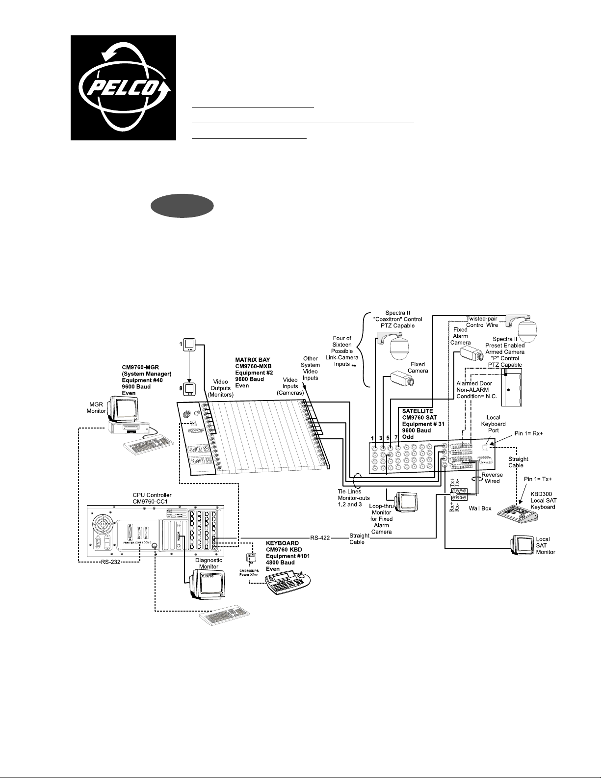
Figure 1 shows a CM9760-SAT connected to a 9760 system. Of particular interest are the COMM
and tie line connections. The COMM connection shown in Figure 1 is the line between port 7
on the CC1 and the COM 2 connection on the SAT. This is detailed in Figure 2.
FIGURE 1
alarm implementation issues
C1510M-QS – CM9760-SAT Quick Start Reference Guide
–1–
Page 3
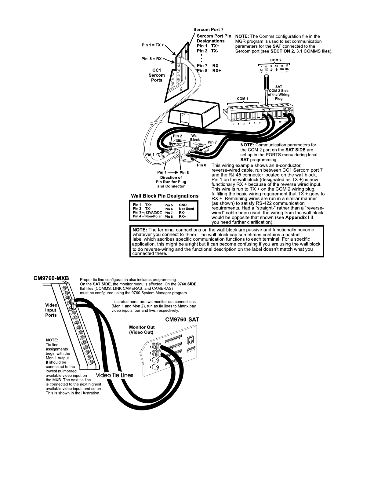
FIGURE 2
THE CC1 TO THE SAT (TIE LINES)
Tie lines (a minimum of one, a maximum of four) are
connected in sequential, ascending order to monitorouts on the SAT. Don’t skip around. Use Figure 3 as
a guide.
FIGURE 3
C1510M-QS – CM9760-SAT Quick Start Reference Guide
–2–
Page 4

SETUP
PARAMETERS FOR SAT PROGRAMMING
In order to program and operate the SAT from the 9760-KBD,
some preparatory groundwork must be laid by programming the
following 9760 configuration files: the Comms, Camera and Link
Camera files. Use Figures 4, 5 and 6, respectively, as guides.
These are essentially the only files that need to be programmed
on the 9760 SIDE for basic SAT operation.
FIGURE 5
FIGURE 4
FIGURE 6
SAT MENU ACCESS
FROM THE 9760-KBD
Programming SAT menus using a KBD200, 300 or 300V is the preferred method (it’s easier and faster); otherwise, the 9760-KBD can be
used. To access the SAT Main menu screen from the 9760-KBD requires that:
the programming files listed in SETUP be configured and loaded
the CC1 is initialized and the COMM link between the CC1 and SAT is active
at least one tie line is physically connected between the SAT and CC1
Next, ensure no one else (9760 SIDE) is using an SAT tie line.
Then:
1. Call up any link camera programmed in the Link Camera file of the MGR (see Figure 6). Use the associated logical number for the
camera.
NOTE: It is not necessary for the Link camera called to actually be connected to the SAT at this time. All that is happening here
is that you, as the operator, are “isolating” a video tie line for the display transfer of the SAT menu to a 9760 monitor.
2. Press the or the
3. Enter 89 in the keypad and press the PRST key (while still in the DEF menu). The main SAT programming menu will appear on the
monitor in front of you. You may now proceed to program the SAT.
key, then press the DEF key. If this is the first time accessing that menu, enter the default PIN (1234).
C1510M-QS – CM9760-SAT Quick Start Reference Guide
–3–
Page 5

ALARM IMPLEMENTATION ISSUES
(if needed, reference the attached Default SAT Menu Settings Sheet)
Alarm programming involves configuring SAT Monitor and Alarm
menus and, possibly, some 9760 System configuration files. If you
program alarm functions without regard to the status of the
monitor-out lines on the SAT, you are going to get into trouble.
There is only one source of alarms on the SAT: the physical
actuation of a relay input, going from its non-alarm to its alarm
state. On the other hand, there are three alarm-reporting destinations possible and each destination is dependent on associated
programming configurations. In one, the alarm is seen and acted
upon by the LOCAL SAT only. In another, the alarm is seen and
acted upon by the 9760 System only. Finally, the alarm can be seen
and acted upon by both the LOCAL SA T and the 9760 System at
the same time.
LOCAL ONLY
For LOCAL SAT alarm viewing and reporting, at least one
monitor-out line on the SAT must be configured as LOCAL and,
connected to it, there should be a physical monitor for viewing
purposes.
For the monitor connected to the monitor-out line just referenced, do the following:
For each destination to be programmed, Pelco recommends that
you not stray outside the guidelines outlined below for programming the various menus until you are quite familiar with the
ramifications of doing so. Improper programming can lead to
unexpected (but not uncorrectable) results that might lead you to
believe that your equipment isn’t operating properly. This built-in
alarm reporting flexibility allows for a more versatile, dynamic,
alarm environment. The trade-off is that you must be observant
when configuring the menus.
SYSTEM ONLY
For 9760 SIDE alarm viewing and reporting, at least one
monitor-out line on the SAT must be configured as a TIE LINE and
it should be connected to a video input line on the CM9760-MXB
for viewing purposes.
For the monitor-out line just referenced as a tie line, do the
following:
In the SAT menus
listed below Do the following
MONITOR
MENU
ALARM
MENU
➟
➟
➟
➟
➟
➟
➟
Set ALM TYPE to AUTO or MAN
Set VIEW to LOCAL
In the ALARM ENABLE sub-menu:
enable alarms to be viewed
For the alarm inputs desired, choose an
activation TYPE ( N.O. or N.C.)
ARM the alarm in the LOCAL column*
Assign a preset # (PRE) if the alarm
camera is preset capable and you want a
preset called
Make sure the System Alarm columns
are zeroed-out.
* Remember, ALM 1 calls SAT camera 1,
ALM 2 calls SAT camera 2, and so on.
In the SAT menus
listed below Do the following
MONITOR
MENU
ALARM
MENU
➟
➟
➟
➟
➟
➟
➟
Set ALM TYPE to OFF
Set VIEW to TIE LINE
In the ALARM ENABLE sub-menu,
disable all alarms
For the alarm inputs desired, choose an
activation TYPE (N.O. or N.C.)
DIS-ARM (- -) all alarms in the LOCAL
ARM column
Zero-out all presets
Enter a physical alarm # (as configured
in the 9760-CC1) in the SYSTEM
ALARMS column. *
* This is the alarm that will be triggered
on the CM9760-CC1.
➟
C1510M-QS – CM9760-SAT Quick Start Reference Guide
–4–
Page 6

SYSTEM ONLY (Continued)
➟
System-only implementation of alarms also requires that configuration files be programmed on the 9760 SIDE of the configuration. In the
Systems Configuration file, specify an Alarm Control Mode of operation.
FIGURE 7
More importantly, in the Comms Configuration file:
Assign alarm monitors for the 9760 operator
➟
to view alarms on.
Of equal importance is the CC1 Alarms file:
Fill in the alarm information fields opposite
➟
the physical alarm # that matches the System Alarm
# entered in the contact menu of the SAT Alarms
file (see the SYSTEM ALARMS column reference
under SYSTEM ONLY in the SAT Alarm Menu).
FIGURE 8
C1510M-QS – CM9760-SAT Quick Start Reference Guide
–5–
Page 7

COMBINED LOCAL AND SYSTEM
Here, you need to pay close attention to the specific monitor-out line you are setting menu attributes for. For all monitor-outs connected to a
LOCAL monitor, assign Monitor menu attributes just as they were listed and discussed under LOCAL ONLY.
For all monitor-outs configured as a TIE LINE, assign Monitor menu attributes just as they were listed and discussed under SYSTEM ONLY.
The difference between LOCAL ONLY and SYSTEM ONLY as opposed to COMBINED or shared alarm implementation appears when the menu
attributes in the Contact menu of the SAT ALARM file are assigned. It is here that we accommodate both LOCAL and SYSTEM alarm activation
at the same time. This can best be seen in a side-by-side comparison of the menus for the three states of alarm activation.
FIGURE 9
To complete alarm implementation for the combined
example, you must carry through the System Alarm
portion of the menu settings in the same manner that
was done for System Alarm Only. That is, configure the
9760 CC1 configuration menus (System, Comms, and
Alarm files), just as they were listed and discussed
under SYSTEM ONLY.
C1510M-QS – CM9760-SAT Quick Start Reference Guide
–6–
Page 8

SAT DEFAULT
MENU SETTINGS
C1510M-QS – CM9760-SAT Quick Start Reference Guide
–7–
Page 9

®
Pelco
3500 Pelco Way
Clovis, CA 93612-5699 USA
In North America and Canada
Tel (800) 289-9100 • FAX (800) 289-9150
International Customers
Tel +1(559) 292-1981 • FAX +1(559) 348-1120
www.pelco.com
C1510M-QS – CM9760-SAT Quick Start Reference Guide
–8–
 Loading...