

Page 1

®
Installation/Operation
IRD/ERD2000 Series
Receiver
C1506M (3/00)
Pelco • 300 W. Pontiac Way, Clovis • CA 93612-5699 USA • Pelco Online @ www.pelco.com
In North America and Canada: Tel (800) 289-9100 • FAX (800) 289-9150 • DataFAX (800) 289-9108
International Customers: Tel +1(559) 292-1981 • FAX +1(559) 348-1120 • DataFAX +1(559) 292-0435
PelcoEurope BV • Dillenburg Center, Dillenburgstraat 5F • 5652 Eindhoven • The Netherlands
Tel +31(40) 251-9870 • FAX +31(40) 251-9835
Page 2
IMPORTANT SAFEGUARDS AND WARNINGS
Prior to installation and use of this product, the following WARNINGS should be observed.
1. Installation and servicing should only be done by qualified service personnel and conform to all local
codes.
2. Unless the unit is specifically marked as a NEMA Type 3, 3R, 3S, 4, 4X ,6 or 6P enclosure, it is designed for indoor use only and it must not be installed where exposed to rain and moisture.
3. Only use replacement parts recommended by Pelco.
4. The installation method and materials should be capable to supporting four times the weight of the receiver.
5. Use stainless steel hardware to fasten the unit to outdoor surfaces.
6. If the unit requires 120/230 VAC and does not have an on/off switch, the input power circuit must
have a circuit breaker.
7. For continued protection against risk of fire, replace fuses only with the same type fuses.
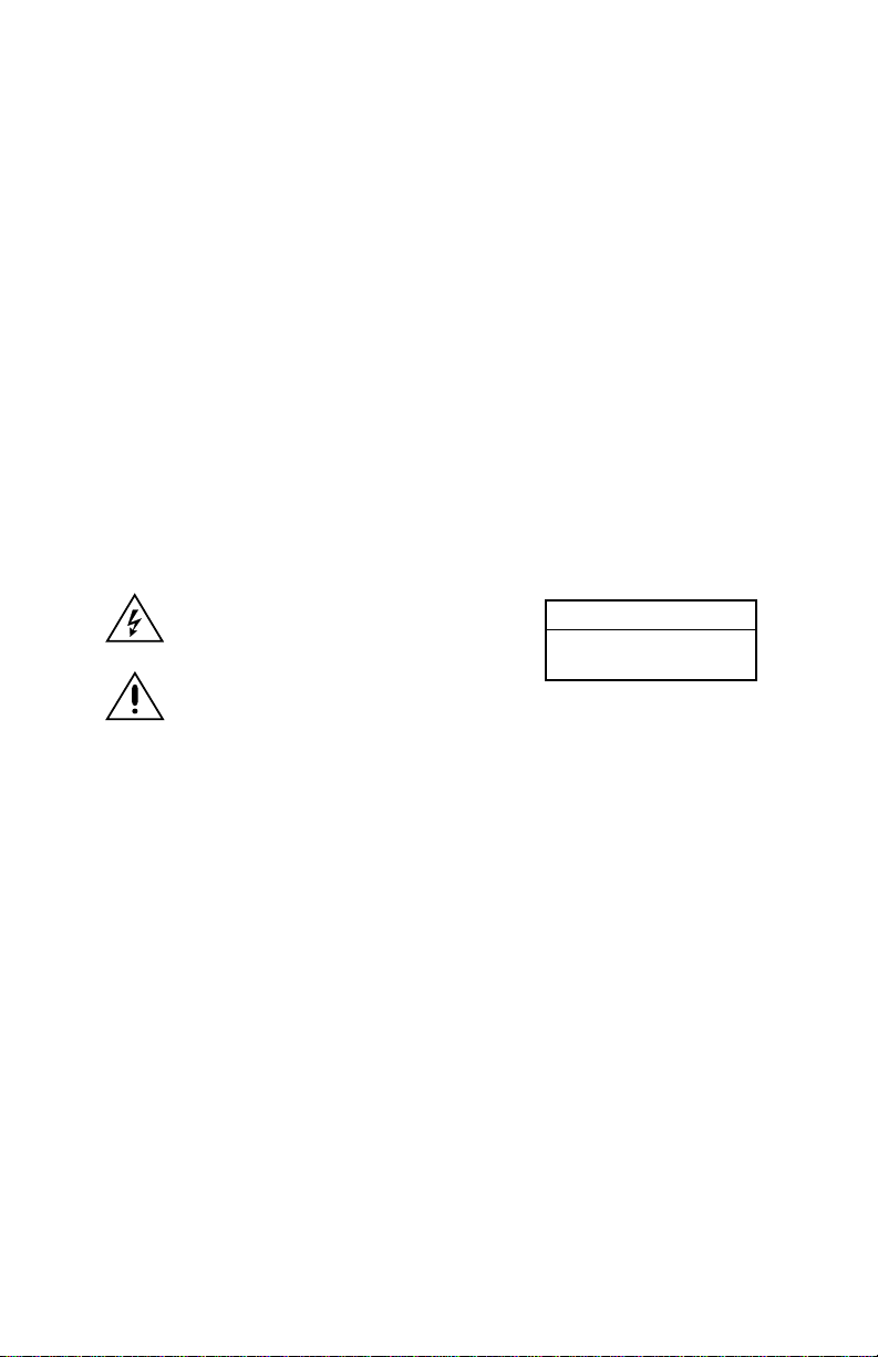
The product and/or manual may bear the following marks:
This symbol indicates that dangerous voltage constituting a risk of electric shock is present within this
unit.
This symbol indicates that there are important oper-
CAUTION:
RISK OF ELECTRIC SHOCK.
DO NOT OPEN.
ating and maintenance instructions in the literature
accompanying this unit.
Please thoroughly familiarize yourself with the information in this manual prior to installation and operation.
[
]
2
Pelco Manual C1506M (3/00)
Page 3

DESCRIPTION
The IRD/ERD2000 Series Receiver operates Pelco’s fixed speed pan/tilts and domes.
The receiver works with standard and extended Coaxitron® controllers, including the CM6700/7500/8500/
9500, KBD9000, MPT9000/9008/9500, and MX4000. With Coaxitron control, pan/tilt and lens control signals are transmitted over the video coaxial cable. The control data is superimposed on the vertical blanking interval of the video signal.
Standard features include pan/tilt control (including auto and random scan), camera power, lens control
(zoom, iris, and focus), and two auxiliary outputs. The receiver also can be used with the LRD41TLC Test
Local Control module, which allows on-site testing and troubleshooting of system functions. The TLC
module plugs into the receiver and operates off the receiver’s power.
Models
IRD2024 Indoor, fixed speed, Coaxitron receiver, 24 VAC input, 24 VAC output for camera
power and pan/tilt operation
ERD2200 Outdoor, fixed speed, Coaxitron receiver, 115/230 VAC input, 24 VAC output for cam-
era power, 24, 115, or 230 VAC output for pan/tilt operation, and 115 or 230 VAC output for enclosure accessories
MOUNTING
Attach the IRD2024 to a flat surface.
Attach the ERD2200 to a vertical surface with the conduit entries facing down. Use the housing as a template for drilling mounting holes.
Use 1/4-inch fasteners (not supplied) of the appropriate length. Refer to the illustrations below.
ANCHOR OR TOGGLE BOLT
(NOT SUPPLIED)
WOOD SCREW
(NOT SUPPLIED)
ANCHOR
(NOT SUPPLIED)
WALLBOARD
WALL
CONCRETE
WALL
Pelco Manual C1506M (3/00)
[
]
3
Page 4

ERD2200 WIRING
Input Power Enclosure Main
ERD2200 Power Connections
115 VAC 4A .5A
230 VAC 2A .25A
1. Fuses are installed for 115 VAC operation.
ENCLOSURE FUSE
MAIN
FUSE
For 230 VAC operation, install the appropriate
fuses (supplied).
230V
115V
115V
2. Set the power selector switch to either
115V or 230V to match your input power.
3. Connect main power.
POWER
SELECTOR
SWITCH
ENCLOSURE
POWER OUT
L
MAIN
POWER IN
N
L
N
The bottom of the housing has five conduit entries (fittings not supplied) to bring wiring into the receiver. Connect 115/230 VAC to the Main Power In terminals inside the receiver with AC high going
to the L (line) terminal and AC low to the N (neutral) terminal. Connect ground wire to the stud inside the housing. Do not turn on power.
4. Connect enclosure power (optional).
If you have an enclosure with heater, blower, or defroster, connect wires from
the pan/tilt or enclosure to the Enclosure Power Out terminals inside the receiver.
The enclosure must use the same power as
the receiver.
5. Set the P/T SELECT switch on the rear of the receiver according to the pan/tilt voltage requirements.
PAN/TILT VOLTAGE WARNING:
Never move the P/T SELECT switch toward the high voltage side unless you are positive
your pan/tilt requires 115/230 VAC. Inadvertently selecting the switch for high voltage will
permanently damage a 24 VAC pan/tilt.
POWER
TERMINALS
GROUND
STUD
If you select 24 VAC, the maximum output is 48 vA (supplied by the transformer inside the receiver);
make sure the combined output of your pan/tilt and camera (if it also uses 24 VAC) does not exceed
this output.
[
]
4
Pelco Manual C1506M (3/00)
Page 5

Rear View of Receiver
~
24 VAC INPUT
24 V
~
AC
P/T SELECT
115/230
~
V
AC
ERD OPTION
Front View of Receiver
VIDEO
IN OUT
TLC
~
24V
CC
PAN/TILT CAM PWR
AC
I F Z C
LENS
+
CNN
5V
AUX1 AUX2
PWR CX
CO
6. Connect the pan/tilt controls (up, down, left, right, and common).
7. Connect the camera power.
If your camera uses 24 VAC, connect the camera to the CAM PWR connector on the front of the receiver. The camera’s power must not exceed 5 vA.
If your camera uses 115 or 230 VAC, connect the camera’s power leads to the Enclosure Power Out
terminals inside the receiver. The camera’s power must be the same as the receiver’s power (Main
Power In terminals).
8. Connect the motorized lens controls (iris, focus, zoom, and common).
9. Connect video.
VIDEO IN comes from the camera.
VIDEO OUT goes to the controller.
If necessary, refer to Table B in the
Wiring Tables
section to determine appropriate coaxial cable types
for video applications.
10. Connect the auxiliary outputs (optional).
AUX 1 is a 5 VDC, 20 mA maximum, open collector output. Use the auxiliary:
• To operate low current relays
• To turn on or off a Pelco window wiper that has TTL circuitry
AUX 2 is a normally open/normally closed (Form C) relay. Relay contacts are rated at 1A maximum at
24 VDC or .5A maximum at 115 VAC.
11. Double check all wiring connections, and then turn on power.
Pelco Manual C1506M (3/00)
[
]
5
Page 6

IRD2024 WIRING
Rear View of Receiver
~
24 VAC INPUT
24 V
~
AC
P/T SELECT
115/230
~
V
AC
ERD OPTION
Front View of Receiver
VIDEO
IN OUT
TLC
~
24V
CC
PAN/TILT CAM PWR
AC
I F Z C
LENS
+
CNN
5V
AUX1 AUX2
PWR CX
CO
1. Connect power to the 24 VAC INPUT connector on the rear of the receiver. The receiver’s power requirement is a maximum of 5 vA, not including the camera and pan/tilt. Refer to the pan/tilt manual for
its power requirements. Do not turn on power.
If necessary, refer to Table A in the
Wiring Tables
section to determine appropriate wire sizes for 24
VAC applications.
2. Make sure the P/T SELECT switch on the rear of the receiver is set toward 24 VAC. The 115/230 VAC
switch position is used only with the ERD2200.
3. Connect the pan/tilt controls (up, down, left, right, and common).
4. Connect the camera power (24 VAC).
5. Connect the motorized lens controls (iris, focus, zoom, and common).
6. Connect video.
VIDEO IN comes from the camera.
VIDEO OUT goes to the controller.
If necessary, refer to Table B in the
Wiring Tables
section to determine appropriate coaxial cable
types for video applications.
7. Connect the auxiliary outputs (optional).
AUX 1 is a 5 VDC, 20 mA maximum, open collector output. Use the auxiliary:
• To operate low current relays
• To turn on or off a Pelco window wiper that has TTL circuitry
AUX 2 is a normally open/normally closed (Form C) relay. Relay contacts are rated at 1A at 24 VDC
or .5A at 115 VAC.
8. Double check all wiring connections, and then turn on power.
[
]
6
Pelco Manual C1506M (3/00)
Page 7

OPERATION
When power is applied to the receiver, the green PWR LED on the receiver lights.
Whenever the receiver gets a valid Coaxitron control signal, the green CX LED blinks.
Random/Auto Scanning
Operation of random and auto scanning depends on whether your transmitter/controller is communicating
with the IRD2000/ERD2200 in standard or extended Coaxitron mode.
Standard Coaxitron
Press the Pan Auto (or Autoscan) key to begin random scanning. In random scan operation the pan/tilt
travels between the limit stops with a random scan period of 0-60 seconds. The pan/tilt then stops for
a random period of 0-60 seconds before starting another random scan period. The direction the pan/
tilt moves when another scan period is started is also randomly determined. When a pan limit stop is
reached, scan direction reverses automatically.
Press the Pan Auto (or Autoscan) key again to start auto scanning. After approximately a half hour of
auto scanning, the pan/tilt switches to random scanning.
To turn off random/auto scanning, press the Pan Man (or Manscan) key.
Extended Coaxitron
Activate random/auto scanning by calling the following presets:
Preset 97 – Random scanning
Preset 98 – Continuous auto scanning–see WARNING below
Preset 99 – Auto scanning with half-hour timeout, after which pan/tilt switches to random scanning
Preset 96 – Stop scanning
WARNING
Activating preset 98 (continuous auto scanning) reduces the warranty on your pan/tilt to six months.
Auxiliary Operation
Operation of the two auxiliaries varies depending on the transmitter/controller you are using and whether
it is communicating in standard or extended Coaxitron mode. Refer to your transmitter/controller manual
for the exact key-press sequence required to send an Aux 1 or Aux 2 command. The following explains
how the auxiliaries respond with the different Coaxitron modes.
Standard Coaxitron
When a valid Aux 1 or Aux 2 command is received, the corresponding auxiliary operates momentarily.
Extended Coaxitron
When a valid Aux 1 or Aux 2 command is received, the corresponding auxiliary operates momentarily.
Optional Latching Mode (Extended Coaxitron Only)
Aux 3 or Aux 4 command is received, the corresponding auxiliary performs a latching operation.
NOTE:
Aux 3 operates Aux 1 and Aux 4 operates Aux 2.
– When a valid
Pelco Manual C1506M (3/00)
[
]
7
Page 8

FUSE REPLACEMENT
IRD2024
Lens/Auxiliary Fuse – A 500 mA fuse protects the LENS and AUX 1 outputs. Remove the cover
of the receiver to check the fuse.
ERD2200
Main Fuse – The main fuse protects the pan/tilt output when 24 VAC pan/tilt operation is selected. It
also protects the 24 VAC camera output. Refer to the
Enclosure Fuse – The enclosure fuse protects the pan/tilt output when 115/230 VAC pan/tilt operation is selected. It also protects the enclosure output. Refer to the
cation and values.
Lens/Auxiliary Fuse – A 500 mA fuse protects the LENS and AUX 1 outputs. Remove the cover
of the receiver inside the housing to check the fuse.
ERD2200 Wiring
section for fuse location and values.
ERD2200 Wiring
section for fuse lo-
TROUBLESHOOTING
Check the wiring connections.
If the CX LED does not blink when commands are sent to the receiver, make sure the controller is working properly. Also check the video coaxial cable between the controller and the VIDEO OUT connection
on the receiver.
An LRD41TLC Test Local Control Module is available from Pelco to test or troubleshoot your receiver,
pan/tilt, and lens functions directly from the receiver.
This lightweight, hand-held keypad tests the up, down, left, and right functions of the pan/tilt, and the iris
open/close, focus near/far, and zoom telephoto/wide functions of the lens.
1. Plug the module into the TLC connector on the front of the receiver. The module can be plugged in
with the receiver’s power turned on.
2. Push the buttons on the keypad to test your equipment. The TLC module can be used without disconnecting the receiver from the controller. The TLC module will override any signals from the controller.
[
]
8
Pelco Manual C1506M (3/00)
Page 9

WIRING TABLES
Table A
24 VAC Wiring Distances Table
The following are the recommended maximum wire distances (transformer to load) for 24 VAC applications and are calculated with a 10-percent voltage drop. (Ten percent is generally the maximum allowable
voltage drop for AC-powered devices.) Distances are calculated in feet; values in parentheses are
meters.
Wire Gauge
20 18 16 14 12 10
10 283 (86) 451 (137) 716 (218) 1,142 (348) 1,811(551) 2,880 (877)
20 141 (42) 225 (68) 358 (109) 571 (174) 905 (275) 1,440 (438)
30 94 (28) 150 (45) 238 (72) 380 (115) 603 (183) 960 (292)
40 70 (21) 112 (34) 179 (54) 285 (86) 452 (137) 720 (219)
50 56 (17) 90 (27) 143 (43) 228 (69) 362 (110) 576 (175)
60 47 (14) 75 (22) 119 (36) 190 (57) 301 (91) 480 (146)
70 40 (12) 64 (19) 102 (31) 163 (49) 258 (78) 411 (125)
80 35 (10) 56 (17) 89 (27) 142 (43) 226 (68) 360 (109)
90 31 (9) 50 (15) 79 (24) 126 (38) 201 (61) 320 (97)
100 28 (8) 45 (13) 71 (21) 114 (34) 181 (55) 288 (87)
110 25 (7) 41 (12) 65 (19) 103 (31) 164 (49) 261 (79)
Total vA consumed
120 23 (7) 37 (11) 59 (17) 95 (28) 150 (45) 240 (73)
130 21 (6) 34 (10) 55 (16) 87 (26) 139 (42) 221 (67)
140 20 (6) 32 (9) 51 (15) 81 (24) 129 (39) 205 (62)
150 18 (5) 30 (9) 47 (14) 76 (23) 120 (36) 192 (58)
EXAMPLE: An enclosure that requires 80 vA and is installed 35 feet (10 m) or less from the 24 VAC source
would require a minimum wire gauge of 20 AWG.
Table B
Video Coaxial Wiring Distances
Cable Type* Maximum Distance
RG59/U 750 ft (229 m)
RG6/U 1,000 ft (305 m)
RG11/U 1,500 ft (457 m)
* Minimum cable requirements:
75 ohms impedance
All-copper center conductor
All-copper braided shield with 95% braid coverage
Pelco Manual C1506M (3/00)
[
]
9
Page 10

SPECIFICATIONS
ERD2200
ELECTRICAL
Input Voltage: 115/230 VAC, 50/60 Hz
Output Voltage
Camera: 24 VAC (or 115/230 VAC if using
Lens: 8 VDC
Pan/Tilt: 24/115/230 VAC
Enclosure: 115/230 VAC
Power Consumption
Receiver: 5 vA maximum
Pan/Tilt and
Camera: 48 vA maximum at 24 VAC (includes
Fuses
Main: 115 VAC – .5A 230 VAC – .25A
Enclosure: 115 VAC – 4A 230 VAC – 2A
Lens/Aux 1: .5A
Video Input/
Output: 75 ohms
Video
Bandwidth: 10 MHz
Video Gain: Unity
Video Formats: NTSC or PAL
Control
Method: Standard or extended Coaxitron
Auxiliary
Outputs: One open collector, TTL
MECHANICAL
Video
Connectors: BNC
P/T, Camera,
Auxiliary,
Lens, Power
Connectors: Screw terminals
Cable Entry: Openings for .75-inch (1.91 cm)
GENERAL
Environment: Outdoor
Construction: Aluminum (receiver),
Finish: Gray polyester powder coat
Operating
Temperature: -50° to 122°F (-46° to 50°C)
Dimensions: 15.2 (L) x 12.2 (W) x 5.0 (H) inches
Weight: 9.90 lb (4.50 kg)
CERTIFICATIONS/RATINGS
CE, Class A
UL, cUL pending
NEMA 4, IP 66 pending
[
]
10
Pelco Manual C1506M (3/00)
enclosure power)
5 vA maximum for camera)
One N.O./N.C. (Form C) relay
conduit
steel (housing)
(38.6 x 31.0 x 12.7 cm)
IRD2024
ELECTRICAL
Input Voltage: 24 VAC, 50/60 Hz
Output Voltage
Camera and
Pan/Tilt: 24 VAC
Lens: 8 VDC
Power Consumption
Receiver: 5 vA maximum
Fuse
Lens/Aux 1: .5A
Video Input/
Output: 75 ohms
Video
Bandwidth: 10 MHz
Video Gain: Unity
Video Formats: NTSC or PAL
Control
Method: Standard or extended Coaxitron
Auxiliary
Outputs: One open collector, TTL
One N.O./N.C. (Form C) relay
MECHANICAL
Video
Connectors: BNC
P/T, Camera,
Auxiliary,
Lens, Power
Connectors: Screw terminals
GENERAL
Environment: Indoor
Construction: Aluminum
Finish: Black polyester powder coat
Operating
Temperature: -10° to 122°F (-23° to 50°C)
Dimensions: 10.3 (L) x 6.0 (W) x 1.75 (H) inches
(26.2 x 15.2 x 4.4 cm)
Weight: 1.25 lb (0.58 kg)
CERTIFICATIONS/RATINGS
CE, Class A
UL, cUL pending
NEMA 1, IP 10 pending
(Design and product specifications subject to change without notice.)
Page 11

Pelco Manual C1506M (3/00)
[
11
]
Page 12

WARRANTY AND RETURN INFORMATION
WARRANTY
Pelco will repair or replace, without charge, any merchandise proved defective in material or workmanship for a period of one year after the
date of shipment. Exceptions to this warranty are as noted below:
• Three years on Genex® Series (multiplexers, server, and keyboard).
• Two years on cameras and all standard motorized or fixed focal length lenses.
• Two years on Legacy®, Camclosure™ Camera Systems, CM6700/CM8500/CM9500/CM9750/CM9760 Matrix, PelcoVision® , DF5 Series,
and DF8 Fixed Dome products.
• Two years on Spectra® and Esprit™, including when used in continuous motion applications.
• Two years on WW5700 series window wiper (excluding wiper blades).
• Six months on all pan and tilts, scanners or preset lenses used in continuous motion applications (that is, preset scan, tour and auto
scan modes).
Pelco will warrant all replacement parts and repairs for 90 days from the date of Pelco shipment. All goods requiring warranty repair shall be
sent freight prepaid to Pelco, Clovis, California. Repairs made necessary by reason of misuse, alteration, normal wear, or accident are not
covered under this warranty.
Pelco assumes no risk and shall be subject to no liability for damages or loss resulting from the specific use or application made of the Products. Pelco’s liability for any claim, whether based on breach of contract, negligence, infringement of any rights of any party or product liability, relating to the Products shall not exceed the price paid by the Dealer to Pelco for such Products. In no event will Pelco be liable for any
special, incidental or consequential damages (including loss of use, loss of profit and claims of third parties) however caused, whether by the
negligence of Pelco or otherwise.
The above warranty provides the Dealer with specific legal rights. The Dealer may also have additional rights, which are subject to variation
from state to state.
If a warranty repair is required, the Dealer must contact Pelco at (800) 289-9100 or (559) 292-1981 to obtain a Repair Authorization number
(RA), and provide the following information:
1. Model and serial number
2. Date of shipment, P.O. number, Sales Order number, or Pelco invoice number
3. Details of the defect or problem
If there is a dispute regarding the warranty of a product which does not fall under the warranty conditions stated above, please include a written explanation with the product when returned.
Method of return shipment shall be the same or equal to the method by which the item was received by Pelco.
RETURNS
In order to expedite parts returned to the factory for repair or credit, please call the factory at (800) 289-9100 or (559) 292-1981 to obtain an
authorization number (CA number if returned for credit, and RA number if returned for repair). Goods returned for repair or credit should be
clearly identified with the assigned CA/RA number and freight should be prepaid. All merchandise returned for credit may be subject to a
20% restocking and refurbishing charge.
Ship freight prepaid to: Pelco
300 West Pontiac Way
Clovis, CA 93612-5699
REVISION HISTORY
Manual # Date Comments
C1506M 3/00 Original version.
® Pelco, the Pelco logo, Spectra, Genex, Legacy, and PelcoVision are registered trademarks of Pelco. © Copyright 2000, Pelco.
™ Esprit and Camclosure are trademarks of Pelco. All rights reserved.
 Loading...