

Page 1

ADDENDUM
Addendum No.: C1577M-A
Date: August 4, 2004
Manuals Affected: CM9760 Series Manuals – C538M-A, C539M-A, C540M-B, C541M-C, C542M-B,
C543M-A, C544M, C549M-A, C572M, C573M-D, C578M, C579M, C1501M, C1503M,
C1510M-QS, C1510M-A, C1520M-B, C1528M-D, C1940M, C1941M, C1942M, and
C1943M
Manual Update: The CM9760-CC1 has been replaced with the CM9700-CC1 and the CM9760-MGR manage-
ment software has been replaced with the CM9700-MGR management software.
Keep the following in mind when referring to the instructions contained in these manuals:
• The CM9700-CC1 contains the latest CC1 software (version 9.01 or higher), and is
programmed with the new CM9700-MGR management software.
• Despite the difference in model numbers, the CM9700-CC1 functions the same as the
CM9760-CC1 and most of the information in these manuals applies to version 9.01 (or
higher) CPU.
•You can add the CM9700-CC1 to an existing CM9760 system if you upgrade the existing
CM9760-CC1 units with the current software (version level 9.01 or higher).
Software version 9.01 requires a minimum of 16 MB of RAM in the CPU. If required, you
can upgrade the RAM in older CM9760-CC1 units using the software upgrade kit
appropriate for your CPU.
• Do not use the CM9760-MGR instructions contained in these manuals. Refer to the
CM9700-MGR Getting Started Software Guide, on-screen help, or Online Help for
instructions.
Pelco World Headquarters • 3500 Pelco Way, Clovis, California 93612-5699 USA • www.pelco.com
USA & Canada: Tel: 800/289-9100 • Fax: 800/289-9150
®
International: Tel: 1-559/292-1981 • Fax: 1-559/348-1120
Page 2

®
System 9760
®
Installation Guide
C1503M (11/99)
Pelco • 300 W. Pontiac Way, Clovis • CA 93612-5699 USA • Pelco Online @ http://www.pelco.com
In North America and Canada: Tel (800) 289-9100 or FAX (800) 289-9150 • DataFAX (800) 289-9108
International Customers: Tel +1 (559) 292-1981 or FAX +1 (559) 348-1120 • DataFAX +1 (559) 292-0435
Page 3

CONTENTS
Section Page
SYSTEM UNPACKING AND RACKING .............................................................................3
SYSTEM DATA CONNECTIONS .......................................................................................4
ADDITIONAL HOOKUP INFORMATION ........................................................................... 5
SYSTEM VIDEO CONNECTIONS .....................................................................................5
DEFINITIONS ............................................................................................................5
VIDEO INPUTS ..........................................................................................................5
SINGLE-BAY SYSTEMS ....................................................................................5
MULTI-BAY SYSTEMS ......................................................................................6
VIDEO OUTPUTS ......................................................................................................6
NETWORKING ..........................................................................................................6
SYSTEM PROGRAMMING................................................................................................6
CM9760-MGR ............................................................................................................6
SET 9750 ................................................................................................................... 6
DOS ...................................................................................................................................7
FILE MAINTENANCE ........................................................................................................7
TRANSFER FILES FROM CM9760-CC1 TO CM9760-MGR .................................... 7
TRANSFER FILES FROM CM9760-MGR TO 3.5-INCH FLOPPY DISK ................... 7
TRANSFER FILES FROM 3.5-INCH FLOPPY DISK TO CM9760-CC1 ....................8
RENAMING CONFIGURATION FILES ......................................................................8
VERIFYING OPERATION ..................................................................................................9
APPENDIX .........................................................................................................................9
SYSTEM PORT SETTINGS TABLE ........................................................................... 9
SETUP DRAWINGS.................................................................................................. 11
TYPICAL CONNECTIONS ............................................................................... 11
WARRANTY AND RETURN INFORMATION ................................................................... 40
LIST OF ILLUSTRATIONS
Figure Page
1 CM9760-CC1 Typical Port Layout .....................................................................11
2 CM9760-MXB Typical Connections...................................................................11
3 496 X 16 ............................................................................................................ 12
4 496 X 16 Looping ..............................................................................................13
5 736 X 16 ............................................................................................................ 14
6 736 X 16 Looping ..............................................................................................14
7 976 X 16 ............................................................................................................ 15
8 976 X 16 Looping ..............................................................................................16
9 496 X 32 ............................................................................................................ 17
10 496 X 32 Looping ..............................................................................................18
11 736 X 32 ............................................................................................................ 19
12 736 X 32 Looping ..............................................................................................20
13 976 X 32 ............................................................................................................ 21
14 976 X 32 Looping ..............................................................................................22
15 256 X 48 ............................................................................................................ 23
16 256 X 48 Looping ..............................................................................................24
17 496 X 48 ............................................................................................................ 25
18 496 X 48 Looping ..............................................................................................26
19 736 X 48 ............................................................................................................ 27
20 736 X 48 Looping ..............................................................................................28
21 976 X 48 ............................................................................................................ 29
22 976 X 48 Looping ..............................................................................................30
23 256 X 64 ............................................................................................................ 31
24 256 X 64 Looping ..............................................................................................32
25 496 X 64 ............................................................................................................ 33
26 496 X 64 Looping ..............................................................................................34
27 736 X 64 ............................................................................................................ 35
28 736 X 64 Looping ..............................................................................................36
29 976 X 64 ............................................................................................................ 37
30 976 X 64 Looping ..............................................................................................38
2 Pelco Manual C1503M (11/99)
Page 4

This guide is intended to help you with the basic installation and setup of the Pelco System
9760® Matrix Switcher and Controller. This guide is not a replacement for the system
manual, but rather a tool to help you quickly get the system up and running.
Before shipping, Pelco sets up, tests, and programs each system according to the individual
sales order. As a first step, verify that the packing slip corresponds to your sales order. Contact
us immediately if there is a discrepancy.
This guide covers the following:
1. System Packing and Racking
2. System Data Connections
• CM9760-CC1 System CPU
• CM9760-MXB Matrix Bays
• CM9760-KBD System Keyboards
• CM9760-MGR Manager Program
• Receiver Connections
• CM9760-NW1
• Peripheral Equipment
3. System Video Connections
• Definitions
• Video Inputs
• Down-Framing Interconnections
• Side-Framing Interconnections
• Video Outputs
• Networking
4. System Programming
• Manager Program
• SET 9750 Program
5. DOS
6. File Maintenance
• Transfer Files from CM9760-CC1 to CM9760-MGR
• Transfer Files from CM9760-MGR to 3.5-Inch Floppy Disk
• Transfer Files from 3.5-Inch Floppy Disk to CM9760-CC1 Hard Drive
• Renaming Configuration Files
7. Verifying Operation
8. Appendix
• System Port Settings Table
• Setup Drawings
SYSTEM UNPACKING AND RACKING
1. Unpack and inspect all equipment and verify delivery according to the packing slip.
2. Remove and save all manuals and cabling from all packages and keep them with their
associated equipment.
3. Locate in your documentation the following:
• The page entitled System 9760 Factory Default Port Settings. This im-
portant document contains specific information about your system. All System
9760s are pre-programmed based on specific criteria in the system order.
• System 9760 manual binders.
4. For best results and a clean installation, install the System 9760 using standard EIA
19-inch racks. Leave one rack unit space between each card cage for effective cooling.
5. Review the sample drawings in the appendix and select the configuration that most
closely resembles the system you are installing.
Pelco Manual C1503M (11/99) 3
Page 5

6. Install the system CM9760-CC1 CPU and CM9760-MXB matrix bays near each other.
Note that each CM9760-MXB has a unique label for identifying the bay location in the
installation. This ID information is important in ensuring correct video and data connections.
7. Install any system peripherals in a convenient location.
8. Locate the CM9760-KBD system keyboard(s), CM9505-UPS power supply(s), and the
two RJ-45 data cables supplied with each keyboard.
9. Connect all power line cords to the equipment. Do not apply power to the equip-
ment at this time.
SYSTEM DATA CONNECTIONS
1. CM9760-CC1
This is the main system controller, often called the CPU.
a. Copy the supplied system port settings from the System 9760 Factory Default
Port Settings to the System Port Settings Table in the appendix of this installation
guide.
b. Enter the label information from each matrix bay in the Description section (to
avoid confusion after completing the installation).
c. Update this table as the installation proceeds.
2. CM9760-MXB
This is the video matrix (switching) bay that contains the video input, output modules,
and bay controller module.
a. Follow the System Port Settings Table and connect the CM9760-CC1 to the
CM9760-MXB bays using the supplied RJ-45 data cables.
b. Be sure to match the matrix bay label to the CM9760-CC1’s port.
3. CM9760-KBD
This is the system keyboard for operator control commands.
a. Locate the RJ-45 data cable labeled “STRAIGHT.” Connect one end to the COM1
input on the bottom of the keyboard; connect the other end to the KEYBOARD input on the CM9505-UPS power supply.
b. Locate the cable labeled “REVERSED.” Identify the keyboard on the System Port
Settings Table. Connect one end of this cable to the appropriate data port on the
CM9760-CC1; connect the other end to the CARD CAGE input on the CM9505UPS.
4. External PC/CM9760-MGR
The CM9760-CC1 provides two 9-pin sub-miniature D connectors used for standard
RS-232 communications with the CPU. COM1 is set at the factory for use with the
CM9760-MGR program used for system programming.
a. Connect one end of a standard 9-pin sub-D cable (not supplied) to the CM9760-
CC1 and the other end to the external PC.
b. Be sure the Com port settings on the PC match the settings for COM1 on the
CM9760-CC1.
c. Refer to the
ministrative Software Manual.
Hardware Installation
section in the CM9760-MGR System 9760 Ad-
4 Pelco Manual C1503M (11/99)
Page 6

ADDITIONAL HOOKUP INFORMATION
• Comms File
The Comms Setup File contains information about the equipment that is attached to
your system. Access the Comms dialog box by clicking on the Comms tab in the Setup
9760 Configuration dialog box. Refer to the
the CM9760-MGR System 9760 Administrative Software Manual for information.
• Pan And Tilt Receivers and Domes
Each port can have up to 16 receivers or domes when using hardwired RS-422 communications connected in a daisy chain configuration.
• Ports
Use the System Port Settings Table to determine which ports are not in use. When setting up pan and tilt devices for use with the System 9760, edit the Comms file using
Pin #9 as the equipment number. Be sure the assigned port’s baud rate and parity
match that of the pan and tilt receiver. Refer to the
tion in the CM9760-MGR System 9760 Administrative Software Manual.
• Peripheral Equipment
Refer to the specific user manual for a description of each device. An RJ-45 data cable
is included with each device. Using the Factory Default Port Settings page and the
device’s interconnect cable, connect all peripheral equipment to its appropriate data
port. If the device is not shown on the Factory Default Port Settings page, refer to the
major section
CM9760-MGR System 9760 Administrative Software Manual. Also, refer to
puts
and
puts.
• CM9760-NW1
This CPU serves as a communications hub when networking two or more System
9760s. This unit includes its own Factory Default Settings table. Use both tables to determine which ports are used for data interconnection between the CM9760-CC1s and
the CM9760-NW1.
Configuring the System 9760 with the Pelco Window Set 9760
Video Outupts
sections for information on connecting video sources and out-
Comms Setup File (.SCP File)
Comms Setup File (.SCP File)
section in
sec-
in the
Video In-
SYSTEM VIDEO CONNECTIONS
For best results, use crimp-on BNCs only. Do not use screw-on BNCs–these typically do
not provide adequate ground and signal connections.
DEFINITIONS
Bay Capacity: A single CM9760-MXB can support up to 256 inputs (in increments of
Side Framing: A technique to expand the matrix video inputs beyond 256.
Down Framing: A technique to expand the matrix video outputs beyond 16.
Video Tie Lines: A method for connecting side-framed matrix bays together and networked
VIDEO INPUTS
SINGLE-BAY SYSTEMS
Refer to the sample drawings in the appendix. Connect all video sources (cameras, VCRs,
etc.) to the video input BNCs at the rear of the CM9760-MXB(s). Connect video 1 to the BNC
marked “1,” video 2 to the second BNC directly below “1,” and so on until all video cables
are connected. If the system is set up for looping, terminate the looped output at 75 ohms.
16) and 16 outputs (in increments of 4).
systems together. A video tie line is a video output from one bay connected to the video input of another. In a networked system, a tie line
provides the video path necessary to view video from a remote node.
Pelco Manual C1503M (11/99) 5
Page 7

MULTI-BAY SYSTEMS
1. Down-Framing – For systems with more than 16 monitor outputs, you must pas-
sively loop the video from the first CM9760-MXB to the second CM9760-MXB for the
next 16 monitors. The best location for the second bay is below the first bay, as shown
in the system drawing. Connect the supplied multi-coax ribbon cable from the bottom
of the first bay to the down-frame loop input of the second. Continue in this manner
connecting all down-framing bays.
2. Video-Looping – If your system is configured for video looping, properly terminate
the video cable at the last connection with 75 ohm.
3. Side-Framing – For systems with more than 256 video inputs, connect the 16 video
outputs from the second matrix bay to the first 16 video inputs of the first bay. The best
location for the second bay is next to the first bay on the same level, as shown in the
system drawing. Continue in this manner connecting all side-framing bays.
VIDEO OUTPUTS
Connect all video outputs from the CM9760-MXB to their desired device (that is, monitors,
printers, VCRs, etc.). Terminate the device at 75 ohms.
NETWORKING
For networked systems, refer to the system drawing to determine which monitor outputs
and camera inputs were assigned as video tie lines. Connect the monitor outputs assigned
as tie lines of one system to the video inputs assigned as tie lines of the other, and vice
versa.
SYSTEM PROGRAMMING
WARNING:
the Windows
manager program
(CM9760-MGR) is used to
create or edit configuration
files, the SET 9750 program
cannot be used. In other
words, the System 9760MGR flat files are not
backward compatible with
SET 9750.
After
Apply power to the CM9760-CC1, keyboard, monitor, and PC (as appropriate to the method
of programming) for system programming.
The two methods of programming the CM9760 system are as follows:
CM9760-MGR
This is the preferred programming method. It requires an external IBM-compatible PC running Windows® 95 and the supplied CM9760-MGR Manager Program. Pelco recommends
using an AT-type keyboard and VGA monitor. All system programming can be done off-site
and later downloaded (transferred) to the CM9760-CC1 by writing flat files (see the
section for an explanation of flat files). Or you can do direct “live” programming through an
RS-232 connection between the PC and the CM9760-CC1. See the
MGR Software
for details on installing the CM9760-MGR program.
The sections
CM9760-MGR to 3.5-Inch Floppy Disk
CM9760-CC1
SET 9750
This is the second programming method. The DOS-based SET 9750 program on the
CM9760-CC1 hard drive requires a VGA monitor and AT-type keyboard connected directly
to the CM9760-CC1. See the
9760
section in the CM9760-MGR System 9760 Administrative Software Manual.
DOS
section in the CM9760-MGR System 9760 Administrative Software Manual
Transfer Files from CM9760-CC1 to CM9760-MGR, Transfer Files from
that follow in this document pertain to this method.
Configuring the System 9760 with the Pelco Windows SET
, and
Transfer Files from 3.5-Inch Floppy Disk to
Installing the 9760-
6 Pelco Manual C1503M (11/99)
Page 8

DOS
The CM9760 system’s program runs in DOS. Therefore, you will need to use basic DOS
commands to transfer, overwrite, and edit data, and to maintain files on your hard drive.
The default configuration files on the CM9760-CC1 hard drive are defined at the factory and
are labeled “TEST.” These files are referred to as “flat files” and are loaded into memory
when you power up the system. (See the
dows SET 9760
for details.)
The procedures that follow show you how to copy your configuration files from the CM9760CC1 to the PC where the CM9760-MGR program is located and back again using a floppy
disk. You will need to use these procedures if you want to change these files. If you want to
rename these files, you will need to use the procedure in the
section below.
FILE MAINTENANCE
TRANSFER FILES FROM CM9760-CC1 TO CM9760-MGR
Before you can use the CM9760-MGR program to edit the pre-programmed TEST files, you
must load these files into the CM9760-MGR database.
1. Take the CM9760 offline by simultaneously pressing Ctrl and Q on the AT keyboard.
The VGA screen will display C:/9760>.
section in the CM9760-MGR System 9760 Administrative Software Manual
Configuring the System 9760 with the Pelco Win-
Renaming Configuration Files
NOTE:
The password is
case sensitive.
2. Insert a blank 3.5-inch floppy disk into the floppy drive of the CM9760-CC1.
3. Type copy test.* a: and press Enter. The flat files will be copied from the CM9760-
CC1 hard drive to the 3.5-inch floppy disk.
4. Remove the floppy disk and insert it into the PC that contains the CM9760-MGR program.
5. Start the manager program on the PC by double clicking on the Pelco 9760MGR
icon. Enter a user ID and password in the Log On dialog box (the default for both is
Admin
).
6. Click on the Read File icon on the taskbar. This opens the Flat File Utility – Read
dialog box. All the generated files have check marks to show they are selected.
7. Click Select on the Flat File Source button. This starts the standard Open dialog box.
8. Select Drive a:, then double click on the test.scp file to select. This closes the
Open dialog box and returns you to the Flat File Utility – Read dialog box.
9. Enter the number of the node you are using (number of the port on the NIU to which
the node is connected). Enter 1 if you only have a single node system.
10. Click on the Start button. Several warnings may appear indicating certain files do not
exist. This is okay. Select Continue Installation for each.
11. The message “Finished Reading Flat Files” appears when file transfer is complete.
TRANSFER FILES FROM CM9760-MGR TO 3.5-INCH FLOPPY DISK
This procedure is VERY IMPORTANT. You must copy flat files from the CM9760-
MGR program to a 3.5-inch floppy disk when modifying comms setup files and macro files.
1. Double click on the Pelco 9760MGR icon to start the CM9760-MGR program. Enter
a user ID and case sensitive password in the Log On dialog box (default for both is
Admin).
Pelco Manual C1503M (11/99) 7
Page 9

2. Insert a 3.5-inch floppy disk into the PC. Select the Write File icon on the task bar.
This opens the Flat File Utility – Write dialog box. The default for writing flat files is to
generate all files regardless of whether or not they are used. To write only specific files,
deselect the ones you do not want to generate.
3. Click Select on the Flat File Source button. This opens the standard Open dialog box.
4. Double click on the file you want to copy. This opens the Save As dialog box.
5. Select Drive a:. Click the SAVE tab. This returns you to the Flat File Utility – Write
dialog box.
6. Click on the Start button.
7. The “Finished Writing Flat Files” message appears when file copying ends.
TRANSFER FILES FROM 3.5-INCH FLOPPY DISK TO CM9760-CC1
The following example uses “test” as the default file name. If you have changed the configuration files name (refer to the
new name you selected instead of “test”.
1. Insert the 3.5-inch floppy disk containing the flat files you want to load into the
CM9760-CC1.
2. Take the CM9760 offline by simultaneously pressing Ctrl and Q on the AT keyboard.
The VGA monitor will display C:/9760>.
Renaming Configuration Files
section below), substitute the
NOTE:
Before the files are
copied to the CM9760-CC1
hard drive, the message
“Files Already Exist, Over
Write? Y/N/A” (yes/no/all)
will appear.
SAVE
all
current operating flat files
that are being replaced
before selecting “yes” or “all”
at the prompt.
3. Type copy a: test.* and press Enter.
4. Type A to the prompt and press Enter. The files on the floppy disk will replace those
on the hard drive.
5. Remove the floppy disk and re-boot by simultaneously pressing Ctrl/Alt/Delete.
Changes take effect after all configuration files load.
RENAMING CONFIGURATION FILES
The
Renaming Configuration Files
name.
The system loads the flat files listed in the system’s C:/9760 subdirectory. The default
test.bat file’s command line reads
files that load when the system boots from the autoexec.bat file.
1. Take the CM9760 offline by simultaneously pressing Ctrl and Q on the CM9760 AT
keyboard. The VGA monitor will display C:/9760>.
2. Type ren test.*
you choose for the TEST files. Remember to enter a space after the first asterisk.)
3. Type cd.. to switch to the root directory.
4. Type edit autoexec.bat and press Enter. This opens the file editor and the
autoexec.bat file. The following is an example of the default autoexec.bat:
newfilename
section will show you how to give these files a new
CM9760 TEST
.* and press Enter. (
where TEST is the name of the default
“newfilename”
is any new name
echo off
path c:\dos
prompt=$t $d $p$g
uptimer /t /p /f
CD 9760
TEST
➝
(change to
newfilename
)
8 Pelco Manual C1503M (11/99)
Page 10

5. Change the command line in the autoexec.bat file to reflect the new flat files name:
from TEST to
6. Click File, then Save.
7. You also need to change the test.bat file to reflect the new flat files name, otherwise
the system will not run. Click File, then Open.
newfilename
(the name you chose in step 2 above).
8. Click on
9. Change the command line in the
from CM9760 TEST to CM9760
10. Click File, then Save.
11. Click File, then Exit to leave the file editor.
12. Re-boot the system (by simultaneously pressing Ctrl/Alt/Delete) for the changes to
take effect.
newfilename
VERIFYING OPERATION
1. Power up all the remaining equipment. After the CM9760-CC1 loads the configuration
files, the CM9760-KBD LCD should show “SYSTEM 9760.”
2. Enter 1111 (the keyboard #1 default password) on the CM9760-KBD keypad. The as-
terisks on the keyboard will move one space to the left for each number entered. The
LCD will display “ENTER MONITOR #.”
3. Enter 1 MON.
4. Press the FWD key to step through the cameras and verify switching.
The default password for keyboard 2 is 2222, keyboard 3 is 3333, etc.
APPENDIX
.bat in the 9760 directory, then Ok.
newfilename
newfilename
.bat file to reflect the new flat files name:
(the name you chose in step 2 above).
SYSTEM PORT SETTINGS TABLE
See the following page.
Pelco Manual C1503M (11/99) 9
Page 11
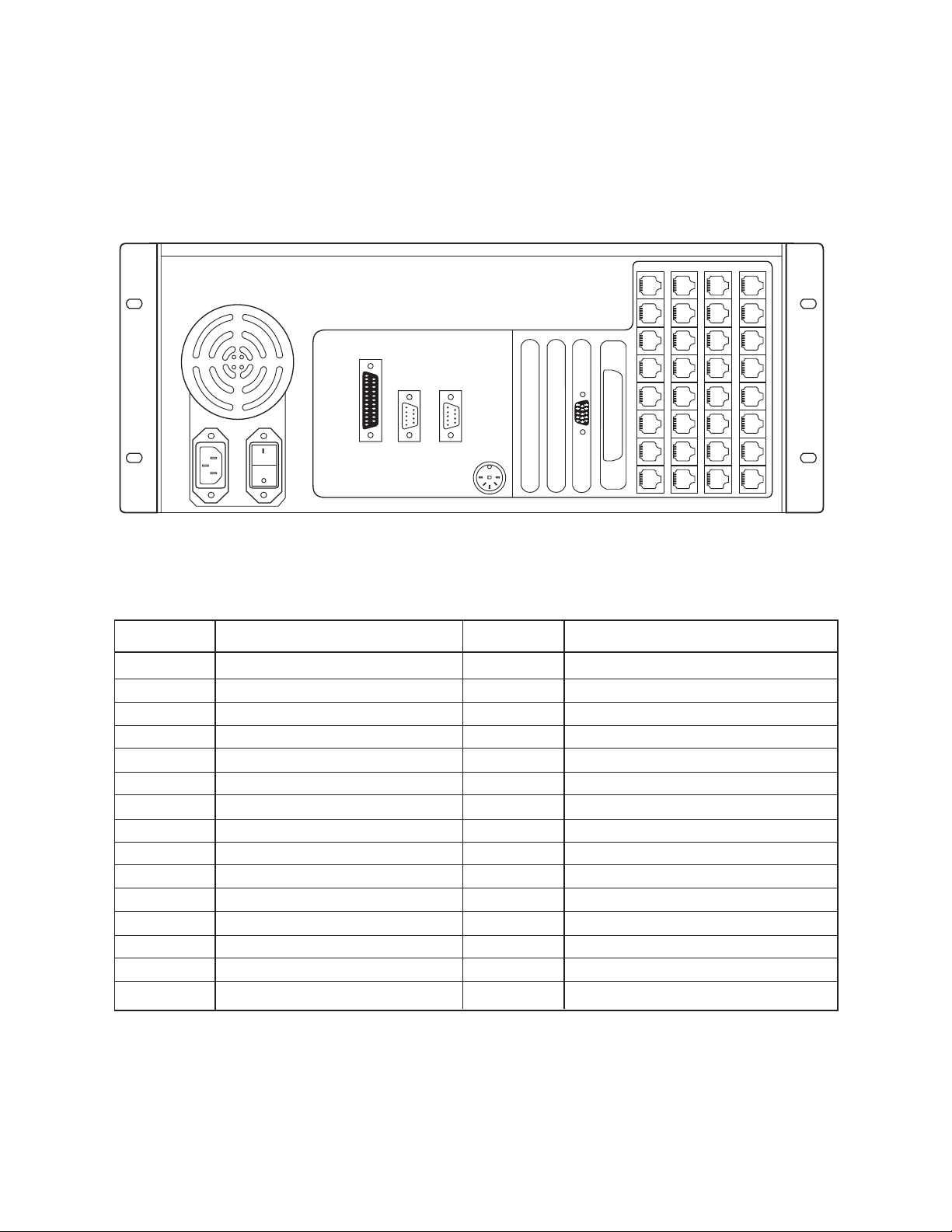
System 9760 Factory Default Port Settings
PRINTER COM1 COM2
36
35
34
33
32
31
30
29
20
28
27
26
25
24
23
22
21
12
19
11
10
18
9
17
16
8
15
7
6
14
13
5
Note: The number of ports on your system may differ from the
above drawing. Connect System 9760 components as follows:
PORT DESCRIPTION DESCRIPTIONPORT
1 (RS-232)
2 (RS-232)
3
4
NOT PRESENT
NOT PRESENT
5
6
9
10
11
12
13
15
16
17
18
FORM 1957 REVISION B (9/23/98)
19
20
21
22
23
26
27
29
30
31
32
33
24
35
36
10 Pelco Manual C1503M (11/99)
Page 12
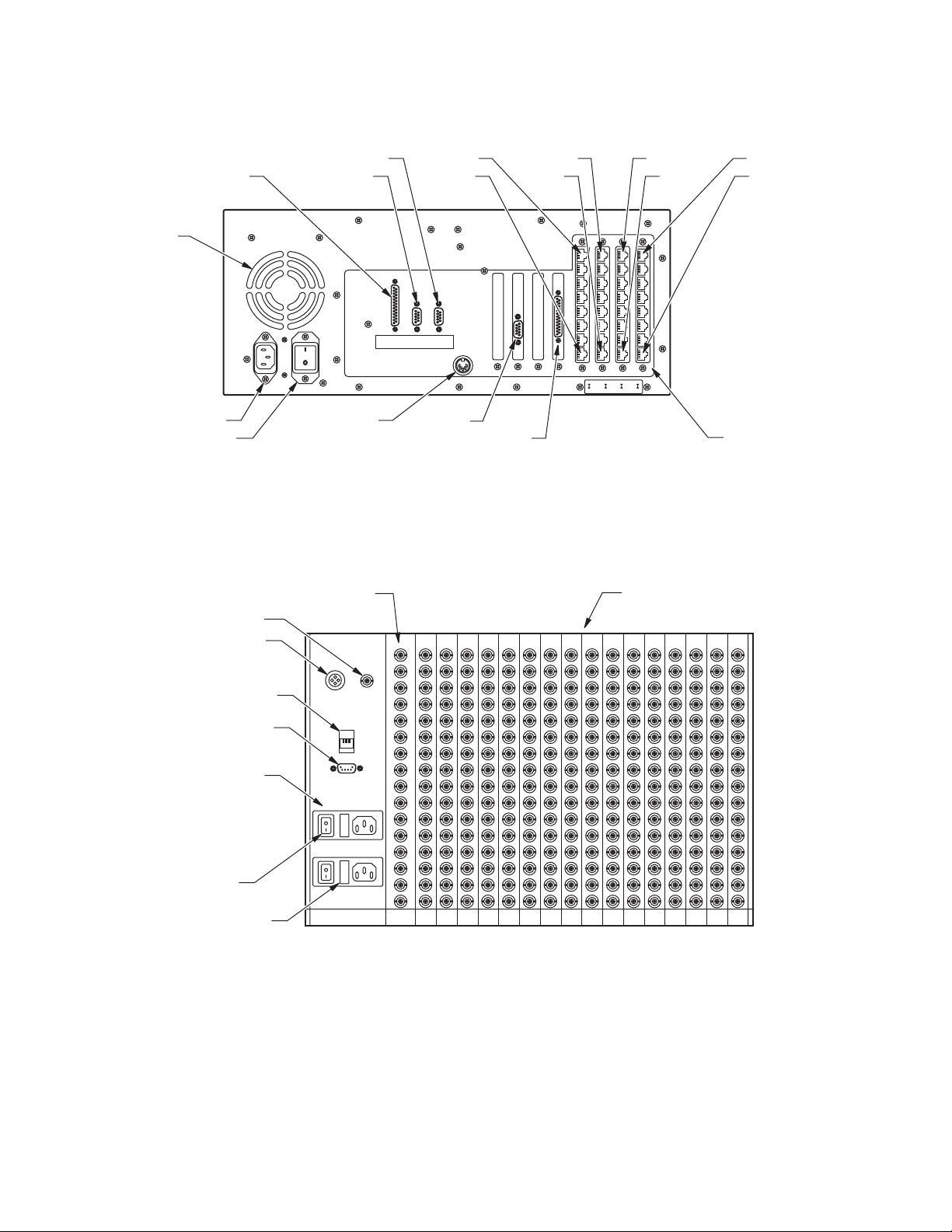
SETUP DRAWINGS
LPT PRINTER PORT
RS-232 PORT 1
FAN
POWER INPUT
AT KEYBOARD PORT
POWER SWITCH
TYPICAL CONNECTIONS
16 MONITOR OUTPUTS 256 VIDEO INPUTS
VIDEO BLACK
LEVEL OUT
ALARM PORT
RS-232 PORT 2 PORT 36
PORT 29
PRINTER COM1 COM2
PORT 28
PORT 21
VGA PORT
OPTIONAL RELAY PORT
Figure 1. CM9760-CC1 Typical Port Layout
Alarm Black
Out
35292821201312
5
PORT 20
PORT 13
PORT 12
PORT 5
RS-422 PORTS
RJ-45 DATA PORT
DB9 DATA PORT
DUAL POWER
SUPLIES
POWER
SWITCH
SUPPLY FUSES
RS-422
RS-422
Figure 2. CM9760-MXB Typical Connections
Pelco Manual C1503M (11/99) 11
Page 13
16 1
481 257 241 1
CM9760-CC1
PRINTER COM1 COM2
35292821201312
REFER TO PORT
ASSIGNMENT PAGE
FOR YOUR SYSTEM’S
SPECIFIC DATA
CONNECTIONS
5
Alarm Black
RS-422
RS-422
Out
CAMS
257-496
Alarm Black
RS-422
RS-422
Out
CM9760-MXB CM9760-MXB
Figure 3. 496 X 16
CAMS
1-256
12 Pelco Manual C1503M (11/99)
Page 14

16 1
481 257 241 1
CM9760-CC1
PRINTER COM1 COM2
35292821201312
REFER TO PORT
ASSIGNMENT PAGE
FOR YOUR SYSTEM’S
SPECIFIC DATA
CONNECTIONS
5
Alarm Black
RS-422
RS-422
Out
CAMS
Alarm Black
RS-422
RS-422
Out
257-496
CM9760-MXB CM9760-MXB
Alarm Black
RS-422
RS-422
Out
CAMS
Alarm Black
RS-422
RS-422
Out
257-496
OUT
CM9760-MXBL CM9760-MXBL
CAMS
1-256
CAMS
1-256
OUT
SUPPLIED DOWNFRAMING CABLES
16X RIBBON COAXIAL
CAM 1 LOOP-OUT
SYSTEM LOOPED
OUTPUTS ARE NOT
TERMINATED
CAM 16 LOOP-OUT
Figure 4. 496 X 16 Looping
Pelco Manual C1503M (11/99) 13
Page 15

16 1
Alarm Black
Out
RS-422
RS-422
Alarm Black
Out
RS-422
RS-422
Alarm Black
Out
RS-422
RS-422
Alarm Black
Out
RS-422
RS-422
257
Alarm Black
Out
RS-422
RS-422
Alarm Black
Out
RS-422
RS-422
CAMS
513-736
CAMS
257-512
CAMS
1-256
CAMS
1-256
OUT
CAMS
257-512
OUT
CAMS
513-736
OUT
REFER TO PORT
ASSIGNMENT PAGE
FOR YOUR SYSTEM’S
SPECIFIC DATA
CONNECTIONS
CM9760-CC1
CM9760-MXB CM9760-MXB
PRINTER COM1 COM2
35292821201312
5
721 497 241 1513
CM9760-MXB
CM9760-MXBL CM9760-MXBL
SUPPLIED DOWNFRAMING CABLES
16X RIBBON COAXIAL
SYSTEM LOOPED
OUTPUTS ARE NOT
TERMINATED
CAM 1 LOOP-OUT
CAM 16 LOOP-OUT
VIDEO TIE LINES X16
16 1
CM9760-MXBL
CM9760-CC1
PRINTER COM1 COM2
VIDEO TIE LINES X16
35292821201312
REFER TO PORT
ASSIGNMENT PAGE
FOR YOUR SYSTEM’S
SPECIFIC DATA
CONNECTIONS
5
Alarm Black
RS-422
RS-422
CM9760-MXB CM9760-MXB
721 497 241 1513
Out
CAMS
513-736
Alarm Black
RS-422
RS-422
Out
CAMS
257-512
257
Alarm Black
RS-422
RS-422
Out
CAMS
1-256
CM9760-MXB
Figure 5. 736 X 16
14 Pelco Manual C1503M (11/99)
Figure 6. 736 X 16 Looping
Page 16

Alarm Black
Out
RS-422
RS-422
Alarm Black
Out
RS-422
RS-422
Alarm Black
Out
RS-422
RS-422
CAMS
257-512
Alarm Black
Out
RS-422
RS-422
CAMS
769-976
CAMS
513-768
CAMS
1-256
16 1
REFER TO PORT
ASSIGNMENT PAGE
FOR YOUR SYSTEM
’S
SPECIFIC DATA
CONNECTIONS
CM9760-CC1
CM9760-MXB CM9760-MXB
PRINTER COM1 COM2
35
29
28
21
20
13
12
5
CM9760-MXB
VIDEO TIE LINES X16
CM9760-MXB
961
769
753
513
497
257
241
1
Figure 7. 976 X 16
Pelco Manual C1503M (11/99) 15
Page 17

Alarm Black
Out
RS-422
RS-422
Alarm Black
Out
RS-422
RS-422
Alarm Black
Out
RS-422
RS-422
961
769
753
513
Alarm Black
Out
RS-422
RS-422
Alarm Black
Out
RS-422
RS-422
Alarm Black
Out
RS-422
RS-422
Alarm Black
Out
RS-422
RS-422
Alarm Black
Out
RS-422
RS-422
CAMS
769-976
CAMS
513-768
CAMS
1-256
CAMS
257-512
OUT
CAMS
1-256
OUT
CAMS
513-768
OUT
CAMS
769-976
OUT
CAMS
257-512
497
257
241
1
REFER TO PORT
ASSIGNMENT PAGE
FOR YOUR SYSTEM
’
S
SPECIFIC DATA
CONNECTIONS
CM9760-CC1
CM9760-MXB CM9760-MXB
PRINTER COM1 COM2
35
29
28
21
20
13
12
5
CM9760-MXB
VIDEO TIE LINES X16
CM9760-MXB
CM9760-MXBL CM9760-MXBL
CM9760-MXBL
CM9760-MXBL
SUPPLIED DOWN-
FRAMING CABLES
16X RIBBON COAXIAL
CAM 1 LOOP-OUT
SYSTEM LOOPED
OUTPUTS ARE NOT
TERMINATED
CAM 16 LOOP-OUT
16 1
Figure 8. 976 X 16 Looping
16 Pelco Manual C1503M (11/99)
Page 18

Alarm Black
Out
RS-422
RS-422
Alarm Black
Out
RS-422
RS-422
481 257 241 1
Alarm Black
Out
RS-422
RS-422
Alarm Black
Out
RS-422
RS-422
REFER TO PORT
ASSIGNMENT PAGE
FOR YOUR SYSTEM’S
SPECIFIC DATA
CONNECTIONS
CM9760-CC1
CM9760-MXB CM9760-MXB
PRINTER COM1 COM2
35292821201312
5
CM9760-MXB CM9760-MXB
16 1
SUPPLIED DOWNFRAMING CABLES
16X RIBBON COAXIAL
32 17
CAMS
257-496
CAMS
1-256
Pelco Manual C1503M (11/99) 17
Figure 9. 496 X 32
Page 19

16 1
481 257 241 1
CM9760-CC1
PRINTER COM1 COM2
35292821201312
REFER TO PORT
ASSIGNMENT PAGE
FOR YOUR SYSTEM’S
SPECIFIC DATA
CONNECTIONS
5
Alarm Black
RS-422
RS-422
Out
CAMS
Alarm Black
RS-422
RS-422
Out
257-496
CM9760-MXB CM9760-MXB
32 17
Alarm Black
RS-422
RS-422
Out
CAMS
257-496
OUT
Alarm Black
RS-422
RS-422
Out
CAMS
1-256
CAMS
1-256
OUT
SUPPLIED DOWNFRAMING CABLES
16X RIBBON COAXIAL
CAM 1 LOOP-OUT
SYSTEM LOOPED
OUTPUTS ARE NOT
TERMINATED
CAM 16 LOOP-OUT
CM9760-MXB
CM9760-MXB
Figure 10. 496 X 32 Looping
18 Pelco Manual C1503M (11/99)
Page 20

Alarm Black
Out
RS-422
RS-422
Alarm Black
Out
RS-422
RS-422
721
513
497
257
Alarm Black
Out
RS-422
RS-422
Alarm Black
Out
RS-422
RS-422
Alarm Black
Out
RS-422
RS-422
241
1
Alarm Black
Out
RS-422
RS-422
REFER TO PORT
ASSIGNMENT PAGE
FOR YOUR SYSTEM
’
S
SPECIFIC DATA
CONNECTIONS
CM9760-CC1
CM9760-MXB CM9760-MXB
PRINTER COM1 COM2
35
29
28
21
20
13
12
5
16 1
CM9760-MXB
CM9760-MXB
SUPPLIED DOWN-
FRAMING CABLES
16X RIBBON COAXIAL
CM9760-MXB
CM9760-MXB
32 17
CAMS
513-736
CAMS
257-512
CAMS
1-256
VIDEO TIE LINES X16
Figure 11. 736 X 32
Pelco Manual C1503M (11/99) 19
Page 21

Alarm Black
Out
RS-422
RS-422
Alarm Black
Out
RS-422
RS-422
721
513
497
257
Alarm Black
Out
RS-422
RS-422
Alarm Black
Out
RS-422
RS-422
Alarm Black
Out
RS-422
RS-422
241
1
Alarm Black
Out
RS-422
RS-422
CAMS
513-736
OUT
CAMS
257-512
OUT
CAMS
1-256
OUT
REFER TO PORT
ASSIGNMENT PAGE
FOR YOUR SYSTEM
’
S
SPECIFIC DATA
CONNECTIONS
CM9760-CC1
CM9760-MXB CM9760-MXB
PRINTER COM1 COM2
35
29
28
21
20
13
12
5
16 1
CM9760-MXB
CM9760-MXB
CAM 1 LOOP-OUT
SYSTEM LOOPED
OUTPUTS ARE NOT
TERMINATED
CAM 16 LOOP-OUT
SUPPLIED DOWN-
FRAMING CABLES
16X RIBBON COAXIAL
CM9760-MXB
CM9760-MXB
32 17
CAMS
513-736
CAMS
257-512
CAMS
1-256
VIDEO TIE LINES X16
Figure 12. 736 X 32 Looping
20 Pelco Manual C1503M (11/99)
Page 22

Alarm Black
Out
RS-422
RS-422
Alarm Black
Out
RS-422
RS-422
961
769
753
513
Alarm Black
Out
RS-422
RS-422
Alarm Black
Out
RS-422
RS-422
Alarm Black
Out
RS-422
RS-422
497
257
Alarm Black
Out
RS-422
RS-422
Alarm Black
Out
RS-422
RS-422
241
1
Alarm Black
Out
RS-422
RS-422
REFER TO PORT
ASSIGNMENT PAGE
FOR YOUR SYSTEM
’
S
SPECIFIC DATA
CONNECTIONS
CM9760-CC1
CM9760-MXB CM9760-MXB
PRINTER COM1 COM2
35
29
28
21
20
13
12
5
16 1
CM9760-MXB
CM9760-MXB
CM9760-MXB
CM9760-MXB
32 17
SUPPLIED DOWN-
FRAMING CABLES
16X RIBBON COAXIAL
CM9760-MXB
CM9760-MXB
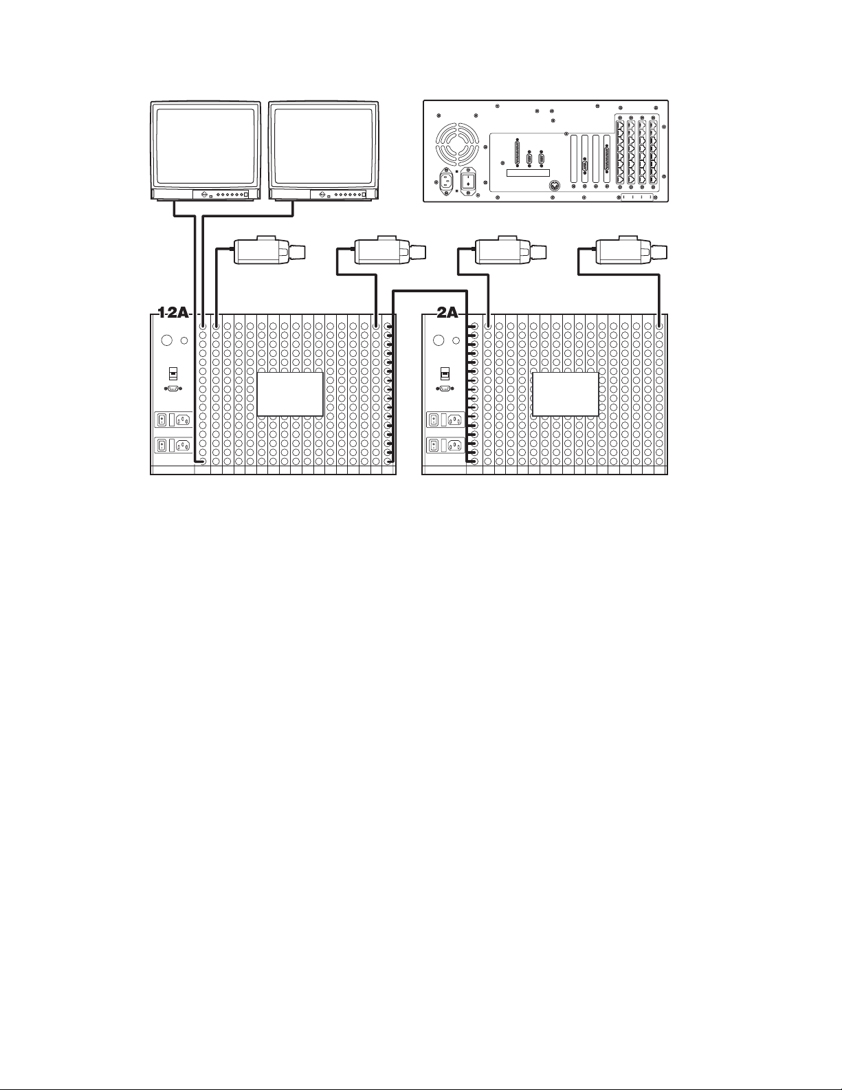
2A
2B
12A22A32A
12B22B32B
CAMS
769-976
CAMS
513-768
CAMS
257-512
VIDEO TIE LINES X16
CAMS
1-256
Figure 13. 976 X 32
Pelco Manual C1503M (11/99) 21
Page 23

Alarm Black
Out
RS-422
RS-422
Alarm Black
Out
RS-422
RS-422
961
769
753
513
Alarm Black
Out
RS-422
RS-422
Alarm Black
Out
RS-422
RS-422
Alarm Black
Out
RS-422
RS-422
497
257
Alarm Black
Out
RS-422
RS-422
Alarm Black
Out
RS-422
RS-422
241
1
Alarm Black
Out
RS-422
RS-422
CAMS
769-976
OUT
CAMS
513-768
OUT
CAMS
257-512
OUT
CAMS
1-256
OUT
REFER TO PORT
ASSIGNMENT PAGE
FOR YOUR SYSTEM
’
S
SPECIFIC DATA
CONNECTIONS
CM9760-CC1
CM9760-MXB CM9760-MXB
PRINTER COM1 COM2
35
29
28
21
20
13
12
5
16 1
CM9760-MXB
CM9760-MXB
CM9760-MXB
CM9760-MXB
32 17
CAM 1 LOOP-OUT
SYSTEM LOOPED
OUTPUTS ARE NOT
TERMINATED
CAM 16 LOOP-OUT
SUPPLIED DOWN-
FRAMING CABLES
16X RIBBON COAXIAL
CM9760-MXB
CM9760-MXB
2A
2B
12A22A32A
12B22B32B
CAMS
769-976
CAMS
513-768
CAMS
257-512
VIDEO TIE LINES X16
CAMS
1-256
Figure 14. 976 X 32 Looping
22 Pelco Manual C1503M (11/99)
Page 24

16 1
Alarm Black
Out
RS-422
RS-422
CM9760-MXB
32 17
241 1
CAMS
1-256
CM9760-CC1
SUPPLIED DOWNFRAMING CABLES
16X RIBBON COAXIAL
PRINTER COM1 COM2
35292821201312
REFER TO PORT
ASSIGNMENT PAGE
FOR YOUR SYSTEM’S
SPECIFIC DATA
CONNECTIONS
5
Alarm Black
Out
RS-422
RS-422
CM9760-MXB
48 33
2C
Alarm Black
Out
RS-422
RS-422
CM9760-MXB
SUPPLIED DOWNFRAMING CABLES
16X RIBBON COAXIAL
Figure 15. 256 X 48
Pelco Manual C1503M (11/99) 23
Page 25

16 1
Alarm Black
Out
RS-422
RS-422
CM9760-MXB
32 17
241 1
CAMS
1-256
CM9760-CC1
PRINTER COM1 COM2
35292821201312
REFER TO PORT
ASSIGNMENT PAGE
FOR YOUR SYSTEM’S
SPECIFIC DATA
CONNECTIONS
5
Alarm Black
Out
RS-422
RS-422
CM9760-MXB
48 33
2C
Alarm Black
Out
RS-422
RS-422
CAMS
1-256
OUT
SUPPLIED DOWNFRAMING CABLES
16X RIBBON COAXIAL
SUPPLIED DOWNFRAMING CABLES
16X RIBBON COAXIAL
CAM 1 LOOP-OUT
SYSTEM LOOPED
OUTPUTS ARE NOT
TERMINATED
CAM 16 LOOP-OUT
CM9760-MXB
Figure 16. 256 X 48 Looping
24 Pelco Manual C1503M (11/99)
Page 26

16 1
481 257 241 1
CM9760-CC1
PRINTER COM1 COM2
35292821201312
REFER TO PORT
ASSIGNMENT PAGE
FOR YOUR SYSTEM’S
SPECIFIC DATA
CONNECTIONS
5
Alarm Black
RS-422
RS-422
Out
CAMS
257-496
Alarm Black
RS-422
RS-422
Out
CM9760-MXB CM9760-MXB
32 17
Alarm Black
RS-422
RS-422
Out
Alarm Black
RS-422
RS-422
Out
CAMS
1-256
SUPPLIED DOWNFRAMING CABLES
16X RIBBON COAXIAL
CM9760-MXB
CM9760-MXB
48 33
SUPPLIED DOWNFRAMING CABLES
16X RIBBON COAXIAL
12C 2C
Alarm Black
Out
RS-422
RS-422
CM9760-MXB
Figure 17. 496 X 48
Pelco Manual C1503M (11/99) 25
Alarm Black
Out
RS-422
RS-422
CM9760-MXB
Page 27

16 1
481 257 241 1
CM9760-CC1
PRINTER COM1 COM2
35292821201312
REFER TO PORT
ASSIGNMENT PAGE
FOR YOUR SYSTEM’S
SPECIFIC DATA
CONNECTIONS
5
Alarm Black
RS-422
RS-422
Out
CAMS
257-496
Alarm Black
RS-422
RS-422
Out
CM9760-MXB CM9760-MXB
32 17
Alarm Black
Out
RS-422
RS-422
CM9760-MXB
Alarm Black
Out
RS-422
RS-422
CM9760-MXB
CAMS
1-256
SUPPLIED DOWNFRAMING CABLES
16X RIBBON COAXIAL
48 33
SUPPLIED DOWNFRAMING CABLES
16X RIBBON COAXIAL
12C 2C
Alarm Black
Out
RS-422
RS-422
CAMS
257-496
OUT
CM9760-MXB
Figure 18. 496 X 48 Looping
26 Pelco Manual C1503M (11/99)
Alarm Black
Out
RS-422
RS-422
CM9760-MXB
CAMS
1-256
OUT
CAM 1 LOOP-OUT
SYSTEM LOOPED
OUTPUTS ARE NOT
TERMINATED
CAM 16 LOOP-OUT
Page 28

16 1
PRINTER COM1 COM2
CM9760-CC1
VIDEO TIE LINES X16
721 513 497 257
35292821201312
REFER TO PORT
ASSIGNMENT PAGE
FOR YOUR SYSTEM’S
SPECIFIC DATA
CONNECTIONS
5
241 1
Alarm Black
RS-422
RS-422
Out
CAMS
513-736
Alarm Black
RS-422
RS-422
Out
CM9760-MXB CM9760-MXB
32 17
Alarm Black
Out
RS-422
RS-422
CM9760-MXB
Alarm Black
Out
RS-422
RS-422
CM9760-MXB
48 33
Alarm Black
RS-422
RS-422
Out
12C22C 2C
Alarm Black
Out
RS-422
RS-422
CAMS
257-512
Alarm Black
Out
RS-422
RS-422
CM9760-MXB
Alarm Black
Out
RS-422
RS-422
CM9760-MXB
Alarm Black
Out
RS-422
RS-422
CAMS
1-256
SUPPLIED DOWNFRAMING CABLES
16X RIBBON COAXIAL
SUPPLIED DOWNFRAMING CABLES
16X RIBBON COAXIAL
CM9760-MXB
CM9760-MXB
CM9760-MXB
Figure 19. 736 X 48
Pelco Manual C1503M (11/99) 27
Page 29

16 1
PRINTER COM1 COM2
CM9760-CC1
VIDEO TIE LINES X16
721 513 497 257
35292821201312
REFER TO PORT
ASSIGNMENT PAGE
FOR YOUR SYSTEM’S
SPECIFIC DATA
CONNECTIONS
5
241 1
Alarm Black
RS-422
RS-422
Out
CAMS
513-736
Alarm Black
RS-422
RS-422
Out
CM9760-MXB CM9760-MXB
32 17
Alarm Black
Out
RS-422
RS-422
CM9760-MXB
Alarm Black
Out
RS-422
RS-422
CM9760-MXB
48 33
Alarm Black
RS-422
RS-422
Out
CAMS
513-736
OUT
12C22C 2C
Alarm Black
Out
RS-422
RS-422
CAMS
257-512
CAMS
257-512
OUT
Alarm Black
Out
RS-422
RS-422
CM9760-MXB
Alarm Black
Out
RS-422
RS-422
CM9760-MXB
Alarm Black
Out
RS-422
RS-422
CAMS
1-256
CAMS
1-256
OUT
SUPPLIED DOWNFRAMING CABLES
16X RIBBON COAXIAL
SUPPLIED DOWNFRAMING CABLES
16X RIBBON COAXIAL
CAM 1 LOOP-OUT
SYSTEM LOOPED
OUTPUTS ARE NOT
TERMINATED
CAM 16 LOOP-OUT
CM9760-MXB
CM9760-MXB
CM9760-MXB
Figure 20. 736 X 48 Looping
28 Pelco Manual C1503M (11/99)
Page 30

Alarm Black
Out
RS-422
RS-422
Alarm Black
Out
RS-422
RS-422
961
769
753
513
Alarm Black
Out
RS-422
RS-422
Alarm Black
Out
RS-422
RS-422
Alarm Black
Out
RS-422
RS-422
497
257
Alarm Black
Out
RS-422
RS-422
Alarm Black
Out
RS-422
RS-422
241
1
Alarm Black
Out
RS-422
RS-422
Alarm Black
Out
RS-422
RS-422
Alarm Black
Out
RS-422
RS-422
Alarm Black
Out
RS-422
RS-422
Alarm Black
Out
RS-422
RS-422
REFER TO PORT
ASSIGNMENT PAGE
FOR YOUR SYSTEM
’
S
SPECIFIC DATA
CONNECTIONS
CM9760-CC1
CM9760-MXB CM9760-MXB
PRINTER COM1 COM2
35
29
28
21
20
13
12
5
16 1
CM9760-MXB
CM9760-MXB
CM9760-MXB
CM9760-MXB
32 17
SUPPLIED DOWN-
FRAMING CABLES
16X RIBBON COAXIAL
CM9760-MXB
CM9760-MXB
12A22A32A
12B22B32B
CM9760-MXB
CM9760-MXB CM9760-MXB
48 33
SUPPLIED DOWN-
FRAMING CABLES
16X RIBBON COAXIAL
CM9760-MXB
2B
2A
12C22C32C 2C
CAMS
769-976
CAMS
513-768
CAMS
257-512
VIDEO TIE LINES X16
CAMS
1-256
Figure 21. 976 X 48
Pelco Manual C1503M (11/99) 29
Page 31

Alarm Black
Out
RS-422
RS-422
Alarm Black
Out
RS-422
RS-422
961
769
753
513
Alarm Black
Out
RS-422
RS-422
Alarm Black
Out
RS-422
RS-422
Alarm Black
Out
RS-422
RS-422
497
257
Alarm Black
Out
RS-422
RS-422
Alarm Black
Out
RS-422
RS-422
241
1
Alarm Black
Out
RS-422
RS-422
Alarm Black
Out
RS-422
RS-422
Alarm Black
Out
RS-422
RS-422
Alarm Black
Out
RS-422
RS-422
Alarm Black
Out
RS-422
RS-422
CAMS
769-976
OUT
CAMS
513-768
OUT
CAMS
257-512
OUT
CAMS
1-256
OUT
REFER TO PORT
ASSIGNMENT PAGE
FOR YOUR SYSTEM
’
S
SPECIFIC DATA
CONNECTIONS
CM9760-CC1
CM9760-MXB CM9760-MXB
PRINTER COM1 COM2
35
29
28
21
20
13
12
5
16 1
CM9760-MXB
CM9760-MXB
CM9760-MXB
CM9760-MXB
32 17
SUPPLIED DOWN-
FRAMING CABLES
16X RIBBON COAXIAL
CM9760-MXB
CM9760-MXB
12A22A32A
12B22B32B
CM9760-MXB
CM9760-MXB CM9760-MXB
48 33
CAM 1 LOOP-OUT
SYSTEM LOOPED
OUTPUTS ARE NOT
TERMINATED
CAM 16 LOOP-OUT
SUPPLIED DOWN-
FRAMING CABLES
16X RIBBON COAXIAL
CM9760-MXB
2B
2A
12C22C32C 2C
CAMS
769-976
CAMS
513-768
CAMS
257-512
VIDEO TIE LINES X16
CAMS
1-256
Figure 22. 976 X 48 Looping
30 Pelco Manual C1503M (11/99)
Page 32

16 1
2A
Alarm Black
Out
RS-422
RS-422
CM9760-MXB
32 17
2B
Alarm Black
Out
RS-422
RS-422
241 1
CAMS
1-256
CM9760-CC1
SUPPLIED DOWNFRAMING CABLES
16X RIBBON COAXIAL
PRINTER COM1 COM2
35292821201312
REFER TO PORT
ASSIGNMENT PAGE
FOR YOUR SYSTEM’S
SPECIFIC DATA
CONNECTIONS
5
CM9760-MXB
48 33
2C
Alarm Black
Out
RS-422
RS-422
CM9760-MXB
64 49
2D
Alarm Black
Out
RS-422
RS-422
SUPPLIED DOWNFRAMING CABLES
16X RIBBON COAXIAL
SUPPLIED DOWNFRAMING CABLES
16X RIBBON COAXIAL
CM9760-MXB
Figure 23. 256 X 64
Pelco Manual C1503M (11/99) 31
Page 33

16 1
2A
Alarm Black
Out
RS-422
RS-422
CM9760-MXB
32 17
2B
Alarm Black
Out
RS-422
RS-422
241 1
CAMS
1-256
CM9760-CC1
SUPPLIED DOWNFRAMING CABLES
16X RIBBON COAXIAL
PRINTER COM1 COM2
35292821201312
REFER TO PORT
ASSIGNMENT PAGE
FOR YOUR SYSTEM’S
SPECIFIC DATA
CONNECTIONS
5
CM9760-MXB
48 33
2C
Alarm Black
Out
RS-422
RS-422
CM9760-MXB
64 49
2D
Alarm Black
Out
RS-422
RS-422
CM9760-MXB
SUPPLIED DOWNFRAMING CABLES
16X RIBBON COAXIAL
SUPPLIED DOWNFRAMING CABLES
16X RIBBON COAXIAL
CAM 1 LOOP-OUT
CAMS
1-256
OUT
SYSTEM LOOPED
OUTPUTS ARE NOT
TERMINATED
CAM 16 LOOP-OUT
Figure 24. 256 X 64 Looping
32 Pelco Manual C1503M (11/99)
Page 34

16 1
CM9760-CC1
481 257 241 1
PRINTER COM1 COM2
35292821201312
REFER TO PORT
ASSIGNMENT PAGE
FOR YOUR SYSTEM’S
SPECIFIC DATA
CONNECTIONS
5
Alarm Black
RS-422
RS-422
Out
CAMS
257-496
Alarm Black
RS-422
RS-422
Out
CM9760-MXB CM9760-MXB
32 17
Alarm Black
Out
RS-422
RS-422
CM9760-MXB
Alarm Black
Out
RS-422
RS-422
CM9760-MXB
48 33
12C
Alarm Black
RS-422
RS-422
Out
2C
Alarm Black
Out
RS-422
RS-422
CAMS
1-256
SUPPLIED DOWNFRAMING CABLES
16X RIBBON COAXIAL
SUPPLIED DOWNFRAMING CABLES
16X RIBBON COAXIAL
CM9760-MXB
CM9760-MXB
64 49
SUPPLIED DOWNFRAMING CABLES
16X RIBBON COAXIAL
12D 2D
Alarm Black
Out
RS-422
RS-422
CM9760-MXB
Alarm Black
Out
RS-422
RS-422
CM9760-MXB
Figure 25. 496 X 64
Pelco Manual C1503M (11/99) 33
Page 35

16 1
CM9760-CC1
481 257 241 1
PRINTER COM1 COM2
35292821201312
REFER TO PORT
ASSIGNMENT PAGE
FOR YOUR SYSTEM’S
SPECIFIC DATA
CONNECTIONS
5
Alarm Black
RS-422
RS-422
Out
CAMS
257-496
Alarm Black
RS-422
RS-422
Out
CM9760-MXB CM9760-MXB
32 17
Alarm Black
Out
RS-422
RS-422
CM9760-MXB
Alarm Black
Out
RS-422
RS-422
CM9760-MXB
48 33
12C
Alarm Black
RS-422
RS-422
Out
2C
Alarm Black
Out
RS-422
RS-422
CAMS
1-256
SUPPLIED DOWNFRAMING CABLES
16X RIBBON COAXIAL
SUPPLIED DOWNFRAMING CABLES
16X RIBBON COAXIAL
CM9760-MXB
CM9760-MXB
64 49
SUPPLIED DOWNFRAMING CABLES
16X RIBBON COAXIAL
12D 2D
Alarm Black
RS-422
RS-422
Out
CAMS
257-496
OUT
Alarm Black
Out
RS-422
RS-422
CAMS
1-256
OUT
CAM 1 LOOP-OUT
SYSTEM LOOPED
OUTPUTS ARE NOT
TERMINATED
CAM 16 LOOP-OUT
CM9760-MXB
CM9760-MXB
Figure 26. 496 X 64 Looping
34 Pelco Manual C1503M (11/99)
Page 36

16 1
PRINTER COM1 COM2
CM9760-CC1
VIDEO TIE LINES X16
721 513 497 257
35292821201312
REFER TO PORT
ASSIGNMENT PAGE
FOR YOUR SYSTEM’S
SPECIFIC DATA
CONNECTIONS
5
241 1
Alarm Black
RS-422
RS-422
Out
CAMS
513-736
Alarm Black
RS-422
RS-422
Out
CM9760-MXB CM9760-MXB
32 17
Alarm Black
Out
RS-422
RS-422
CM9760-MXB
Alarm Black
Out
RS-422
RS-422
CM9760-MXB
48 33
Alarm Black
RS-422
RS-422
Out
12C22C
Alarm Black
Out
RS-422
RS-422
CAMS
257-512
Alarm Black
Out
RS-422
RS-422
CM9760-MXB
Alarm Black
Out
RS-422
RS-422
CM9760-MXB
2C
Alarm Black
Out
RS-422
RS-422
CAMS
1-256
SUPPLIED DOWNFRAMING CABLES
16X RIBBON COAXIAL
SUPPLIED DOWNFRAMING CABLES
16X RIBBON COAXIAL
CM9760-MXB
CM9760-MXB
CM9760-MXB
64 49
SUPPLIED DOWNFRAMING CABLES
16X RIBBON COAXIAL
Alarm Black
Out
RS-422
RS-422
CM9760-MXB
12D22D
Alarm Black
Out
RS-422
RS-422
CM9760-MXB
2D
Alarm Black
Out
RS-422
RS-422
CM9760-MXB
Figure 27. 736 X 64
Pelco Manual C1503M (11/99) 35
Page 37

16 1
PRINTER COM1 COM2
CM9760-CC1
VIDEO TIE LINES X16
721 513 497 257
35292821201312
REFER TO PORT
ASSIGNMENT PAGE
FOR YOUR SYSTEM’S
SPECIFIC DATA
CONNECTIONS
5
241 1
Alarm Black
RS-422
RS-422
Out
CAMS
513-736
Alarm Black
Out
RS-422
RS-422
CM9760-MXB CM9760-MXB
32 17
Alarm Black
Out
RS-422
RS-422
CM9760-MXB
Alarm Black
Out
RS-422
RS-422
CM9760-MXB
48 33
Alarm Black
RS-422
RS-422
Out
12C22C
Alarm Black
Out
RS-422
RS-422
CAMS
257-512
Alarm Black
Out
RS-422
RS-422
CM9760-MXB
Alarm Black
Out
RS-422
RS-422
CM9760-MXB
2C
Alarm Black
Out
RS-422
RS-422
CAMS
1-256
SUPPLIED DOWNFRAMING CABLES
16X RIBBON COAXIAL
SUPPLIED DOWNFRAMING CABLES
16X RIBBON COAXIAL
CM9760-MXB
CM9760-MXB
CM9760-MXB
64 49
SUPPLIED DOWNFRAMING CABLES
16X RIBBON COAXIAL
Alarm Black
RS-422
RS-422
12D22D
Out
CAMS
513-736
OUT
Alarm Black
RS-422
RS-422
Out
CAMS
257-512
OUT
2D
Alarm Black
Out
RS-422
RS-422
CAMS
1-256
OUT
CAM 1 LOOP-OUT
SYSTEM LOOPED
OUTPUTS ARE NOT
TERMINATED
CAM 16 LOOP-OUT
CM9760-MXB
CM9760-MXB
CM9760-MXB
Figure 28. 736 X 64 Looping
36 Pelco Manual C1503M (11/99)
Page 38

16 1
PRINTER COM1 COM2
CM9760-CC1
VIDEO TIE LINES X16
961 769 753 513
35292821201312
REFER TO PORT
ASSIGNMENT PAGE
FOR YOUR SYSTEM’S
SPECIFIC DATA
CONNECTIONS
5
497 257
241 1
Alarm Black
Out
RS-422
RS-422
CAMS
769-976
Alarm Black
Out
RS-422
RS-422
CM9760-MXB CM9760-MXB
32 17
Alarm Black
RS-422
RS-422
CM9760-MXB
Out
Alarm Black
RS-422
RS-422
CM9760-MXB
Out
48 33
Alarm Black
Out
RS-422
RS-422
Alarm Black
Out
RS-422
RS-422
CAMS
513-768
12A22A32A
Alarm Black
Out
RS-422
RS-422
CAMS
257-512
CM9760-MXB
12B22B32B
Alarm Black
Out
RS-422
RS-422
CM9760-MXB
12C22C32C 2C
Alarm Black
Out
RS-422
RS-422
2A
CM9760-MXB
2B
CM9760-MXB
Alarm Black
Alarm Black
Alarm Black
Out
RS-422
RS-422
Out
RS-422
RS-422
Out
RS-422
RS-422
CAMS
1-256
SUPPLIED DOWNFRAMING CABLES
16X RIBBON COAXIAL
SUPPLIED DOWNFRAMING CABLES
16X RIBBON COAXIAL
CM9760-MXB
CM9760-MXB CM9760-MXB
CM9760-MXB
64 49
SUPPLIED DOWNFRAMING CABLES
16X RIBBON COAXIAL
Alarm Black
RS-422
RS-422
CM9760-MXB
Out
Alarm Black
Out
RS-422
RS-422
CM9760-MXB CM9760-MXB
12D22D32D 2D
Alarm Black
Out
RS-422
RS-422
Alarm Black
CM9760-MXB
Out
RS-422
RS-422
Figure 29. 976 X 64
Pelco Manual C1503M (11/99) 37
Page 39

16 1
PRINTER COM1 COM2
CM9760-CC1
VIDEO TIE LINES X16
961 769 753 513
35292821201312
REFER TO PORT
ASSIGNMENT PAGE
FOR YOUR SYSTEM’S
SPECIFIC DATA
CONNECTIONS
5
497 257
241 1
Alarm Black
Out
RS-422
RS-422
CAMS
769-976
Alarm Black
Out
RS-422
RS-422
CM9760-MXB CM9760-MXB
32 17
Alarm Black
Out
RS-422
RS-422
CM9760-MXB
Alarm Black
RS-422
RS-422
CM9760-MXB
Out
48 33
Alarm Black
Out
RS-422
RS-422
Alarm Black
Out
RS-422
RS-422
CAMS
513-768
12A22A32A
Alarm Black
Out
RS-422
RS-422
CM9760-MXB
12B22B32B
Alarm Black
Out
RS-422
RS-422
CM9760-MXB
12C22C32C 2C
Alarm Black
Out
RS-422
RS-422
CAMS
257-512
CM9760-MXB
CM9760-MXB
2A
Alarm Black
2B
Alarm Black
Alarm Black
Out
RS-422
RS-422
Out
RS-422
RS-422
Out
RS-422
RS-422
CAMS
1-256
SUPPLIED DOWNFRAMING CABLES
16X RIBBON COAXIAL
SUPPLIED DOWNFRAMING CABLES
16X RIBBON COAXIAL
CM9760-MXB
CM9760-MXB CM9760-MXB
CM9760-MXB
64 49
SUPPLIED DOWNFRAMING CABLES
16X RIBBON COAXIAL
Alarm Black
Out
RS-422
RS-422
CAMS
769-976
OUT
Alarm Black
Out
RS-422
RS-422
CAMS
513-768
OUT
12D22D32D 2D
Alarm Black
Out
RS-422
RS-422
CAMS
257-512
OUT
Alarm Black
Out
RS-422
RS-422
CAMS
1-256
OUT
CAM 1 LOOP-OUT
SYSTEM LOOPED
OUTPUTS ARE NOT
TERMINATED
CAM 16 LOOP-OUT
CM9760-MXB
CM9760-MXB CM9760-MXB
CM9760-MXB
Figure 30. 976 X 64 Looping
38 Pelco Manual C1503M (11/99)
Page 40

NOTES
Pelco Manual C1503M (11/99) 39
Page 41

WARRANTY AND RETURN INFORMATION
WARRANTY
Pelco will repair or replace, without charge, any merchandise proved defective in material or workmanship for a period of one year after the date of
shipment. Exceptions to this warranty are as noted below:
• Three years on Genex™ Series (multiplexers, server, and keyboard).
• Two years on all standard motorized and fixed focal length lenses.
• Two years on Esprit™, Legacy®, Intercept®, PV1000 Series, CM6700/
CM8500/CM9500/CM9750/CM9760 Matrix, Spectra®, DF5 Series and DF8
Fixed Dome products.
• Two years on WW5700 series window wiper (excluding wiper blades).
• Two years on cameras.
• Six months on all pan and tilts, scanners or preset lenses used in continuous
motion applications (that is, preset scan, tour and auto scan modes).
Pelco will warrant all replacement parts and repairs for 90 days from the date
of Pelco shipment. All goods requiring warranty repair shall be sent freight
prepaid to Pelco, Clovis, California. Repairs made necessary by reason of
misuse, alteration, normal wear, or accident are not covered under this warranty.
Pelco assumes no risk and shall be subject to no liability for damages or loss
resulting from the specific use or application made of the Products. Pelco’s
liability for any claim, whether based on breach of contract, negligence, infringement of any rights of any party or product liability, relating to the Products shall not exceed the price paid by the Dealer to Pelco for such Products.
In no event will Pelco be liable for any special, incidental or consequential
damages (including loss of use, loss of profit and claims of third parties) however caused, whether by the negligence of Pelco or otherwise.
The above warranty provides the Dealer with specific legal rights. The Dealer may
also have additional rights, which are subject to variation from state to state.
REVISION HISTORY
Manual # Date Comments
C1503M 11/99 Original version.
If a warranty repair is required, the Dealer must contact Pelco at (800) 2899100 or (559) 292-1981 to obtain a Repair Authorization number (RA), and
provide the following information:
1. Model and serial number
2. Date of shipment, P.O. number, Sales Order number, or Pelco invoice number
3. Details of the defect or problem
If there is a dispute regarding the warranty of a product which does not fall
under the warranty conditions stated above, please include a written explanation with the product when returned.
Ship freight prepaid to: Pelco
Method of return shipment shall be the same or equal to the method by which
the item was received by Pelco.
RETURNS
In order to expedite parts returned to the factory for repair or credit, please
call the factory at (800) 289-9100 or (559) 292-1981 to obtain an authorization number (CA number if returned for credit, and RA number if returned for
repair). Goods returned for repair or credit should be clearly identified with
the assigned CA/RA number and freight should be prepaid. All merchandise
returned for credit may be subject to a 20% restocking and refurbishing charge.
Ship freight prepaid to: Pelco
300 West Pontiac Way
Clovis, CA 93612-5699
300 West Pontiac Way
Clovis, CA 93612-5699
® Pelco, the Pelco logo, and System 9760 are registered trademarks of Pelco. © Copyright 1999, Pelco. All rights reserved.
40 Pelco Manual C1503M (11/99)
 Loading...