

Page 1
INSTALLATION
C11-UM, CM1751, and TB1751 Mounts
Wall, Ceiling, Pedestal, T-Bar, Gang
Box Mounts for Cameras
C2301M (4/18)
Page 2

Important Safety Instructions
1. Installation and servicing should only be done by qualified service personnel and conform to all local codes.
2. Use only installation methods and materials capable of supporting four times the maximum specified load.
3. Use stainless steel hardware to fasten the mount to outdoor surfaces.
4. To prevent damage from water leakage when installing a mount outdoors on a roof or wall, apply sealant around the bolt holes between the
mount and mounting surface.
Description
The CM1751, TB1751, and C11-UM camera mounts are universal mount kits for installing most box type cameras with 1/4 x 20-inch mounting
holes weighing up to 7 pounds (3.18 kg). All mount kits have a swivel head for 360 degree pan adjustment and 90 degree tilt adjustment of the
camera. These mounts are not recommended for use with enclosures.
The CM1751 is designed for mounting a camera to a wall, ceiling, or pedestal. The TB1751 has a T-bar mount and is used for installing a camera
to a false ceiling. C11-UM can be mounted directly to a single gang box or wall. The mounts can be configured to two different lengths with the
extension tube included in the kits.
This manual contains the installation instructions for the following mounts:
CM1751 Mount
Qty Description
1 Mounting Base
1 Extension tube, 3 in (8 cm)
1 Extension tube, 7 in (18 cm)
1 Ball socket assembly (includes ball stud, anvil, sleeve, mounting nut, and locking arm)
1 Tube of Thread Adhesive
TB1751 Mount
Qty Description
1T-Bar Clip
1 Extension tube, 1 in (2.6 cm)
1 Extension tube, 2.75 in (7 cm)
1 Ball socket assembly (includes ball stud, anvil, sleeve, mounting nut, and locking arm)
1 Tube of Thread Adhesive
C11-UM Mount
Qty Description
1 Mounting Plate
1 Extension tube, 1 in (2.6 cm)
1 Extension tube, 2.75 in (7 cm)
1 Ball socket assembly (includes ball stud, anvil, sleeve, mounting nut, and locking arm)
1 Tube of Thread Adhesive
2 C2301M (3/18)
Page 3
Installation
CM1751 MOUNT
1. Apply a drop of thread adhesive to the threads of both sides of the Extension Tube that will be used. Discard the unused Extension Tube.
2. Screw the Extension Tube to the Ball Socket Assembly until hand tight. Screw on the mounting base to the other end of the Extension Tube
until hand tight.
Figure 1. Attach the Extension Tube
Figure 2. Screw on the Mounting Base
3. Place the Mounting Base against the mounting surface and draw marks for drilling a minimum of two mounting holes.
4. Drill the holes and fasten the mount to the surface with 1/4-20 hardware (not supplied).
Figure 3. Attach the CM1751 Mount
C2301M (3/18) 3
Page 4

TB1751 MOUNT
1. Squeeze the T-rail clip onto the T-bar.
2. Apply a drop of thread adhesive to the external threads of the Extension Tube that will be used. Discard the unused Extension Tube.
3. Screw the Extension Tube to the Ball Socket Assembly until hand tight.
Figure 4. Attach the TB1751 Mount to the T-bar
Figure 5. Attach the Ball Socket Assembly to the Extension Tube
4. Attach the ball socket/extension tube assembly to the threaded stud on the T-rail clip.
Figure 6. Attach to the Threaded Stud
4 C2301M (3/18)
Page 5

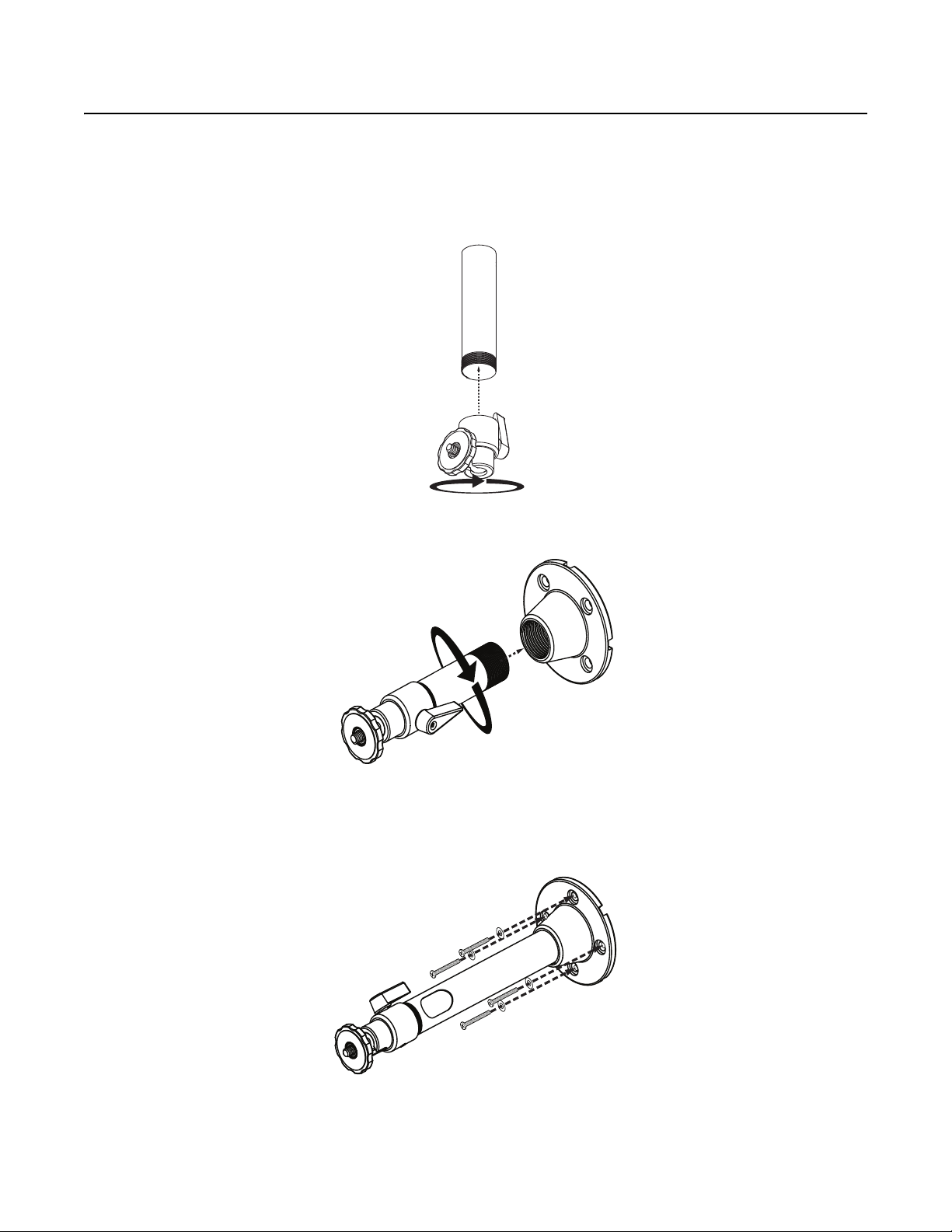
C11-UM MOUNT
1. Pull the wire and cable for the camera through the mounting plate and then attach the mounting plate to the mounting surface (hardware
not supplied).
2. Apply a drop of thread adhesive to the external threads of the Extension Tube that will be used. Discard the unused Extension Tube.
3. Screw the Extension Tube to the Ball Socket Assembly until hand tight.
Figure 7. Attach the C11-UM Mount to the Mounting Surface
Figure 8. Attach the Head of the C11-UM Mount
Figure 9. Rotate the Head of the C11-UM Mount
C2301M (3/18) 5
Page 6

4. Attach the ball socket/extension tube assembly to the threaded stud on the mounting plate.
CAMERA
1. Attach the camera to the 1/4-20 threaded stud on the swivel head and tighten the nuts against the camera.
2. Loosen the locking arm on the swivel assembly, if necessary. Position the camera in the desired position and tighten the locking arm.
3. Connect the wires and cable to the back of the camera (Refer to the manual supplied with the camera for instructions.).
Figure 10. Attach to the Threaded Stud on the Mounting Plate
6 C2301M (3/18)
Page 7

WARRANTY STATEMENT
For information about Pelco’s product warranty and thereto related information, refer to www.pelco.com/warranty.
REVISION HISTORY
Manual # Date Comments
C2301M 4/2018 Original version.
Pelco, the Pelco logo, and other trademarks associa ted with Pelco products referred to in this publication are trademarks of Pelco, Inc. or its affilia tes. © Copyright 2018, Pelco, Inc.
ONVIF and the ONVIF logo are trademarks of ONVIF Inc. All other product names and services are the property of their respective companies. All rights reserved.
Product specifications and availability are subject to change without notice.
The absence of a trademark or registered trademark from this document does not constitute a waiver of intellectual property rights.
Page 8

www.pelco.com
Pelco, Inc. Worldwide Headquarters 625 W. Alluvial Fresno, California 93711 USA
USA & Canada Tel (800) 289-9100 Fax (800) 289-9150
International Tel +1 (559) 292-1981 Fax +1 (559) 348-1120
 Loading...