

Page 1

®
ICI3000P
Inter-Check Point-Of-Sale
Monitoring System
Installation/Operation Manual
C1043M-A (2/96)
PELCO • 3500 Pelco Way, Clovis, CA 93612-5699 • USA • (800) 289-9100 or (1-559) 292-1981
FAX (800) 289-9150 or (1-559) 292-3827
Page 2

TABLE OF CONTENTS
Section Page
1.0 WARNINGS.......................................................................................................................................1
2.0 SCOPE..............................................................................................................................................2
2.1 DESCRIPTION ........................................................................................................................ 2
3.0 INSTALLATION..................................................................................................................................3
3.1 SETTING UP ICI1000PIM PARAMETERS AND BENCH TESTING .......................................3
3.2 ICI3000WK INSTALLATION.....................................................................................................4
3.3 ICI3008/ICI3016 INSTALLATION.............................................................................................5
3.3.1 ALARM PIN-OUT CONFIGURATION.........................................................................7
3.4 EXTERNAL VIDEO ADJUSTMENTS ......................................................................................8
4.0 PROGRAMMING...............................................................................................................................9
4.1 REGISTER 1 OR 2 SELECT...................................................................................................9
4.1.1 REGISTER SELECTION USING THE HOT KEY F1..................................................9
4.2 OPERATOR # 1 OR 2..............................................................................................................9
4.2.1 OPERATOR SELECTION USING THE HOT KEY F2 ..............................................10
4.3 EXCEPTIONS ON/OFF .........................................................................................................10
4.3.1 EXCEPTIONS ON/OFF USING THE HOT KEY F3..................................................10
4.4 CAMERA SELECT ................................................................................................................10
4.4.1 CAMERA SELECT USING HOT KEY F9 ....................................................................10
4.5 SCREEN PRINT ON/OFF .....................................................................................................10
4.5.1 SCREEN PRINT ON/OFF USING HOT KEY F4 ......................................................10
4.6 AUTO CAMERA SEARCH ON/OFF ......................................................................................11
4.6.1 AUTO CAMERA SEARCH ON/OFF USING HOT KEY F12.....................................11
4.7 REVERSE VIDEO ON/OFF ...................................................................................................11
4.7.1 REVERSE VIDEO ON/OFF USING HOT KEY F10..................................................11
4.8 SYSTEM PROGRAM ............................................................................................................11
4.8.1 NUMBER OF CHARACTERS PER LINE .................................................................11
4.8.2 NUMBER OF LINES FOR SMALL SCREENS 1 AND 2 ..........................................12
4.8.3 SMALL SCREEN POSITION 1 OR 2 .......................................................................12
4.8.4 LARGE SCREEN POSITION 1 OR 2 .......................................................................12
4.8.5 ALARM DWELL TIME...............................................................................................12
4.8.6 CHANNEL PROGRAM MENU .................................................................................13
4.8.7 PRINTER PARAMETERS ........................................................................................14
4.8.8 SET CLOCK .............................................................................................................14
4.8.9 EXTERNAL CAMERA SELECT ...............................................................................14
4.8.10 SHADOW LIST PROGRAMMING ............................................................................15
4.9 EXCEPTIONS........................................................................................................................16
4.9.1 EXCEPTIONS USING THE COLUMN SPECIFIC STRATEGY ................................17
4.9.2 EXCEPTIONS USING THE GLOBAL EXCEPTION STRATEGY .............................17
4.9.3 EXCEPTIONS USING THE PRICE POINT EDITING STRATEGY...........................18
4.9.4 EXCEPTIONS WITH DESCRIPT ORS......................................................................19
5.0 SUMMARY OF EXCEPTION KEYBO ARD DEFINITIONS:.............................................................19
5.1 REGISTER MASKING...........................................................................................................20
5.2 SYS SAVE/SYS READ ..........................................................................................................20
Inter-Check® is a registered trademark of Pelco.
®PELCO and the Pelco logo are registered trademarks of Pelco.
©Copyright 1996, Pelco. All rights reserved.
ii Pelco Manual C1043M-A (2/96)
Page 3

6.0 HOT KEY SUMMARY LIST .............................................................................................................21
7.0 TROUBLESHOOTING ....................................................................................................................23
8.0 POWER-UP PROCEDURE FOR THE ICI3000P ............................................................................24
9.0 SPECIFICATIONS...........................................................................................................................25
9.1 OUTPUT DEFINITIONS ........................................................................................................ 26
9.2 DB9 PINOUT ......................................................................................................................... 26
10.0 WARRANTY AND RETURN INFORMATION..................................................................................27
LIST OF ILLUSTRATIONS
Figure Page
1 TYPICAL ICI3000P SYSTEM USED WITH STAND-ALONE CAMERAS ..............................................2
2 ICI3000P PARTYLINE WIRING CONFIGURATION..............................................................................4
3 DEFAULTING INTER-CHECK SYSTEM. ..............................................................................................5
4 CASCADING THE ICI30008 OR ICI3016..............................................................................................6
5 ALARM PIN-OUT CONFIGURATIONS .................................................................................................7
6 VIDEO ADJUSTMENT LOCATIONS.....................................................................................................8
7 INTER-CHECK'S TW O TEXT SCREENS .............................................................................................9
8 DB25 PRINTER CONNECTOR TO DB9 ICI3000P UNIT PIN ASSIGNMENTS.................................14
REVISION HISTORY
Manual # Date Comments
C1043M-A 2/96 Revised to incorporate new installation/operation information throughout.
Pelco Manual C1043M-A (2/96) iii
Page 4

(This page intentionally left blank.)
iv Pelco Manual C1043M-A (2/96)
Page 5
INSTALLATION/OPERATION MANUAL
ICI3000P INTER-CHECK® POINT-OFSALE MONITORING SYSTEM
1.0 WARNINGS
Prior to installation and use of this product, the following
WARNINGS should be observed.
1.Installation and servicing should only be done by
qualified service personnel and conform to all
Local codes.
2. Unless the unit is specifically marked as a NEMA
Type 3-6P enclosure, it is designed for indoor use
only and it must not be installed where exposed to
rain and moisture.
3. The product may bear the following marks:
This symbol indicates that dangerous voltage
constituting a risk of electric shock is present
within this unit.
CAUTION:
TO REDUCE THE RISK OF ELECTRICAL
SHOCK, DO NOT REMOVE COVER. NO
USER-SERVICEABLE PARTS INSIDE.
REFER SERVICING TO QUALIFIED
SERVICE PERSONNEL.
4. Only use replacement parts recommended by
PELCO.
5.After replacement/repair of this unit’s electrical
components, conduct a resistance measurement
between line and exposed parts to verify the exposed
parts have not been connected to line circuitry.
This symbol indicates that there are important
operating and maintenance instructions in the
literature accompanying this unit.
CAUTION:
RISK OF ELECTRIC SHOCK.
DO NOT OPEN.
Please thoroughly familiarize yourself with the information in this manual
prior to installation and operation.
Pelco Manual C1043M-A (2/96) 1
Page 6
2.0 SCOPE
2.1 DESCRIPTION
The information contained within this manual covers
the installation and operation of the Inter-Check
ICI3000P cash register interface system. Installation
should be in accordance with all applicable local and
national electric codes, using approved materials only.
Please familiarize yourself with the information within
this manual prior to installation and operation.
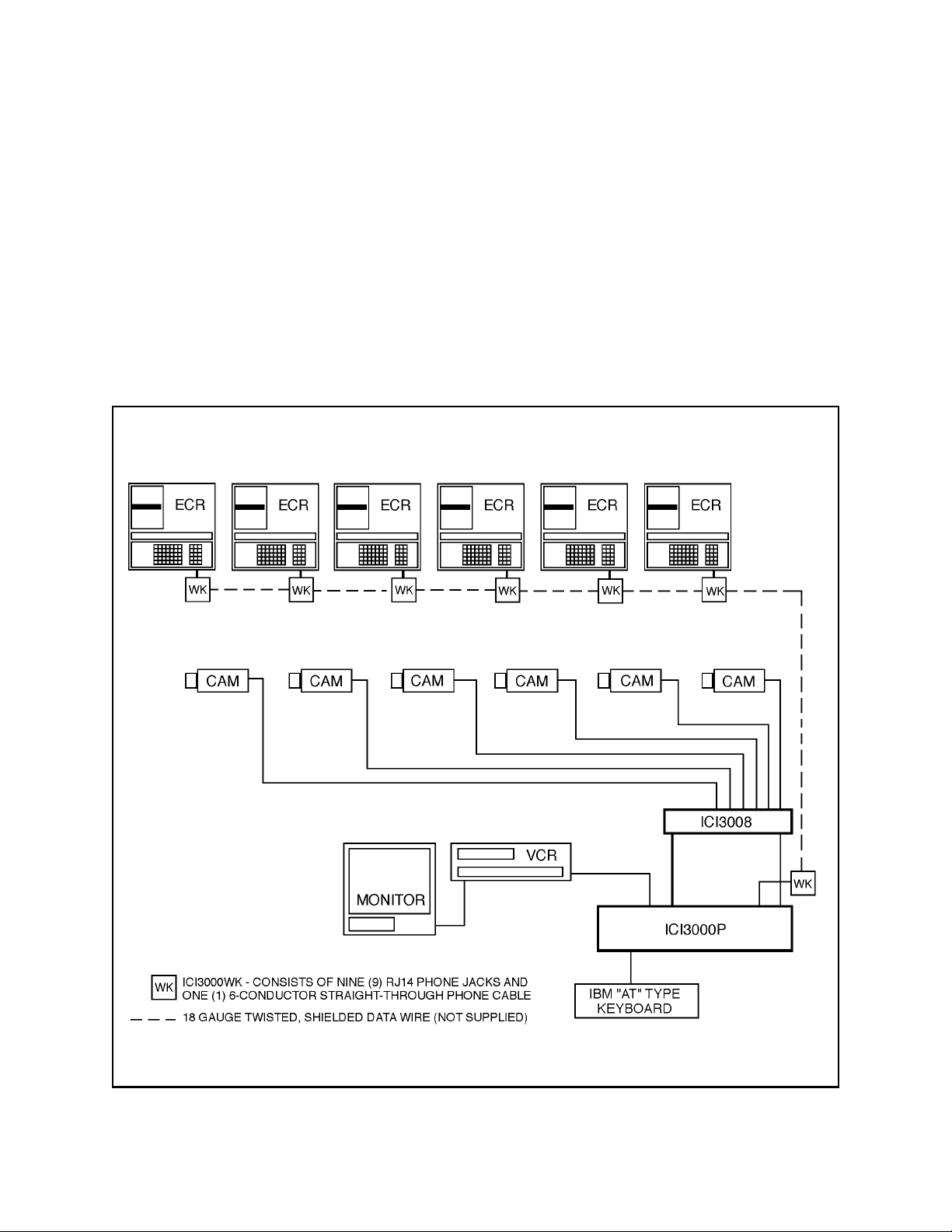
These units are point-of-sale (POS) monitoring devices
capable of monitoring up to sixteen (16) POS terminals simultaneously with up to thirty-two (32) units installed at one time. Standard features include: fifteen
programmable exceptions, two video inputs, one video
output and two alarm outputs. Increased video inputs
and alarm outputs may be obtained by interfacing with
an optional Inter-Check switcher.
Figure 1. Typical ICI3000P System with Fixed Cameras
2 Pelco Manual C1043M-A (2/96)
Page 7

3.0 INSTALLATION
3.1 SETTING UP ICI1000PIM
PARAMETERS AND BENCH
TESTING
NOTE: Please familiarize yourself with the
information in this manual prior to installation
and operation. Contact the customer's register
dealer/installer prior to installation and operation. Some warranties and/or service agreements may be affected.
1. Set the ICI1000PIM switch settings for your register according to the PIM manual (C1005M).
Make sure that switch number 2 on switch bank 1
is placed in the [-] "UP" or “POLLING” position.
Also, you must address each PIM individually;
refer to page #2 in your ICI1000PIM manual.
2. Plug the data (phone-style) cable supplied with the
ICI3000WK between the ICI1000PIM set to address #1 and the port labeled DATA IN on the
ICI3000P unit.
3. Connect a coaxial cable between the port labeled
“VIDEO OUT” of the ICI3000P and a CCTV
monitor.
4. Press the [1] one key on your keyboard while powering up the ICI3000P. The following will be displayed on your screen:
!!DEF AULTS LOADED!!
ICI3000P BY PELCO, INC . VER. X.X
CRC = YYYY
CALCULATED CRC = ZZZZ
5. Power up the ICI1000PIM with the supplied transformer.
7. To verify communication between your
ICI1000PIM and the ICI3000P, press [I] on the
keyboard and the following will be displayed:
Poll initialized!
Reg. polled = 1 1 Reg. answer!
Reg. polled = 2 2 No reg. answer!
Reg. polled = 3 3 No reg. answer! etc.
The display will poll for 32 ICI1000PIM addresses, and
then repeat display the addresses that answer.
8. Stop polling by pressing [P] again. The following
message will be displayed:
Poll watch off!
9. Select the Register PIM by pressing [F1] then [1]
followed by [Reg #] and [ENT].
10. Power down the ICI1000PIM. Power ICI1000PIM
up again.
11. A prompt will appear on the bottom of the screen.
Verify that this prompt matches the description set
forth in the manual supplied with your interface
cable.
12. Repeat these steps for the remainder of your
ICI1000PIM’s
NOTE: Each ICI1000PIM must have a different Polling address. Refer to the ICI1000PIM
manual for proper settings.
13. After polling each ICI1000PIM, power down the
ICI3000P and begin installation of the ICI1000PIM
and cash register interface cable into each cash register. Refer to the manual supplied with your inter face cable for proper installation.
6. Press [P] on the keyboard and the following will
be displayed:
Poll watch on!
Pelco Manual C1043M-A (2/96) 3
Page 8
DIP SWITCH DESCRI PT I ON--
Swit c h # Funct i on
1
2
3
4
Bank addr ess
Bank addr ess
Bank addr ess
Bank addr ess
5
6
7
8
l oop
baud rat e
NC
NC
12
345678
OPEN
12345678910111216 15 14 13VIDEO O UT
VIDEO INP UTS
TO MONI
CAMERAS 1- 15
12345678910111216 15 14 13VIDEO O UT
VIDEO INP UTS
CAMERAS 16- 31
Addr ess =
Addr ess = 0001
0000
Loop = 1
Loop =
Cove r mus t b e re moved t o access t his DIPSwitch
*
select
select
0
TOR ORVCR
3.2 ICI3000WK INSTALLATION
DIP SWITCH DESCRI PT I ON--
Swit c h # Funct i on
1
2
3
4
Bank addr ess
Bank addr ess
Bank addr ess
Bank addr ess
5
6
7
8
l oop
baud rat e
NC
NC
12
345678
OPEN
12345678910111216 15 14 13VIDEO O UT
VIDEO INP UTS
TO MONI
CAMERAS 1- 15
12345678910111216 15 14 13VIDEO O UT
VIDEO INP UTS
CAMERAS 16- 31
Addr ess =
Addr ess = 0001
0000
Loop = 1
Loop =
Cove r mus t b e re moved t o access t his DIPSwitch
*
select
select
0
TOR ORVCR
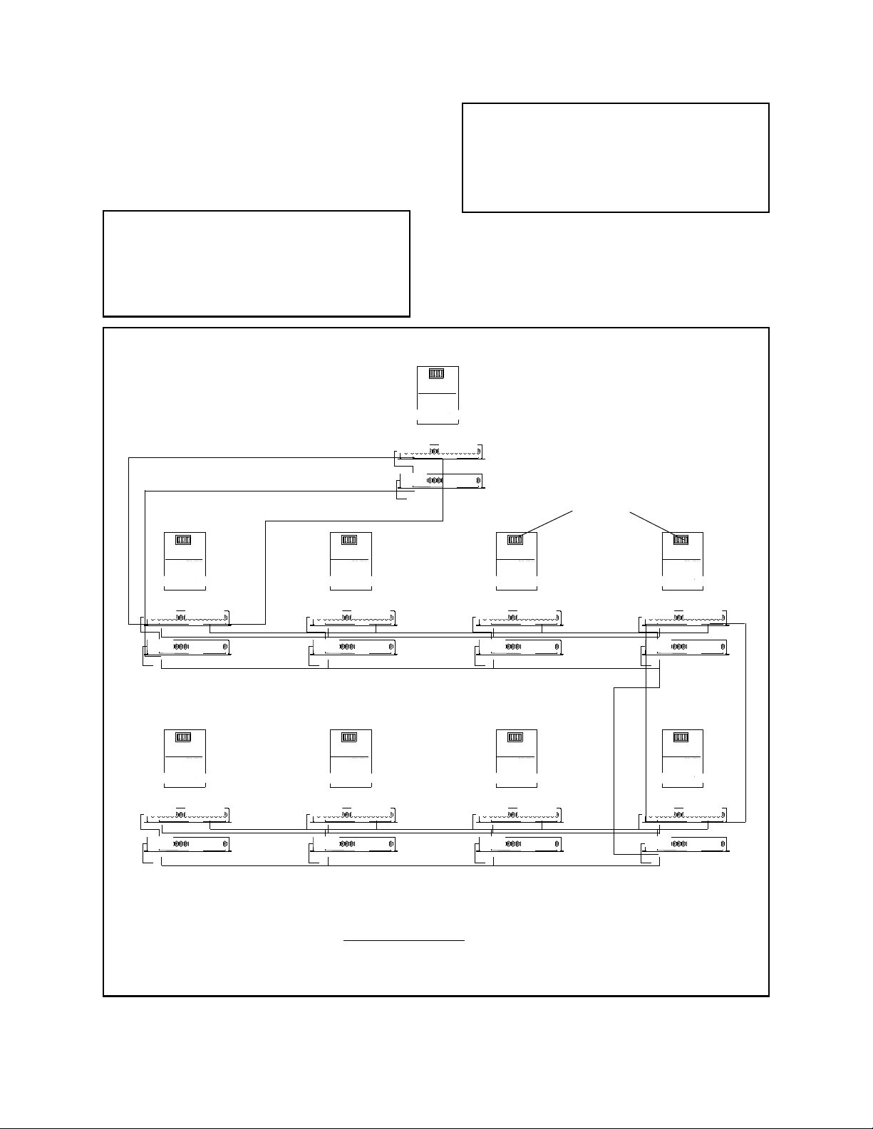
1. Install an 18 AWG, 3-conductor shielded cable between each RJ14 phone jack at each cash register .
Refer to Figure 2 for appropriate wiring configuration.
NOTE: Do not power up the ICI3000P unit
until all other connections have been made. Use
only the transformer supplied with your
ICI3000P unit. Other power supplies may cause
damage to the unit.
12
345678
OPEN
DIP SWITCH DESCRI PT I ON--
Swit c h # Funct i on
1
Bank addr ess
Bank Address
2
Bank addr ess
Bank Address
3
Bank addr ess
Bank Address
4
Bank addr ess
Bank Address
5
Loop Select
select
l oop
6
Baud Rate Select
baud rat e
select
7
WHT BLUE
NC
NC
8
NC
NC
NOTE: Cover must be removed to access this dip switch.
Cove r mus t b eremoved t o access t his DIPSwitch
*
BLK
RED GRN
TO MONI
Loop =
CAMERAS 16- 31
Addr ess = 0001
YEL
VIDEO INP UTS
Loop = 1
CAMERAS 1- 15
Addr ess =
VIDEO INP UTS
TOR ORVCR
Shadow switchers are available in either 8 or 16 positions.
0
12345678910111216 15 14 13VIDEO O UT
0000
12345678910111216 15 14 13VIDEO O UT
12
345678
OPEN
DIP SWITCH DESCRIPTI ON--
Swit c h # Funct i on
1
Bank addr ess
Bank Address
2
Bank addr ess
Bank Address
3
Bank addr ess
Bank Address
4
Bank addr ess
Bank Address
5
Loop Select
select
l oop
6
Baud Rate Select
baud rat e
select
7
WHT BLUE
NC
NC
8
NC
NC
NOTE: Cover must be removed to access this dip switch.
Cove r mus t b eremoved t o access t his DIP Swi t c h
*
BLK
RED GRN
TO MONI
Loop =
CAMERAS 16- 31
Addr ess = 0001
YEL
VIDEO INP UTS
Loop = 1
CAMERAS 1- 15
Addr ess =
VIDEO INP UTS
TOR ORVCR
Shadow switchers are available in either 8 or 16 positions.
0
12345678910111216 15 14 13VIDEO O UT
0000
12345678910111216 15 14 13VIDEO O UT
ICI3000P
12
345678
OPEN
DIP SWITCH DESCRI PT I ON--
Swit c h # Funct i on
1
Bank addres s
Bank Address
2
Bank addres s
Bank Address
3
Bank addres s
Bank Address
4
Bank addres s
Bank Address
5
Loop Select
select
loop
6
Baud Rate Select
baud rat e
select
7
WHT BLUE
NC
NC
8
NC
NC
NOTE: Cover must be removed to access this dip switch.
Cove r mus t b eremoved t o access t his DIP Swi t c h
*
BLK
RED GRN
TO MONI
Loop =
CAMERAS 16- 31
Addr ess = 0001
YEL
VIDEO INP UTS
Loop = 1
CAMERAS 1- 15
Addr ess =
VIDEO INP UTS
TOR ORVCR
Shadow switchers are available in either 8 or 16 positions.
NOTE: Do not mount the Inter-Check unit
until all connections are made and programming is complete. Video adjustments on the
underside of the unit may need to be accessible
during initial setup.
ICI3000WK WIRE KIT
PHONE CABLE ("STRAIGHT THROUGH")
0
12345678910111216 15 14 13VIDEO O UT
0000
12345678910111216 15 14 13VIDEO O UT
Bank Address
Bank Address
Bank Address
Bank Address
Loop Select
Baud Rate Select
WHT BLUE
NC
NC
NOTE: Cover must be removed to access this dip switch.
BLK
RED GRN
Shadow switchers are available in either 8 or 16 positions.
ICI1000PIM
DATA CABLE (same on
all jacks)
YEL
12
345678
OPEN
DIP SWITCH DESCRI PT I ON--
Swit c h # Funct i on
1
2
3
4
5
6
7
WHT BLUE
8
NOTE: Cover must be removed to access this dip switch.
Cove r mus t b eremoved t o access t his DIP Switch
*
CAMERAS 16- 31
BLK
CAMERAS 1- 15
RED GRN
TO MONI
TOR ORVCR
Shadow switchers are available in either 8 or 16 positions.
Bank addr ess
Bank Address
Bank addr ess
Bank Address
Bank addr ess
Bank Address
Bank addr ess
Bank Address
Loop Select
l oop
Baud Rate Select
baud rat e
NC
NC
NC
NC
VIDEO INP UTS
VIDEO INP UTS
select
select
Loop =
Addr ess = 0001
Loop = 1
Addr ess =
YEL
0
12345678910111216 15 14 13VIDEO O UT
0000
12345678910111216 15 14 13VIDEO O UT
12
345678
OPEN
DIP SWITCH DESCRI PT I ON--
Swit c h # Funct i on
1
Bank addr ess
Bank Address
2
Bank addr ess
Bank Address
3
Bank addr ess
Bank Address
4
Bank addr ess
Bank Address
5
Loop Select
select
l oop
6
Baud Rate Select
baud rat e
select
7
WHT BLUE
NC
NC
8
NC
NC
NOTE: Cover must be removed to access this dip switch.
Cove r mus t b eremoved t o access t his DIPSwitch
*
BLK
RED GRN
TO MONI
Loop =
CAMERAS 16- 31
Addr ess = 0001
YEL
VIDEO INP UTS
Loop = 1
CAMERAS 1- 15
Addr ess =
VIDEO INP UTS
TOR ORVCR
Shadow switchers are available in either 8 or 16 positions.
0
12345678910111216 15 14 13VIDEO O UT
0000
12345678910111216 15 14 13VIDEO O UT
12
345678
OPEN
DIP SWITCH DESCRIPTI ON--
Swit c h # Funct i on
1
Bank addr ess
Bank Address
2
Bank addr ess
Bank Address
3
Bank addr ess
Bank Address
4
Bank addr ess
Bank Address
5
Loop Select
select
l oop
6
Baud Rate Select
baud rat e
select
7
WHT BLUE
NC
NC
8
NC
NC
NOTE: Cover must be removed to access this dip switch.
Cove r mus t b eremoved t o access t his DIP Swi t c h
*
BLK
RED GRN
TO MONI
Loop =
CAMERAS 16- 31
Addr ess = 0001
YEL
VIDEO INP UTS
Loop = 1
CAMERAS 1- 15
Addr ess =
VIDEO INP UTS
TOR ORVCR
Shadow switchers are available in either 8 or 16 positions.
12
345678
OPEN
DIP SWITCH DESCRI PT I ON--
Swit c h # Funct i on
1
Bank Address
Bank Address
Bank Address
Bank Address
Loop Select
Baud Rate Select
WHT BLUE
NC
NC
0
12345678910111216 15 14 13VIDEO O UT
0000
12345678910111216 15 14 13VIDEO O UT
NOTE: Cover must be removed to access this dip switch.
BLK
YEL
RED GRN
Shadow switchers are available in either 8 or 16 positions.
Bank addr ess
Bank Address
2
Bank addr ess
Bank Address
3
Bank addr ess
Bank Address
4
Bank addr ess
Bank Address
5
Loop Select
select
l oop
6
Baud Rate Select
baud rat e
select
7
WHT BLUE
NC
NC
8
NC
NC
NOTE: Cover must be removed to access this dip switch.
Cove r mus t b eremoved t o access t his DIP Switch
*
BLK
RED GRN
TO MONI
Loop =
CAMERAS 16- 31
Addr ess = 0001
YEL
VIDEO INP UTS
Loop = 1
CAMERAS 1- 15
Addr ess =
VIDEO INP UTS
TOR ORVCR
Shadow switchers are available in either 8 or 16 positions.
0
0000
NOTES:
• Use 18 AWG 3-conductor Shielded wire for all loop interconnections.
• Data wire distance must not exceed 1500 feet.
• DO NOT Connect the Shield on the ICI3000P end of the loop.
Figure 2. ICI3000P Partyline Wiring Configuration
4 Pelco Manual C1043M-A (2/96)
12345678910111216 15 14 13VIDEO O UT
12345678910111216 15 14 13VIDEO O UT
Page 9

3.3 ICI3008/ICI3016 INSTALLATION
Refer to Figure 1 for a typical ICI3000P configuration.
1. Connect the 9-pin switcher interface cable (supplied
with the ICI3008/ICI3016 switcher) into the port
labeled “RS 232” of the ICI3000P.
2. Connect the modular phone plug of the switcher
interface cable into the port labeled “DATA IN” on
the ICI3008/ICI3016 switcher.
3. Connect the video output from your cameras to the
BNC’s labeled “VIDEO INPUTS” on the ICI3008/
ICI3016.
4. Connect a coaxial cable between the port labeled
“VIDEO OUT” of the ICI3008/ICI3016 and the port
labeled “VIDEO IN” of the ICI3000P.
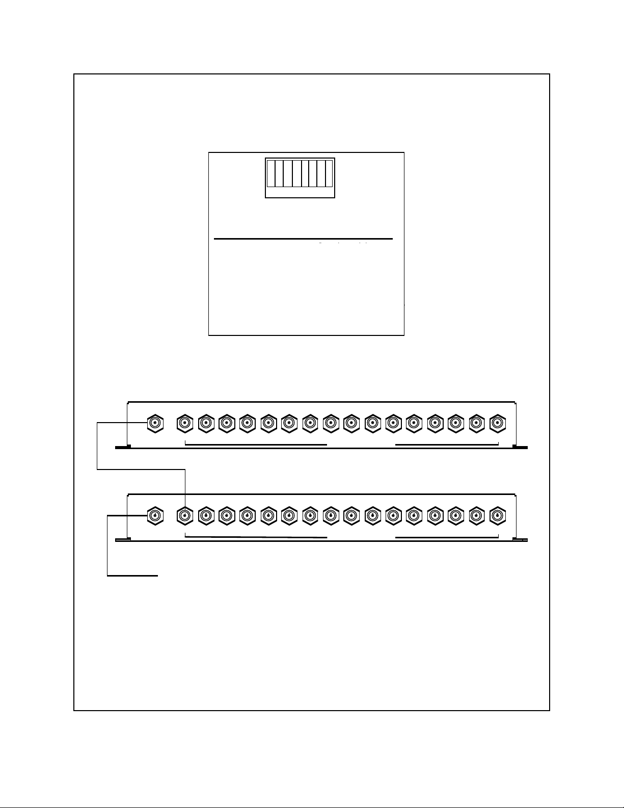
5. If multiple ICI3008/ICI3016 switchers are being cascaded, connect a coaxial cable from the last video
input of the first Inter-Check switcher to the port
labeled “VIDEO OUT” of the second Inter-Check
switcher. Remove the cover of the second InterCheck switcher and set the 8 position dip switch to
0001 0000. Remove the cover of the first InterCheck switcher and set the 8-position dip switch to
0000 1000 where 0 = ON and 1 = OFF (refer to
Figure 8).
6. Connect the desired alarm outputs to any peripheral
equipment requiring a normally open contact. (Refer
to Figure 5 for pin assignment information.)
7. Connect an “IBM AT” compatible keyboard into the
ICI3000P input labeled “KEYBOARD”.
8. Power up the Inter-Check units using the transformers
supplied with each unit.
9. To verify communication between the Inter-Check
switcher and the ICI3000P, press [F9]. Press [F9]
again. Next, select camera one by entering a [1] one
followed by the [ENTER] key. The first red light
labeled “1” on the first switcher should be on. Repeat
this step for each camera input on each switcher. If
an 8 or 16-position switcher has a second switcher
cascaded from it, selecting camera 8 or 16
respectively will cause the first light of the second
switcher to be activated.
!!!Defaults Loaded!!!
SYSTE M BEI NG I NI TI ALI ZED !
SYSTEM BEING INITIALIZED
PELCO
Press the [1] key on the keyboard for
PRESS 1 KEY ON KEYBOARD
approximately 3 seconds.
FOR APPROXI MATELY 3 SEC ONDS
ICI3000P by PELCO
Ver. 4 . 0
ROM Check = xxxx
ICI3000P BY PELCO
VE R . 4 . 0
Calc. ROM Check = yyyy
ROM CHE CK = XXXX
CALC. RO M CHE CK=YYYY
System Being Initialized
SYSTE M BEI NG I NI TI ALI ZED !
MM Ver. z.z
MM VE R . Z. Z
PELCO
Text on screen will flash
TEXT ON SCREE N WI L L F L ASH
IF DEFAUL T S WE R E L OADE D
if defaults were loaded.
Figure 3. Defaulting Inter-Check System
Pelco Manual C1043M-A (2/96) 5
Page 10
12
34 5678
1 2 3 4 5 6 7 8
OPE N
OPEN
DI P SWI TCH DES CRI P TI ON--
Swi t ch # Funct i on
1
2
3
4
5
6
7
8
B ank address
Bank Address
B ank address
Bank Address
B ank address
Bank Address
B ank address
Bank Address
Loop Select
l oop
baud rat e
NC
NC
sel ect
Baud Rate Select
NC
NC
sel ect
Co v e r mus t b eremoved t o access t his DIP Swi t c h
*
TO MONI
NOTE: Cover must be removed to access this dip switch.
CAMERAS 16- 31
CAMERAS 1 - 1 5
TOR ORVCR
Loop =
A ddr ess = 0001
VI DEO I NP UTS
Loop = 1
A ddr ess =
VI DEO I NP UTS
0
0000
Shadow switchers are available in either 8 or 16 positions.
12345678910111216 1 5 14 13VI D EO OUT
12345678910111216 1 5 14 13VI D EO OUT
Figure 4. Cascading the ICI30008 or ICI3016
6 Pelco Manual C1043M-A (2/96)
Page 11

3.3.1 Alarm Pin-out Configuration
For detailed 25-pin and 9-pin alarm pin-out configuration information, see Figure 5 below.
25-PIN CONNECTOR FOR ICI3016
13
1
25
14
Pin # Alarm Output
1Alarm Output 1
2Alarm Output 2
3Alarm Output 3
4Alarm Output 4
5Alarm Output 5
6Alarm Output 6
7Alarm Output 7
8Alarm Output 8
9Alarm Output 9
10 Alarm Output 10
11 Alarm Output 11
12 Alarm Output 12
13 Alarm Output 13
14 Alarm Output 14
15 Alarm Output 15
16 Alarm Output 16
17-25 Common Ground
9-PIN CONNECTOR FOR ICI3008
5 4 3 2 1
9 8 7 6
Pin # Alarm Output
1Alarm Output 5
2Alarm Output 7
3Alarm Output 6
4Alarm Output 8
5Alarm Output 1
6Alarm Output 3
7Alarm Output 2
8Alarm Output 4
9 Common Ground
Figure 5. Alarm Pin-Out Configurations
Pelco Manual C1043M-A (2/96) 7
Page 12
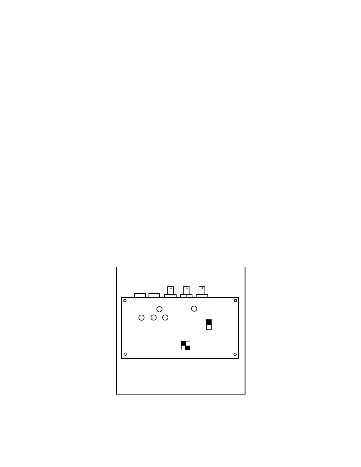
3.4 EXTERNAL VIDEO ADJUSTMENTS
There are five potentiometer adjustments located on the
bottom of the Inter-Check unit. These video text adjustments are for fine tuning only. Major adjustments
should be done through the operating software. Use a
small tipped, nonmetallic screwdriver for adjusting the
potentiometers on the bottom of the Inter-Check unit
(see Figure 6).
1. Adjust the HORIZONTAL SIZE of the te xt on your
monitor by rotating the potentiometer labeled “S”.
2. Adjust the INTENSITY of the text on your monitor
by rotating the potentiometer labeled “I”.
3. Adjust the HORIZONTAL POSITIONING of the
text on your monitor by rotating the potentiometer
labeled “H”.
4. Adjust the VERTICAL POSITIONING of the text
on your monitor by rotating the potentiometer labeled
“V”. If rotated fully counterclockwise the display
may “jitter”. A slight clockwise adjustment will
correct this problem.
5. Adjust the video GAIN of the monitor by adjusting
the potentiometer labeled “G”. This should be turned
all the way down for normal application.
6. Use the two DIP switches labeled "C" to adjust the
size of the characters.
7. To keep the programming from being changed or
lost, move the switch labeled “NV” into the locked
position. This will prevent the loss of programmed
settings in the case of power loss or battery failure.
G
H I V
S
Unlocked
Locked
NV Memory
Switch
C
Figure 6. Video Adjustment Locations
8 Pelco Manual C1043M-A (2/96)
Page 13

4.0 PROGRAMMING
4.1 REGISTER 1 OR 2 SELECT
To enter the SELECT MENU press enter. The following
menu will be displayed on monitor:
SELECT MENU
1. Register # 1 or 2
2. Operator # 1 or 2
3. Exceptions on/off
4. Camera select
5. Screen print on/off
6. Auto camera search on/off
7. Reverse video on/off
8. System program
9. Exceptions program
0. Syssave/Sysread
This menu allows you to manually display the transaction
data from a specific register on either Screen 1 (the lefthand side of the monitor) or Screen 2 (the right-hand side
of the monitor). (See Figure 7.) T o enter this menu, press
[1]. The monitor will display: Screen 1 or 2?
Select the screen (1 or 2) on which you want your register
data to be displayed and then press [Enter].
The next prompt is: Enter Register #_
Type in the Register number to be monitored. Press
[Enter]. Pressing [Enter] without selecting a Register
will turn off the previously selected screen. F or ICI3000P
installations, register numbers correspond to the address
of the ICI1000PIM installed within the register .
4.1.1 Register Selection Using the
Hot Key F1
To select a specific Register for monitoring while in the
monitoring mode:
1. Press [F1]
2. Select appropriate Screen # (no prompt is displayed):
Pressing [1] = Screen 1, Pressing [2] = Screen 2
S CRE EN # 1
OR
TEXT WI NDOW
#1
S CRE EN #
OR
T EXT WI NDOW
#22
PELCO
Figure 7. Inter-Check’s Two T e xt Screens
3. Select Register # or PIM NUMBER for monitoring.
4. Press [ENTER].
4.2 OPERATOR # 1 OR 2
This menu allows you to manually display the transaction
data from a specific operator on either Screen 1 (the lefthand side of the monitor) or Screen 2 (the right-hand side
of the monitor). T o enter this menu, press [2]. The monitor
will display: Screen 1 or 2?
Select the screen (1 or 2) on which you want your register
data to be displayed.
The next prompt is: Enter operator # OPR ??
Type in the operator number to be monitored (up to three
digits). Press [Enter]. Pressing [Enter] without
selecting an Operator will turn off the previously selected
screen.
Pelco Manual C1043M-A (2/96) 9
Page 14

4.2.1 Operator Selection Using
the Hot Key F2
• Press [3] to select internal synchronization (no
video).
To select a specific operator for monitoring while in the
monitoring mode:
1. Press [F2]
2. Select appropriate Screen # (no prompt is displayed):
Pressing [1] selects Screen 1
Pressing [2] selects Screen 2
3. Select operator number for monitoring.
4. Press [ENTER].
4.3 EXCEPTIONS ON/OFF
This function tells the Inter-Check unit whether or not
you want it to search for specific transactions that may
indicate fraudulent activity, known as “Exceptions”.
This works as a toggle switch.
•Press the [3] key to turn on the Exceptions. The
prompt, Exceptions on! will be displayed at the
top of the monitor.
•Pressing the [3] key again will turn off the Excep-
tions. The prompt, Exceptions off! will be displayed at the top of the monitor.
4.3.1 Exceptions On/Off Using the Hot
Key F3
To toggle the Exceptions on/off from the monitoring
mode, press [F3].
•Pressing F9 will enable you to select an external
camera from PELCO’s ICI3008/ICI3016 InterCheck switchers.
After pressing F9, the following prompt will be displayed:
Enter select #
Select camera number that corresponds to the
ICI3008/ICI3016 switcher.
4.4.1 Camera Select Using Hot
Key F9
From the monitoring mode:
1. Press [F9]
2. Select appropriate Video Input mode
1 = Video Input 1
2 = Video Input 2
3 = Internal Sync
F9 = Shadow List line item (To select an external
camera from ICI3008/ICI3016 Inter-Check switchers.)
4.5 SCREEN PRINT ON/OFF
This selection enables auxiliary serial printer port 1 on
the ICI3000P. To access this menu, press [5]. The following prompt will be displayed:
Screen 1 or 2?
Enter the screen number you wish to print.
4.4 CAMERA SELECT
This function is used to select a video input from the
ports labeled “VIDEO IN” on the ICI3000P, a selected
input from the ICI3008/ICI3016 camera list or no video
which is defined as internal sync.
To access this menu, press [4]. The following prompt
will be displayed: Camera 1, 2, 3 internal, F9 e xter-
nal
•Press [1] to select “VIDEO IN 1” on the back of the
ICI3000P.
•Press [2] to select “VIDEO IN 2” on the back of the
ICI3000P.
10 Pelco Manual C1043M-A (2/96)
4.5.1 Screen Print On/Off Using
Hot Key F4
From the monitoring mode:
1. Press [F4]
2. Select screen number to be printed
[1] = Screen 1
[2] = Screen 2
Page 15

4.6 AUTO CAMERA SEARCH ON/OFF
4.8 SYSTEM PROGRAM
When enabled, this feature monitors your camera
system’s sync generation. If your monitoring camera
loses power or is disconnected, the system will automatically switch to the next camera for synchronization. If an active video is not detected, the system will
automatically switch to “internal sync”. To enable the
Auto Camera Search feature, press [6]. Press [6] again
to turn off this feature.
4.6.1 Auto Camera Search On/Off
Using Hot Key F12
From the monitoring mode:
• Press [F12] to activate Auto Camera Search.
• Press [F12] again to deactivate Auto Camera Search.
4.7 REVERSE VIDEO ON/OFF
This feature changes the visual characteristics of the data
displayed by placing a black background around the video
characters.
• To enable the Reverse Video, press [7].
• To disable this feature press [7] again.
4.7.1 Reverse Video On/Off Using
Hot Key F10
From the monitoring mode:
1. Press [F10] to activate Reverse Video.
2. Press [F10] again to deactivate reverse video.
This menu is used for programming text displays;
communication and printer parameters; clock features;
camera selections and alarm dwell time.
To enter the System Menu, Press [8]. The following
menu will be displayed:
SYSTEM MENU
1. # Chars./line
2. # Lines for small scrn 1 or 2
3. Small scrn position 1 or 2
4. Large scrn position 1 or 2
5. Alarm dwell time
6. Channel parms
7. Printer parms
8. Set clock
9. Ext. cam. select
0. Shadow List
4.8.1 Number of Characters Per Line
Selecting 1 from the SYSTEM MENU enables you to
select the number of characters per line displayed on the
monitor.
Enter a number from 1-80 best suiting your application.
To access this menu, press [1]. The following prompt
will be displayed: Screen 1 or 2?
Enter the Screen number you wish to adjust. The following
prompt will be displayed:
# of characters = 40
Enter # of characters/line 1-80
• Enter the number of characters to be displayed.
• Press ENTER.
NOTE: The ICI3000P can only display 80 total
characters per line. Selecting 50 characters for
Screen 1 only allows 30 characters to be
displayed on Screen 2.
Pelco Manual C1043M-A (2/96) 11
Page 16

4.8.2 Number of Lines for Small
Screens 1 and 2
Using the cursor control keys, move the block to the
desired position on the monitor. Press [ENTER] to sa ve.
This feature enables you to select the number of data lines
displayed on each screen. The difference between the
“small” and “large” screens is that you may reduce the
number of lines displayed on the small screen, while the
large screen always displays 17 lines of text.
•To access this menu, press [2]. The following prompt
will be displayed: Screen 1 or 2?
• Enter the applicable screen, then press [Enter]. The
following prompt will be displayed:
# of lines = 5 Enter # of lines 1-17
• Enter the number of lines desired. Press [ENTER].
4.8.3 Small Screen Position 1 or 2
This feature enables you to position the displayed text on
the monitor. T o access this menu, press [3]. The following
prompt will be displayed: Screen 1 or 2?
Enter the screen number you wish to edit. The following
numbers will be displayed:
(Screen 1)
111111111111111111111111111111
111111111111111111111111111111
111111111111111111111111111111
111111111111111111111111111111
111111111111111111111111111111
NOTE: Overlapping the two screens will result
in “clipping” of the displayed text.
4.8.4 Large Screen Position 1 or 2
This feature enables you to position the text display of
your Large Screen option. This works the same way as
the previous small screen position function, except that
17 lines of data will always be displayed.
4.8.4.1 Large and Small Screen
Toggle Using Hot Key F7
• To toggle between Large and Small screen options,
press [F7] from the monitoring mode.
4.8.5 Alarm Dwell Time
This feature is used to set the amount of time the alarming
output stays activated after an alarm condition. To edit
this feature press [5]. The following prompt will be
displayed:
Screen 1 or 2?
• Screen 1 is linked to the #1 Alarm Output.
• Screen 2 is linked to the #2 Alarm Output.
• Enter the applicable screen number. The following
prompt will appear: Alarm dwell = 1
(Screen 2)
22222222222222222222222222222
22222222222222222222222222222
22222222222222222222222222222
22222222222222222222222222222
22222222222222222222222222222
NOTE: Only one of these blocks will appear
at one time.
This block represents the text normally displayed on the
monitor. The number of characters and lines displayed in
this block will correspond to the selections made in
Section 4.8.1 and 4.8.2. It also represents the current text
position on the monitor.
12 Pelco Manual C1043M-A (2/96)
• Enter an alarm dwell time 0-255
The default dwell time is set to 1 second. To change the
dwell time, enter the new dwell time in seconds. Press
[ENTER].
Page 17

4.8.6 Channel Program Menu
4.8.6.1 Partyline
Press [6]. The following prompt will be displayed:
CHANNEL PROGRAM MENU
4. Group Poll List
5. Exception Follow Alarm Time
6. Group Select
Exception Follow Alarm Time
This option is used to set the length of time the
Inter-Check unit will dwell on an exception when
using the Exception Follow or Hot Key E. When
this option is selected, the video screen will display:
Alarm Dwell = 10
Enter Alarm Dwell Time 0 - 255
4.8.6.2 Channel Program Menu
1. Baud Rate — Not Applicable
2. RS-232 — Not Applicable
3. ISO-Jack — Not Applicable
Group Poll List
This selection will allow you to edit the eightregister group you choose using Group Select in
the Channel Program group. This selection is used
if there are more than 16 registers in the system.
This list allows you to monitor any combination
of 16 registers.
For example, if you wish to monitor registers 1
through 8 plus registers 18 through 26, you would
select Group 2 using the Group Select menu option. Then select the Group Poll List menu option
and enter registers 18 through 26 to be monitored
in Group 2 rather than the default list which is 9
through 16.
The 16 registers to be monitored can also be selected using Hot Key G and Hot Key B while in
the monitoring mode.
Group Select
This option is used to choose a group of eight registers in the poll list that you want to edit using the
Group Poll List menu option.
Hot Key G is used to select one of the four groups
of eight registers. The status bar at the bottom of
the video screen will show which screen is currently selected. If Group 2 is selected, for example,
the status bar will read:
G4 = 2.
Similarly , if you wish to select a block of registers
(16 registers), press Hot Key B. If Block 2 is selected, for example, the status bar will read: B2 =
2. (Block 2 includes registers 17 through 32, which
is the same as Groups 3 and 4.)
Pelco Manual C1043M-A (2/96) 13
Page 18

4.8.7 Printer Parameters
4.8.9 External Camera Select
From this menu the baud rate for the auxiliary output port
may be adjusted to communicate with an optional serial
printer. The Inter-Check defaults to 9600 baud.
To edit the baud rate, press [7]. The following prompt
will appear:
Printer baud = 9600
Enter baud rate 1 - 19200?
Enter the desired baud rate for your printer.
Press [ENTER].
4.8.8 SET CLOCK
This function is used to set the internal clock to match
real time. To edit, press [8]. The following prompt will
be displayed:
1. Time
2. Date
• To set the time, press [1].
• Enter the correct military time separating each pair
of numbers by a colon.
• Press [ENTER] to save.
• To set the date, press [2].
• Enter the correct date separated by a slash.
• Press [ENTER] to save.
This feature selects the screen (1 or 2) to be used for
controlling the Inter-Check switcher . The selected screen
will have an “S” displayed at the bottom.
• To change the settings, press [9]. The monitor will
display: Screen 1 or 2?”
• Select the desired screen. The following prompt will
appear: 1. on 2. off
• Press [1] for screen on or [2] for screen off.
4.8.9.1 Equivalent Camera Select
Hot Key F9
1. Press [F9]
2. Select appropriate Video Input mode
1 = Video Input 1
2 = Video Input 2
3 = Internal Sync
OR - For manual external camera selection on an InterCheck Switcher:
1. Press [F9]
2. Press [F9] again
3. Select appropriate camera from the Shadow List:
[1] = Selects the camera programmed into Shadow
List preshot #1
[2] = Selects the camera programmed into Shadow
List preshot #2, etc.
DB25 CONNECTOR
PRI NTER
12345678910111213
14202122232425 19 1 8 161517
DB2 5 - BACK VI EW
PI N3 = RECEI VE ( Rx)
PI N7 = GRUND(
OGnd)
DB9 CONNECTOR
TO SMART
ICI3000P
UNI T
12345
6789
DB9 - BACK VI EW
PI N3 T ANSMI T ( Tx )
PI N5 = GROUND ( Gnd )
=R
Figure 8. DB25 Printer Connector to DB9 ICI3000P Unit Pin Assignments
14 Pelco Manual C1043M-A (2/96)
Page 19

4.8.10 Shadow List Programming
This list tells the 8- or 16-position Inter-Check Switcher
which camera and POS terminal are linked together . It is
also used to program sequential video switching. The [S]
hotkey is used to turn switcher sequencing on and off.
Press [0]. A long list of numbers will scroll up the screen.
The following prompt will appear:
30. 30 30
31. 31 31
32. 32 32
ESC to exit or ENTER to edit!
The default setting is thirty-two line items. If you have
already changed the programming, the list will stop with
the last programmed item.
•Press [Enter] to edit. The cursor should now be
under the REG” (for Register) column.
•Type in the number of your first Register, then press
[Enter].
REG CAM DWL
1.1 1
The cursor will move to the next column under CAM.
Enter the camera number on the Inter-Check switcher used
to capture video for your first register. Press [Enter].
REG CAM DWL
1.1 1 1
The cursor should now appear under the DWL column.
This is used for setting camera dwell time. Dwell time is
the amount of time in seconds that the video picture will
appear on the screen before switching to the next camera.
Enter the desired dwell time, then press [ENTER]. If
you want to skip a particular camera position during
sequencing, enter a zero for the camera dwell time.
NOTE: If you need to skip a line during
programming, press the [ESC] key. Pressing
the [ENTER] key will end your programming
session and return you to the System Menu.
Example 1:
Shadow List
REG CAM DWL
1. 115
2. 216
3. 324
4. 462
5. 5 9
During sequencing, with the above parameters set, the
following would occur:
1.Camera 1 would be selected for 5 seconds.
2.Camera 1 would be selected for 6 more seconds.
3.Camera 2 would be selected for 4 seconds.
4.Camera 6 would be selected for 2 seconds.
5. Since there is no dwell time programmed for camera
9, it will be skipped and sequencing will start over
from the beginning.
Example 2:
Shadow List
REG CAM DWL
1. 1 1
2. 225
3. 335
4. 445
Number one has nothing programmed under dwell time.
The Inter-Check unit interprets this as “we’ re at the end
of the sequence; go back to the beginning”. Since this
is the beginning, no sequencing takes place.
Each alarming output has its own dwell time. Alarm
output number two's dwell time is used for additional
functions, including switcher sequencing and exception hold time. If there are a number of conflicting commands asking for the “use” of the timer simultaneously ,
the timer determines priorities in the following order:
1. Alarm output timing
2. Exception hold (if exceptions are on)
3. Shadow switcher (if sequencing is on)
During an exception, the camera dwell time programmed above will also be used for the dwell time of
the alarm output. The preprogramming dwell time for
the alarm output is overridden during an exception.
Once the exception alarm has “timed out”, sequencing
will continue from that item in the shadow list.
Pelco Manual C1043M-A (2/96) 15
Page 20

4.9 EXCEPTIONS
Exceptions are cash register transactions of special interest
that can be programmed into the ICI3000P units. T ypical
transactions are V OID, REFUND, CASH P AID OUT and
NO SALE. These types of transactions can then be used
to alarm your VCR or other alarmable device for video
recording. Exceptions can also be printed out on an
external serial printer for immediate hard-copy evidence.
NOTE: Exceptions can only be displayed on
screen #2. Therefore, you cannot monitor a
register or operator number on screen 2 if
exceptions are used.
Press [9]. In the Main Menu and the following menu will
be displayed:
EXCEPTIONS MENU
1. Edit exception te xt
2. T ransaction Type
3. Del. Register Mask
4. Apply Register Mask
Press [1]. The following prompt will be displayed:
Enter text or (ESC) to exit, (DEL) to delete line,
(ENTER) to end line
1234567890123456789012345678901234567890
01==_
The “1234...” sequence of numbers serves as your guide.
As mentioned earlier these numbers are called an
Exception Column Line.
16 Pelco Manual C1043M-A (2/96)
Page 21

4.9.1 Exceptions using the
Column Specific Strategy
A Column Specific Exception is used to “flag” a
transaction according specific placement of text on the
register ticket. As an example, if the word VOID
normally appears starting 5 spaces from the left during
a void transaction, you would type in the following:
1234567890123456789012345678901234567890
01=>^^^^VOID
A. To find specific text placement on the screen, select
a register by selecting the [F1] key in the
monitoring mode and then press the [register
number], and then [Enter].
B. Turn on the exception column line by pressing the
[L] toggle key. The screen will now display:
1234567890123456789012345678901234567890
C. When you see the transaction come up on the
monitor’s screen, press the FREEZE toggle key
[F6]. This will stop the text from scrolling and
allow you to take a good, close look at the correct
placement of your particular transaction.
D. Write what you see on a piece of paper for a
programming reference. (You will need this
information when programming the information
you see now into the ICI3000P unit.) Use the
numbers above the text as a placement reference.
The example below will search data for any text in the
sixth position starting with D (Wildcard) SK.
Therefore, an exception will appear if the word DESK,
DISK, DUSK, or any other similar combination,
appears on the register.
1234567890123456789012345678901234567890
01=>^^^^D^SK
To accept this Column Specific caret situation press
[ENTER] at the end of the exception to save and
[ESC] to exit the Edit Exception Text menu.
4.9.2 Exceptions using the
Global Exception Strategy
A Global Exception is used to “flag” any text regardless
of the placement on the register receipt. Programming
is done by simply typing in the Exception you’re
interested in on the first line. An example of a VOID
Global Exception is shown below:
1234567890123456789012345678901234567890
01=>VOID
When you’re done, press [Enter] and the cursor will
jump down to the next line (02). At this point you can
either program in another Exception or press [ESC]
to exit. Up to 15 total Exceptions can be programmed
into your ICI3000P unit.
Use the [<Shift>] and [6] keys simultaneously to
produce the ^ (Caret) symbol (also used for wildcard
searches).
NOTE: When the caret symbol is used as
the first character of exception text, it causes
that line to become Column Specific. Also,
when the Caret is preceded by any other
character it will be recognized by Inter-Check
as a wildcard character. This means InterCheck will accept any character of text at that
point. Only ^ symbols used before your
Exception data will be recognized as column
dependent searches.
Pelco Manual C1043M-A (2/96) 17
Page 22

4.9.3 Exceptions Using the Price
Point Editing Strategy
This type of exception is used to program an exception
that is looking for characteristics in the actual price of the
item, rather than a specific word. The ke yboard character
used in this type of exception strategy is a double bar [ ]
and is displayed by pressing [<SHIFT>] [\]
simultaneously .
Follow these procedures for successful programming:
1. First determine the maximum number of digits that
your register system allows, and figure out where on
the exception column line scale the price’s decimal
point will be lined up. A good way to figure this
position out is to use the exception column line
feature in the monitoring mode. This is done by
pressing the [L] key in the monitoring mode while
ringing in the desired transaction on the register you
are currently monitoring.
Place a Caret symbol in front of your text to make it
Column-specific, and between text as a wildcard
symbol.
1234567890123456789012345678901234567890
03=>^^^^^Total:^^^^^^^
If you want your ICI3000P to look for numbers that are
greater than, less than, or equal to a set limit (i.e., any
total less than 0 or any transaction greater than $999),
follow the last double bar with a “Greater Than”, “Less
Than” or “Equal To” symbol. For example, if we want
Inter-Check to look for any total of $999 or greater, we
would program the following:
1234567890123456789012345678901234567890
03=>^^^^^Total:^^^^^^^0999.00 >
If you wanted Inter-Check to look for any neg ati ve total,
we would program the following:
1234567890123456789012345678901234567890
03=>^^^^^Total:^^^^^^^0000.00<
0000.00
1A. Select a register by selecting the [F1] key in the
monitoring mode, then press the [register number],
and then [Enter].
1B. Turn on the exception column line by pressing the
[L] toggle key. The screen will now display:
1234567890123456789012345678901234567890
1C. When you see the transaction come up on the
monitor’s screen, press the FREEZE toggle k ey [F6].
This will stop the text from scrolling and allow you
to take a good, close look at the correct placement of
your particular transaction.
1234567890123456789012345678901234567890
03=>Total: 9999.99 ^
(Decimal point at Second “2” position.
1D. Write what you see on a piece of paper for a
programming reference. (You will need this
information when programming the information you
see now into the ICI3000P unit.) Using the numbers
above the text as a placement reference.
1E. Enter the Edit Exception Text Menu once again.
2. Next, type in [0’s] for every digit allowed by your
Register system, preceding the first “0” with a double
bar (|) and following the last “0” with a double bar.
In this case, we are telling the ICI3000P to look for any
number “less than” 0000.00.
If you wanted Inter-Check to look for any total equal to
$999.00 program the following:
1234567890123456789012345678901234567890
03=>^^^^^Total:^^^^^^^0999.00
OR
1234567890123456789012345678901234567890
03=>^^^^^Total:^^^^^^^0999.00=
Equal is the default value so you don’t have to actually
insert the [=] sign after the double bar character. If you
decide to use the equal sign to be consistent, it will not
affect the operation of the Inter-Check unit.
NOTE: If you want to look for a total that is
less than another negative total (in other words,
more negative), use the negative total and the
less than sign.
In this example, we are looking for any total which shows
a refund greater than $2.00:
1234567890123456789012345678901234567890
03=>^^^^^Total:^^^^^^-0002.00< ^^
“Negative”
“Less Than”
18 Pelco Manual C1043M-A (2/96)
Page 23

4.9.4 Exceptions with
Descriptors
5.0 SUMMARY OF EXCEPTION
KEYBOARD DEFINITIONS:
If you would like to describe the type of Exception that is
being “flagged”, you can use a descriptor. As an example,
with our negative total, you may want Inter -Check to print
the following: “NEGATIVE TOTAL” following the
transaction. This is done by simply typing the
“Backslash” [\] key and the descriptor you want at the
end of the exception line (the last line of text or <, >,
or = sign).
Example 1:
1234567890123456789012345678901234567890123
03=>^^^^^Total:^^^^^^^0000.00<\NEGATIVE
TOT AL
In this example using the column specific and price
point exception strategies, Inter-Check will print
“NEGATIVE TOTAL” as a descriptor after every
transaction that is less than $0.00.
Please note that when programming descriptors or extra
text lines, this order/priority must be followed:
First: The exception price point or text and
its “definitions” such as (0000.00<)
or (VOID)
[ENTER] Saves any changes to one line of text in
the exception text editor.
[DEL] Deletes all characters to right of the cursor.
[ESC] Exits out of the edit exception text menu
back into the exceptions main menu.
[^]Wildcard or column specific character.
[\] Descriptor symbol
[|]Price point exception indicator
[SPACE]Inserts position spaces in the editing mode.
[=]Equal to a desired numerical value in price
point exceptions.
[>]Greater than a desired numerical value in
price point exceptions.
[<]Less than a desired numerical value in
price point exceptions.
Second: Any descriptors such as
(0000.00<\NEGATIVE TOTAL)
It’s important to recognize how your ICI3000P reads
certain parts of your exception line when you program
that information. The "|" character is recognized as
taking up one space on the exception text line. The ^,
<, >, or = characters are not. Any text entered after
these signs will be recognized by your Inter-Check unit,
when scanning for exceptions that are met, as being in
the position they occupy. Here’s an example:
1234567890123456789012345678901234567890
01=>^^^^^0000.00<N
You might say, at f irst glance, that Inter-Check will need
to see the letter “N” in the 15th position to recognize
this as an exception. In truth, the ICI3000P ignores the
position of the < sign, and “slides” the N over one space
to the 14th position. Please keep this in mind when
programming exception text that follows a price point.
[TAB] Has same function as the right arrow-
control key. Enables you to sequence
through each character on an exception
line which saves you the hassle of
reentering existing information on an
exception line.
[~]Tilde, used in conjunction with a + or -at
the end of an exception text causes the
display to print the 2 lines prior (-) or the
2 lines after (+) the exception.
Pelco Manual C1043M-A (2/96) 19
Page 24

5.1 REGISTER MASKING
This feature allows you to ignore exceptions when they
occur on certain registers. As an example, you may have
one register dedicated specifically to returns, so you’ll
want to ignore refund transactions at this register
because they occur constantly . The delete register mask
option works coincidentally with your programmed
exceptions. You will “link” certain exceptions to certain
registers with this feature.
Upon pressing [2], you’ll see the following prompt:
(1)=Edit list (2)=Edit link (ESC)=Exit
To edit the list, press [1] again. Y ou will see the prompt:
ESC to exit or ENTER to edit !
Press [ENTER], and the monitor will scroll a list of
item numbers. If none have been programmed, it will
just list the first item number:
1. ESC to exit or ENTER to edit !
Press [ENTER] again. The cursor will position itself
next to line item number one. Enter the register number
you want linked with an exception. Linking tells the
Inter-Check unit to ignore an exception for a selected
POS terminal. Up to 10 registers may be entered in the
edit list. Press [ESC] to skip a line. [ENTER] will
end the programming session.
To “link” the register and exception line together, from
the delete reg. Mask prompt you must press edit link
(2). Upon hitting 2 you will see the following:
1=Off 2=Off 3=Off 4=Off
5=Off 6=Off 7=Off 8=Off
9=Off 10=Off 11=Off 12=Off
13=Off 14=Off 15=Off 16=Off
ESC to exit or ENTER to edit !
You can enter up to 16 exceptions during exception
programming. Each one has a corresponding number,
which is represented on this screen. Use this feature to
tell Inter-Check which exception(s) you want linked to
your previous list of registers you programmed in. Upon
pressing [Enter] the monitor will display:
ESC to Link or CR to Unlink 1=Off
Do this for as many of your exceptions as you’d like. If
you had an exception you wanted to unlink or when
you are finished programming press [Enter].
This feature is similar to the delete register mask except
that it allows you to respond to an exception only if it is
linked to a register on this list.
Upon pressing [3], you’ll see the same kind of prompts
as you did with the delete register mask function:
(1)=Edit list (2)=Edit link (ESC)=Exit
Pressing [1] will allow you access to the apply register
mask list, which is configured the same as the delete
register mask list:
1. ESC to exit or ENTER to edit !
If you wish a particular exception to be accepted only
when it applies to a specific register, enter the register
number now at the first item number. Do this for as
many registers as you need. Again, you can enter up to
10 registers.
To link your register(s) to an exception, you must enter
the edit link function by pressing [2]. The procedure to
link the register and exception is exactly the same as in
the delete register mask sequence, except now you’re
telling Inter-Check: “Only when this exception is met
on this/these register(s), do I want it flagged as an
exception. Otherwise, ignore this exception”.
Please note that if an exception is not linked to either
the delete register mask or apply register mask function,
then it will be treated as a normal exception.
A register should never be linked to both the delete
register mask and apply register mask functions. If it
is, the delete register mask function will have priority.
5.2 SYS SAVE/SYS READ
Press the [0] key from the SELECTION MENU. Press
the [1] key (SYSSAVE). You may have to wait several
seconds to allow the Inter-Check to do the save. The
Inter-Check unit will beep once when it is done saving
your current parameters to nonvolatile memory.
If you would like exception number one to be “linked”
to the register(s) from your edit list, press [ESC]. The
Screen will change to:
ESC to Link or CR to Unlink 1=Off On 2=Off
20 Pelco Manual C1043M-A (2/96)
Page 25

6.0 HOT KEY SUMMARY LIST
[B] BLOCK SELECT
Used to select polling for a block of two (2) or four
(4) groups of registers.
[C][I] CLEAR COMMUNICATIONS
Clears Communication to PIMs and ICI3000P.
[E] EXCEPTION FOLLOW ON/OFF
The [E] key turns on the Exception Follow sequence
for Screen 1. When an exception occurs, the unit will
continue to monitor the POS terminal until an exception occurs on another terminal. When activ ated,
the following prompt will be displayed:
0000=EXF1>V S
If you wish to monitor a particular register while waiting for an Exception to happen you can simultaneously use the [F1] Hot Key. With Exception F ollow, both screens are used to look for Exceptions.
Remember, Exceptions must be turned on in order
for the [E] key to work.
[G] GROUP SELECT
Toggle between register groups 1 and 2, or 1 and 4.
[L] EXCEPTION COLUMN LINE ON/OFF
Turns on a row of numbers called an Exception Column Line which is used for programming Exceptions. This feature is especially useful when attempting to program Column Specific Exceptions.
[R] MAIN REGISTER for exception follow.
[S] SEQUENCING ON/OFF
The [S] key works as a toggle switch, turning on
and off the “Sequencing” of the Inter-Check switcher .
You can still use the hot key combination [F9], [F9]
to manually select an item from the Shadow List.
Each time you press the [S] key, Inter-Check will
beep and display a prompt informing you of the current settings.
[ESC] STANDBY MODE [ESC]
Puts the data in Standby mode and clears existing
data from the screen. This provides a clear view of
the video picture. [ENTER] returns to the monitoring mode. This function clears the communication
lines and buffers.
[F1] REGISTER SELECT
This function allows a specific register to be monitored continuously (see Section 4.1).
[F2] OPERATOR SELECT
This function allows a specific POS terminal operator to be continuously monitored (see Section 4.2).
[F3] EXCEPTIONS ON/OFF
This function turns on/off the exception monitoring
(see Section 4.3).
[F4] EXTERNAL PRINTER ON/OFF
This function turns on/off the external printer and
prints the text currently displayed on the monitor.
After pressing [F4], press [1] or [2] to select the
screen to be printed. A “P” will appear on the status
line of the screen you have selected. Inter-Check will
prompt: “Printer On” or “Printer Off” for current
printer status. Pressing [F4] and the screen number
again will turn off the printer as indicated by the disappearance of the “P”. The ICI3000P will only print
to the external printer for the last screen selected (see
Section 4.5).
[F5] PRINTER DUMP
This function is similar to the F4 function, except it
will print 40 lines of data previous to the current display. Printing will continue until turned of f. This feature is used for capturing important information that
may have scrolled off the screen.
[F6] FREEZE FRAME
This will “freeze” all action on the screen, both video
and data text. Pressing [F6] again will “unfreeze”
text.
[F7] SMALL SCREEN/LARGE SCREEN
TOGGLE
Depressing this key will toggle your data screen display from Small Screen T ext W indow parameters to
the Large Screen T ext Window parameters. Remember, you can program the number of lines you want
displayed for Small and Large Screen (Large screen
17 lines only .) (See Section 4.8.2 - 4.8.4).
Pelco Manual C1043M-A (2/96) 21
Page 26

[F8] PAGE BACK/PAGE FORWARD TOGGLE
This option allows you to look back one page of text
on your monitor to verify data. By using this key
you will automatically force the unit into large screen
mode. Pressing [F8] again will bring back the current page of text. The activ e page will sho w the cursor at the bottom of screen.
[F9] CAMERA SELECT
This function selects a video input from the ports
labeled “VIDEO IN” on the ICI3000P, a selected
input from the ICI3008/ICI3016 camera list or no
video which is defined as internal sync (see Section
4.4 and 4.8.9).
[F10] REVERSE VIDEO ON/OFF
This feature changes the visual characteristics of the
data displayed by placing a black background around
the video characters (see Section 4.7).
[F11] SCREEN DATA DUMP
This feature will send all data currently displayed on
the monitor and any data following to the printer.
No data will be displayed on the monitor until the
[F11] key is pressed again. In order to activate the
data dump, press [F11] followed by the desired
screen (1 or 2).
[F12] AUTO CAMERA SEARCH ON/OFF
Monitors camera system’s sync generation. If monitoring camera loses power or is disconnected, the
system will switch to the next camera for synchronization. If active video is not detected, the system will
switch to “internal sync” (see Section 4.6).
22 Pelco Manual C1043M-A (2/96)
Page 27

7.0 TROUBLESHOOTING
Problem: No video displayed on the monitor.
This section covers some basic troubleshooting
examples and possible solutions for each. Consult this
section first before calling your PELCO representative.
Problem: ICI3000P unit does not receive data.
Solution: Make sure that the data cable is plugged
into the DATA INPUT of the ICI3000P
unit. Check baud rate.
Problem: Inter-Check unit displays :
KEYBOARD TRANSMIT TIMEOUT
NO ACK FROM KEYBOARD
Solution: Make sure that your keyboard is IBM/
AT compatible.
Problem: Text on the right side of the screen
overlaps with text on the left side.
Solution: If using more than one camera (i.e.,
Shadow Switcher), make sure that your
auto camera search feature is turned OFF .
Refer to Section 4.8.10 for information
on how to operate this feature.
Turn on the monitor.
Check cabling and verify that the camera
and monitor cables are inserted into the
unit properly.
Problem: No power to the ICI3000P; the red power
LED indicator is not lit up.
Solution: Make sure power supply is plugged into
the unit properly.
Ensure that the outlet or power strip is
powered.
Solution: Your large and small text screens are set
up improperly. Refer to Sections 4.8.1-
4.8.4.
Problem: Printer prints strange characters
Solution: Make sure that the baud rate of the Inter-
Check unit matches the baud rate of the
printer. The unit defaults to 9600 baud
so the printer must also be programmed
for 9600 baud.
Problem: Vibrating text
Solution: Adjust the Video Gain potentiometer.
Problem: Text on screen 2 is being “cut off” on the
right side of the monitor.
Solution: Adjust the Size (S) potentiometer on the
bottom of the ICI3000P . T urn this control
all the way counterclockwise to achieve
the smallest character size. Refer to
Section 3.4 for a better description of this
feature.
Check the number of characters per line
you have programmed in for each screen.
Check Large and Small screen data
positions to ensure that they do not
overlap.
Pelco Manual C1043M-A (2/96) 23
Page 28

8.0 POWER-UP PROCEDURE FOR THE
ICI3000P
In the event of a power f ailure, the Inter-Check System
has a nonvolatile memory and will retain all memory
that has been previously saved. Some program functions, in order to be used, will have to be activated using the hot keys.
Following is a power-up procedure checklist to be followed in the event that the Inter-Check system experiences a power outage.
5. Check all programming to confirm that the memory
was retained. T o reenter any programming that may
have been lost, make sure that the NV switch on
the underside of the ICI3000P unit is in the “unlocked” position (i.e., away from the BNC connectors on the back of the unit. Lock the NV switch
when programming is complete.
6. Execute a “System Save” to retain programming
information. To exit out of the Monitoring Mode,
press “Enter”. Select the Menu and press [0] to
save.
1. Check all cables (power, video, data, alarm, etc.);
make sure all connections are intact.
2. Power down and then power up the ICI3000P to
make sure system defaults have loaded and initialized correctly.
3. Turn on the “Auto Camera” feature by pressing
[F12] or by pressing [Enter] from the select
menu and [6] to select Auto Camera ON. T urn the
video ON if the monitor is blank by pressing [P]
while in the Monitoring mode. Then press [F9]
again followed the camera in the Shadow List that
you wish to view.
4. Poll the ICI1000PIM units to make sure that they
are communicating by pressing [P] while in the
Monitoring mode. Then press [I] to initialize the
poll. If some units do not answer, check all system
cables for loose connections.
7. To reactivate the functions you need, use the Hot
Key Summary List on page 19 of the ICI3000P
manual. Press the corresponding Function Keys
(“S” to sequence, for example), while in the Monitoring Mode.
24 Pelco Manual C1043M-A (2/96)
Page 29

9.0 SPECIFICATIONS
Weight: 3 pounds
Dimensions: Length = 9.50 inches
Width = 5.75 inches
Height = 1.50 inches
Operating
Temperature: 35° F to 95° F
Storage
Temperature: -4° F to 140° F
Operating
Humidity: 20% to 80% non-condensing
ELECTRICAL SPECIFICATIONS:
Video Bypass: 5 volt dry contact relay passes video to
input 1
Switch: V ideo output upon power loss
DATA INPUT:
Keyboard Input: IBM/AT compatible - inputs f iltered with
470 ohm pullups and 220 pf. caps.
Alarming
Outputs 1 and 2: Optoisolated up to 3000 volts
Real Time
Clock: Y ear , Month, Day Hours, Minutes, Sec-
onds. Accurac y is approximately 2 seconds per year. Battery backup of 1 year
off load power or 2 year po wer on load
FCC Approved: This equipment has been tested with a
CLASS A computing de vice and has been found to comply
with part 15 of FCC rules. Operation in a residential area
may cause unacceptable interference to radio and TV reception requiring the operator to take whatever steps are necessary to correct the interference. (45 FR 24165, APR 9 1980)
Power Input: 5 volts DC ± 3%
Fused at 1.0 amps surge
Power Supply:
120 volts A C @ 15 watts in - 60 Hz
5 volts DC @ 1.0 amps out
5% line load regulation
Frequency: 50 Hz - 60 Hz.
Video Inputs: (2) 75 ohm NTSC/PAL, BNC Connect
Video Output: (1) 75 ohm NTSC/P AL, BNC Connect
Camera Switch: Switch on vertical of displayed signal.
Dwell time accuracy = ± .1 second
Internal
Standard Option: Composite NTSC
Battery type: Lithium type, 3 volts @ 160 MA
Non-Volatile
Memory: May be corrupted by large magnetic
fields or x-rays. Write protected switch
for power surges and intermittents
Video Character
Display: Standard Option: Max. of 17 lines per
screen. Max. of 80 characters per line
Programmable
Exception
Flagging: 15 lines of exceptions possible.
10 Transaction types possible.
Each line may contain up to 60
characters.
Video Adjustment
Potentiometers:
(H) Horizontal position fine tune
(V) Vertical position fine tune
(S) Horizontal character size
(I) Character intensity
(G) Video Gain
Synchronization: Vertical = 60 Hz @ 260 µs
Horizontal = 15.36 KHz@ 4.38 µs
Alternate
PAL option: Vertical = 50 Hz @ 260 µs
Horizontal = 15.36 KHz @ 4.38 µs
Pelco Manual C1043M-A (2/96) 25
Page 30

9.1 OUTPUT DEFINITIONS
WIRE COLOR PIN DESIGNATION DESCRIPTION
White 1 +5 volts (For testing only)
Black 2 Signal Ground
Red 3 RS232 Current Loop
Green 4 NOT USED
Yellow 5 (Opto y-jack input)
Blue 6 NOT USED
AUXILIARY POR T 1 (Printer Port)
Communications = Standard RS232 Asynchronous
9600 Baud
8 bits
No Parity
CHANNEL 1 INPUT
ICI1000PIM Input for
CHANNEL 1
AUXILIARY PORT 2 (Shadow Switcher/Dome Port)
Communications = Standard RS232 Asynchronous
9600 Baud
8 Bits
No Parity
9.2 DB9 PINOUT
PIN # DESCRIPTION
1 NOT USED
2 RX AUX 1
3 (Printer port) TX A UX 1
4 NOT USED
5SIGNAL GROUND
6 NOT USED
7 RX AUX 2
8 (Dome-Shadow port) TX A UX 2
9 NOT USED
26 Pelco Manual C1043M-A (2/96)
Page 31

10.0 WARRANTY AND RETURN
INFORMATION
WARRANTY
Pelco will repair or replace, without charge, any merchandise proved
defective in material or workmanship for a period of one year after the date
of shipment.
Exceptions to this warranty are as noted below:
• Five years on FT/FR8000 Series fiber optic products.
• Three years on Genex
keyboard).
• Three years on Camclosure
CC3701H-2, CC3701H-2X, CC3751H-2, CC3651H-2X, MC3651H-2,
and MC3651H-2X camera models, which have a five-year warranty.
• Two years on standard motorized or fixed focal length lenses.
• Two years on Legacy
DF5/DF8 Series fixed dome products.
• Two years on Spectra
ing when used in continuous motion applications.
• Two years on Esprit
wiper blades).
• Eighteen months on DX Series digital video recorders, NVR300
Series network video recorders, and Endura
network-based video products.
• One year (except video heads) on video cassette recorders (VCRs).
Video heads will be covered for a period of six months.
• Six months on all pan and tilts, scanners or preset lenses used in
continuous motion applications (that is, preset scan, tour and auto scan
modes).
Pelco will warrant all replacement parts and repairs for 90 days from the
date of Pelco shipment. All goods requiring warranty repair shall be sent
freight prepaid to Pelco, Clovis, California. Repairs made necessary by
reason of misuse, alteration, normal wear, or accident are not covered
under this warranty.
Pelco assumes no risk and shall be subject to no liability for damages or
loss resulting from the specific use or application made of the Products.
Pelco’s liability for any claim, whether based on breach of contract,
negligence, infringement of any rights of any party or product liability,
relating to the Products shall not exceed the price paid by the Dealer to
Pelco for such Products. In no event will Pelco be liable for any special,
incidental or consequential damages (including loss of use, loss of profit
and claims of third parties) however caused, whether by the negligence
of Pelco or otherwise.
The above warranty provides the Dealer with specific legal rights. The
Dealer may also have additional rights, which are subject to variation from
state to state.
If a warranty repair is required, the Dealer must contact Pelco at (800) 2899100 or (559) 292-1981 to obtain a Repair Authorization number (RA),
and provide the following information:
1. Model and serial number
2. Date of shipment, P.O. number, Sales Order number, or Pelco invoice
number
3. Details of the defect or problem
If there is a dispute regarding the warranty of a product which does not fall
under the warranty conditions stated above, please include a written
explanation with the product when returned.
Method of return shipment shall be the same or equal to the method by
which the item was received by Pelco.
®
Series products (multiplexers, server, and
®
and fixed camera models, except the
®
, CM6700/CM6800/CM9700 Series matrix, and
®
, Esprit®, ExSite™, and PS20 scanners, includ-
®
and WW5700 Series window wiper (excluding
™
Series distributed
RETURNS
In order to expedite parts returned to the factory for repair or credit, please
call the factory at (800) 289-9100 or (559) 292-1981 to obtain an
authorization number (CA number if returned for credit, and RA number
if returned for repair).
All merchandise returned for credit may be subject to a 20% restocking
and refurbishing charge.
Goods returned for repair or credit should be clearly identified with the
assigned CA or RA number and freight should be prepaid. Ship to the
appropriate address below.
If you are located within the continental U.S., Alaska, Hawaii or Puerto
Rico, send goods to:
Service Department
Pelco
3500 Pelco Way
Clovis, CA 93612-5699
If you are located outside the continental U.S., Alaska, Hawaii or Puerto
Rico and are instructed to return goods to the USA, you may do one of the
following:
If the goods are to be sent by a COURIER SERVICE, send the goods to:
If the goods are to be sent by a FREIGHT FORWARDER, send the goods
to:
Pelco
3500 Pelco Way
Clovis, CA 93612-5699 USA
Pelco c/o Expeditors
473 Eccles Avenue
South San Francisco, CA 94080 USA
Phone: 650-737-1700
Fax: 650-737-0933
Pelco, the Pelco logo, Camclosure, Esprit,
Genex, Legacy, and Spectra are registered
trademarks of Pelco.
Endura and ExSite are trademarks of Pelco.
© Copyright 1996, Pelco. All rights reserved.
Pelco Manual C1043M-A (2/96) 27
Page 32

®
PELCO
3500 Pelco Way
Clovis, CA 93612-5699 USA
(559) 292-1981 • (800) 289-9100
FAX (800) 289-9150 or (559) 292-3827
International customers call 1-559-292-1981
or FAX 1-559-348-1120
(Product specifications subject to change
without notice.)
C1043M-A
28 Pelco Manual C1043M-A (2/96)
 Loading...