

Page 1
®
20131
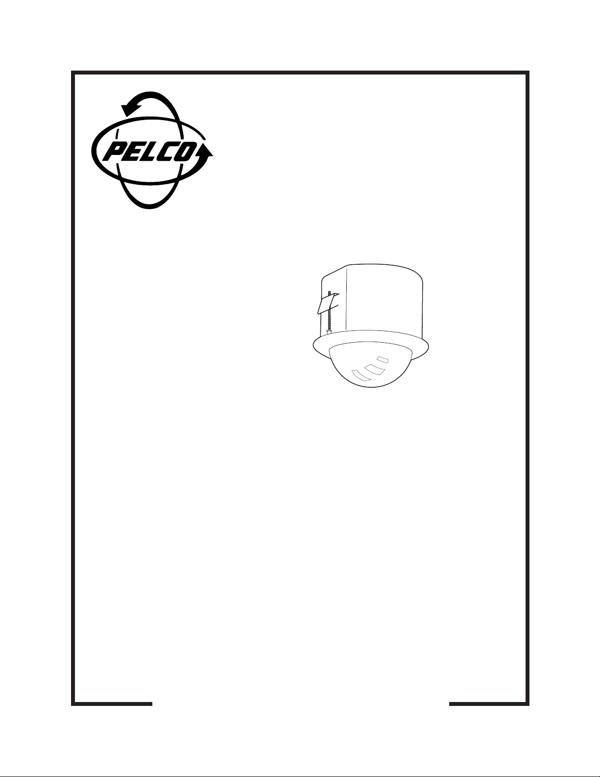
BBDF5-F, BBDF5L-F,
and BBDF5S-F
Back Boxes
Installation/
Operation Manual
C1496M-A (2/02)
Pelco • 3500 Pelco Way • Clovis, CA 93612-5699 USA • www.pelco.com
In North America and Canada: Tel (800) 289-9100 • FAX (800) 289-9150
International Customers: Tel +1(559) 292-1981 • FAX +1(559) 348-1120
Page 2

CONTENTS
LIST OF TABLES
Section Page
IMPORTANT SAFEGUARDS AND WARNINGS ................................................................ 3
DESCRIPTION ................................................................................................................... 3
MODELS ....................................................................................................................3
INSTALLATION ..................................................................................................................3
HARD CEILING INSTALLATION ............................................................................... 4
SUSPENDED CEILING INSTALLATION ................................................................... 5
CAMERA AND LENS INSTALLATION ....................................................................... 6
SPECIFICATIONS.............................................................................................................. 7
WARRANTY AND RETURN INFORMATION..................................................................... 8
Table Page
A Video Coaxial Cable Requirements ................................................................... 6
B 24 VAC Wiring Distances ................................................................................... 6
2 Pelco Manual C1496M-A (2/02)
Page 3
IMPORTANT SAFEGUARDS AND WARNINGS
Prior to installation and use of this product, the following WARNINGS should be observed.
1. Installation and servicing should only be done by qualified service personnel and conform to all local codes.
2. Unless the unit is specifically marked as a NEMA Type 3, 3R, 3S, 4, 4X, 6 or 6P enclosure, it is designed for indoor use only and it must not be installed where exposed
to rain and moisture.
3. Only use replacement parts recommended by Pelco.
4. After replacement/repair of this unit’s electrical components, conduct a resistance
measurement between line and exposed parts to verify the exposed parts have not
been connected to line circuitry.
5. The installation method and materials should be capable of supporting four times the
weight of the unit and equipment.
The product and/or manual may bear the following marks:
This symbol indicates that dangerous voltage constituting a risk of electric shock is
present within this unit.
This symbol indicates that there are important operating and maintenance instructions
in the literature accompanying this unit.
Please thoroughly familiarize yourself with the information in this manual prior to installation and operation.
CAUTION:
RISK OF ELECTRIC SHOCK.
DO NOT OPEN.
DESCRIPTION
The BBDF5-F, BBDF5L-F, and BBDF5S-F are plenum rated back boxes that can be installed in hard ceiling or standard 2' x 2' (61 x 61 cm) suspended ceiling. The BBDF5-F
and BBDF5L-F require 5.25 inches (13.34 cm) of space above the ceiling, and the
BBDF5S-F needs only 2.75 inches (7 cm) of room.
MODELS
BBDF5-F Standard in-ceiling back box
BBDF5L-F Extended in-ceiling box
BBDF5S-F Shortened in-ceiling box
INSTALLATION
CONTENTS
1 Back box with tilt table assembly installed (includes camera and lens if specified with order)
1 Parts bag
1 Conduit fitting with lock nut
1 Safety chain bracket
1 3-inch miniature coaxial cable assembly
1 Compass tool
1 Flat washer (models without camera)
1 Split lock washer (models without camera)
1 Screw (models without camera)
Pelco Manual C1496M-A (2/02) 3
Page 4

HARD CEILING INSTALLATION
1 PREPARE CEILING
Locate the center point of the mounting location. Drill a hole in the ceiling using a 3/32inch drill. Insert the compass tool into the hole. Use a pencil and the compass tool to
draw a circle on the ceiling. Carefully cut out the circle.
20116
20122
20120
20124
2 INSTALL THE BACK BOX
Attach the conduit fitting, lock nut, and safety chain bracket. Install a safety chain/
cable (not supplied) that will support up to 16 pounds (7.3 kg). Install one end of the
safety chain/cable to the safety chain bracket and the other end to a support structure
in the ceiling.
Prepare the wiring for camera and lens power; refer to Tables A and B for wiring
distances. Pull wiring into the back box through the conduit fitting.
Compress the spring clips on the back box and push it through the hole until the clips
spring back. Tighten the screws until you hear a clicking noise.
ATTACH SAFETY CHAIN HERE
CEILING
20125
CEILING
20127
20126
4 Pelco Manual C1496M-A (2/02)
Page 5

NOTE:
The ceiling tile
cannot be thinner than
0.50-inch (1.27 cm) or
thicker than 1.75 inches
(4.45 cm).
SUSPENDED CEILING INSTALLATION
1 PREPARE CEILING TILE
Remove the ceiling tile from the ceiling. Insert the compass tool (supplied) into the
center of the tile.
(If necessary, use a 3/32-inch bit to drill a hole.) Draw a circle on the tile using the
compass tool and a pencil. Carefully cut out the circle.
20128
20129
2 INSTALL THE BACK BOX
Attach the conduit fitting, lock nut, and safety chain bracket. Attach to the bracket one
end of a safety chain/cable (not supplied) that will support up to 16 pounds (7.3 kg).
Do not attach the other end yet.
Compress the spring clips on the back box and push it through the hole until the clips
spring back. Tighten the screws until you hear a clicking noise. Reinstall the ceiling tile.
Remove an adjacent ceiling tile. Prepare the wiring for camera and lens power; refer to
Tables A and B for wiring distances. Pull wiring into the back box through the conduit
fitting. Attach the safety chain to a support structure. Replace the adjacent ceiling tile.
CEILING
20119
ATTACH SAFETY CHAIN HERE
CEILING
20118
20127
20125
Pelco Manual C1496M-A (2/02) 5
Page 6

Table A. Video Coaxial Cable Requirements
Cable Type* Maximum Distance
RG59/U 750 ft (229 m)
RG6/U 1,000 ft (305 m)
RG11/U 1,500 ft (457 m)
* Minimum cable requirements:
75 ohms impedance
All-copper center conductor
All-copper braided shield with 95% braid coverage
Table B. 24 VAC Wiring Distances
The following are the recommended maximum distances for 24 VAC
with a 10-percent voltage drop. (Ten percent is generally the maximum
allowable voltage drop for AC-powered devices.)
Wire Gauge
Total vA 20 18 16 14 12 10
10 vA 283 ft 451 ft 716 ft 1142 ft 1811 ft 2880 ft
(86) (137) (218) (348) (551) (877)
CAMERA AND LENS INSTALLATION
NOTE:
If the camera and
lens are already installed,
refer to the camera and lens
manuals for information on
wiring and operating your
equipment.
To install the camera and lens:
1 Install the miniature coaxial cable on the camera. Attach the camera and lens to the tilt
table with the 1/4-20 screw and washers (supplied).
20130
2 To ensure that the lens will not hit the lower dome:
• Place the lower dome over the back box with the camera and lens installed (do not
attach dome).
• If the lens touches the lower dome, adjust the tilt table assembly.
3 Refer to the manual supplied with the camera and lens for the following information:
• How to connect power and video wiring
• How to make camera and lens adjustments
6 Pelco Manual C1496M-A (2/02)
Page 7

SPECIFICATIONS
MECHANICAL
Construction
Back Box: Aluminum
Mounting Bracket: Steel
Dimensions: See dimension drawings
GENERAL
Environment: Indoor and outdoor
Operating Temperature: 32° to 120°F (0° to 49°C)
Weight:
BBDF5-F: 2.80 lb (1.27 kg)
BBDF5L-F 3.00 lb (1.36 kg)
BBDF5S-F: 1.75 lb (.80 kg)
(Design and product specifications subject to change without notice.)
7.6
(19.33)
7.25 (18.13)
6.60 (16.76)
2.75
(6.99)
7.25 (18.13)
6.60 (16.76)
5.3
(13.34)
7.25 (18.13)
6.60 (16.76)
BBDF5L-F BBDF5S-F BBDF5-F
NOTE: VALUES IN PARENTHESES ARE CENTIMETERS; ALL OTHERS ARE INCHES
Pelco Manual C1496M-A (2/02) 7
Page 8

PRODUCT WARRANTY AND RETURN INFORMATION
WARRANTY
Pelco will repair or replace, without charge, any merchandise proved defective
in material or workmanship for a period of one year after the date of shipment.
Exceptions to this warranty are as noted below:
• Five years on Pelco manufactured cameras (CC3500/CC3600 and MC3500/
MC3600 Series); two years on all other cameras.
• Three years on Genex® Series (multiplexers, server, and keyboard).
• Two years on cameras and all standard motorized or fixed focal length lenses.
• Two years on Legacy®, Camclosure™ Camera Systems, CM6700/CM6800/
CM8500/CM9500/CM9740/CM9760 Matrix, DF5 and DF8 Series Fixed Dome
products.
• Two years on Spectra®, Esprit™, and PS20 Scanners, including when used
in continuous motion applications.
• Two years on WW5700 series window wiper (excluding wiper blades).
• Eighteen months on DX Series digital video recorders.
• One year (except video heads) on video cassette recorders (VCRs). Video
heads will be covered for a period of six months.
• Six months on all pan and tilts, scanners or preset lenses used in continuous
motion applications (that is, preset scan, tour and auto scan modes).
Pelco will warrant all replacement parts and repairs for 90 days from the date of
Pelco shipment. All goods requiring warranty repair shall be sent freight prepaid
to Pelco, Clovis, California. Repairs made necessary by reason of misuse,
alteration, normal wear, or accident are not covered under this warranty.
Pelco assumes no risk and shall be subject to no liability for damages or loss
resulting from the specific use or application made of the Products. Pelco’s
liability for any claim, whether based on breach of contract, negligence, infringement of any rights of any party or product liability, relating to the Products shall
not exceed the price paid by the Dealer to Pelco for such Products. In no event
will Pelco be liable for any special, incidental or consequential damages (including loss of use, loss of profit and claims of third parties) however caused, whether
by the negligence of Pelco or otherwise.
The above warranty provides the Dealer with specific legal rights. The Dealer
may also have additional rights, which are subject to variation from state to state.
If a warranty repair is required, the Dealer must contact Pelco at (800) 289-9100
or (559) 292-1981 to obtain a Repair Authorization number (RA), and provide
the following information:
1. Model and serial number
2. Date of shipment, P.O. number, Sales Order number, or Pelco invoice number
3. Details of the defect or problem
If there is a dispute regarding the warranty of a product which does not fall
under the warranty conditions stated above, please include a written explanation with the product when returned.
Method of return shipment shall be the same or equal to the method by which
the item was received by Pelco.
RETURNS
In order to expedite parts returned to the factory for repair or credit, please call
the factory at (800) 289-9100 or (559) 292-1981 to obtain an authorization number (CA number if returned for credit, and RA number if returned for repair).
All merchandise returned for credit may be subject to a 20% restocking and
refurbishing charge.
Goods returned for repair or credit should be clearly identified with the assigned
CA or RA number and freight should be prepaid. Ship to the appropriate
address below.
If you are located within the continental U.S., Alaska, Hawaii or Puerto Rico:
Service Department
Pelco
3500 Pelco Way
Clovis, CA 93612-5699
If you are located outside the continental U.S., Alaska, Hawaii or Puerto Rico:
Intermediate Consignee Ultimate Consignee
American Overseas Air Freight Pelco
320 Beach Road 3500 Pelco Way
Burlingame, CA 94010 Clovis, CA 93612-5699
USA USA
REVISION HISTORY
Manual # Date Comments
C1495M 12/98 Original version.
C1496M-A 2/02 Added model BBDF5L-F and updated manual to new format.
® Pelco, the Pelco logo, Spectra, Genex, and Legacy are registered trademarks of Pelco. © Copyright 2002, Pelco
™ Esprit and Camclosure are trademarks of Pelco. All rights reserved.
8 Pelco Manual C1496M-A (2/02)
 Loading...