

Page 1
®
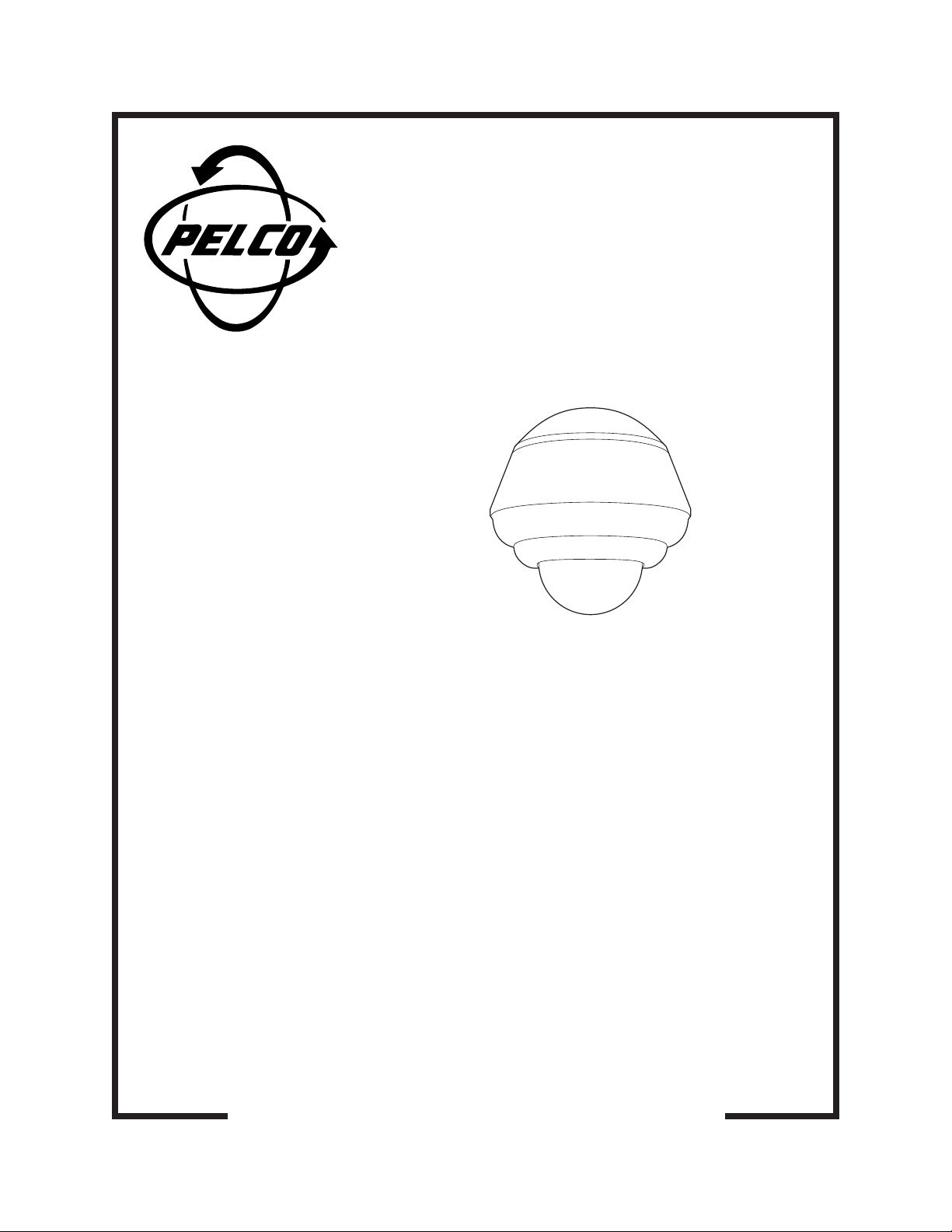
BB08 Series
Intercept
®
Back Box
Installation/
Operation Manual
C456M-D (1/98)
Pelco • 3500 Pelco Way • Clovis, CA 93612-5699 USA • www.pelco.com
In North America and Canada: Tel (800) 289-9100 or FAX (800) 289-9150
International Customers: Tel (1-559) 292-1981 or FAX (1-559) 348-1120
Page 2

CONTENTS
Section Page
1.0 GENERAL .................................................................................................. 3
1.1 IMPORTANT SAFEGUARDS AND WARNINGS ............................... 3
1.2 UNPACKING INSTRUCTIONS .......................................................... 4
1.3 RECOMMENDED TOOLS ................................................................. 4
2.0 DESCRIPTION ..........................................................................................5
2.1 MODELS ............................................................................................5
3.0 INSTALLATION ..........................................................................................6
3.1 SUSPENDED CEILING ..................................................................... 6
3.2 PENDANT ......................................................................................... 11
4.0 EXPLODED ASSEMBLY DIAGRAMS ...................................................... 13
5.0 SPECIFICATIONS ....................................................................................18
6.0 WARRANTY AND RETURN INFORMATION ........................................... 20
LIST OF ILLUSTRATIONS
Figure Page
1 “T-Bar” Clip Installation ....................................................................... 8
2 24 VAC Back Box Wiring Diagram ..................................................... 9
3 120 VAC Back Box Wiring Diagram .................................................. 10
4 BB08A120 Back Box Exploded Assembly Diagram.......................... 13
5 BB08E120 and BB08E211 Back Boxes Exploded Assembly Diagram ... 14
6 Back Plate Exploded Assembly Diagram.......................................... 16
7 BB08A120 Dimension Drawings ....................................................... 19
8 BB08E120 and BB08E211 Dimension Drawing ............................... 19
LIST OF TABLES
Table Page
A Video Coaxial Cable Requirements ................................................... 7
B 24 VAC Wiring Distances ...................................................................7
C BB08A120 Back Box Exploded Assembly Parts List (Figure 4) ........ 15
D BB08E120 and BB08E211 Back Boxes Exploded Assembly
Parts List (Figure 5) .......................................................................... 15
E Back Plate Exploded Assembly Parts List ........................................ 17
REVISION HISTORY
Manual # Date Comments
C456M 6/93 Original manual.
C456M 9/93 Addendum incorporated into manual to include updated
C456M 8/94 Manual revised to include updated wiring information.
C456M-A 6/95 Manual revised to include BOM quantity changes as per
6/95 Addendum. Incorporated new fuse and fuse holder into wiring
C456M-B 9/95 Manual revised to include sound quieting inserts as
C456M-C 4/96 Added Figure 16 and revised instructions for installing
C456M-D 1/98 Completely revised manual to reduce the number of
wiring diagrams as well as updated exploded view diagram.
ECO# 94-445; incorporated information on E-type white
finish available as per ECO# 95-013; included “front” label
information into BOM as per ECO# 94-192; also created
manual history and updated to new manual style.
diagrams and exploded view diagram as per ECO# 95-063.
standard feature, as per ECO# 95-356. Made BOM
changes as per ECO# 95-352.
optional backup plate per ECO# 96-061. Changed heater
specifications.
models and expand installation instructions. Incorporated
ECO# 97-364. Updated exploded assembly diagrams and
parts lists. Changed manual to new format and manual
pagination.
2 Pelco Manual C456M-D (1/98)
Page 3
1.0 GENERAL
1.1 IMPORTANT SAFEGUARDS AND WARNINGS
Prior to installation and use of this product, the following WARNINGS should be
observed.
1. Installation and servicing should only be done by Qualified Service Personnel
and conform to all Local codes.
2. Unless the unit is specifically marked as a NEMA Type 3, 3R, 3S, 4, 4X, 6, or
6P enclosure, it is designed for indoor use only and it must not be installed
where exposed to rain and moisture.
3. Only use replacement parts recommended by Pelco.
4. After replacement/repair of this unit’s electrical components, conduct a resistance measurement between line and exposed parts to verify the exposed
parts have not been connected to line circuitry.
5. The installation method and materials should be capable of supporting four
(4) times the weight of the enclosure, pan/tilt, camera and lens combination.
The product and/or manual may bear the following marks:
This symbol indicates that dangerous voltage constituting a
risk of electric shock is present within this unit.
This symbol indicates that there are important operating and
maintenance instructions in the literature accompanying this
unit.
CAUTION:
RISK OF
ELECTRIC SHOCK.
DO NOT OPEN.
TO REDUCE THE RISK OF ELECTRICAL SHOCK,
DO NOT REMOVE COVER. NO USER-
SERVICEABLE PARTS INSIDE. REFER SERVICING
TO QUALIFIED SERVICE PERSONNEL.
CAUTION:
Please thoroughly familiarize yourself with the information
in this manual prior to installation and operation.
Pelco Manual C456M-D (1/98) 3
Page 4

1.2 UNPACKING INSTRUCTIONS
Unpack and inspect all parts carefully.
Be sure to save the shipping carton and any inserts. They are the safest material in
which to make future shipments.
If an item appears to have been damaged in shipment, replace it properly in its
carton and contact the factory at 1-800-289-9100 or 1-559-292-1981 for a replacement. (International customers fax 1-559-348-1120 for authorization and instructions.)
If an item needs to be returned to the factory for repair, consult the WARRANTY
AND RETURN section of this manual for instructions.
The following items are supplied:
BB08A120 MODEL
1 Back box with face plate, trim ring, and dome
1 Parts bag
2 Eye bolts with nuts, flat washers and split lock washers
4 T-rail clips
1 Installation/Operation Manual (C456M-D)
BB08E120 and BB08E211 MODELS
1 Bezel with dome
1 Pendant cap
1 Back box
1 Parts bag with two O-rings (BB08E211 only)
1 Installation/Operation Manual (C456M-D)
1.3 RECOMMENDED TOOLS
Pelco does not supply basic tools needed for the installation process. The following
tools are recommended:
Medium Phillips screwdriver
Wire cutter
Wire stripper
BNC crimp tool
Coaxial cable stripper
Hammer and punch (suspended ceiling model only)
Large Phillips screwdriver (suspended ceiling model only)
11 mm wrench (suspended ceiling model only)
4 Pelco Manual C456M-D (1/98)
Page 5

The BB08 Series of back boxes is part of the IDS08 Intercept® Series of domes.
The IDS08 Series is an integral system that includes a back box (BB08), dome
drive (DD08), dome receiver/driver (DRD08), and imager/optics package (IOP08).
This manual covers the BB08 Series of back boxes. For installation and operation
instructions for the dome drive, refer to manual C416M-C; for the dome receiver/
driver, refer to C466M-E; and for the imager/optics package, refer to C1441M-C.
2.1 MODELS
2.0 DESCRIPTION
BB08A120 Indoor back box with smoked dome; 24 VAC input; installs in a
BB08E120 Indoor black pendant-mount back box with smoked dome.
BB08E211 Outdoor light gray pendant-mount back box with clear dome.
suspended ceiling. (CE, UL)
24 VAC input.
120 VAC input. Includes heater and fan. (UL)
Pelco Manual C456M-D (1/98) 5
Page 6

3.0 INSTALLATION
3.1 SUSPENDED CEILING
1. Remove the ceiling tile from the ceiling. If you are installing the back box into a
2' x 4' (61 x 122 cm) ceiling grid, cut the tile in half and install an additional “T”
bar for support. Reinstall one of the 2' x 2' (61 x 61 cm) sections.
2. Bring the wiring to the back box opening in the ceiling.
• Video - Refer to Table A for the type of video coaxial cable to use.
• Power - If the input power to the dome is 24 VAC, refer to Table B to
determine the size of wire to use. The power requirement is 48 vA.
• Control - If you are using a Coaxitron
operate the dome drive will be transmitted over the video coax.
If you are not using a Coaxitron
for two RS-485 control lines (RX+ and RX-).
®
controller, the control signals to
®
controller, bring wires to the back box
6 Pelco Manual C456M-D (1/98)
Page 7

Table A. Video Coaxial Cable Requirements
Cable Type* Maximum Distance
RG59/U 750 ft (229 m)
RG6/U 1,000 ft (305 m)
RG11/U 1,500 ft (457 m)
* Minimum cable requirements:
75 ohms
All-copper center conductor
All-copper braided shield with 95% braid coverage
Table B. 24 VAC Wiring Distances
The following are the recommended maximum distances for 24 VAC applications
and are calculated with a 10-percent voltage drop. (10-percent is generally the maximum allowable voltage drop for AC-powered devices.)
EXAMPLE:
An enclosure that requires 80 vA and is installed 35 feet
(10 m) from the transformer would
require a minimum wire gauge of 20
Awg.
NOTE:
Distances are calculated in
feet; values in parentheses are
meters.
Wire Gauge
20 18 16 14 12 10
10 283 451 716 1142 1811 2880
(86) (137) (218) (348) (551) (877)
20 141 225 358 571 905 1440
(42) (68) (109) (174) (275) (438)
30 94 150 238 380 603 960
(28) (45) (72) (115) (183) (292)
40 70 112 179 285 452 720
(21) (34) (54) (86) (137) (219)
50 56 90 143 228 362 576
(17) (27) (43) (69) (110) (175)
60
47 75 119 190 301 480
(14) (22) (36) (57) (91) (146)
70 40 64 102 163 258 411
(12) (19) (31) (49) (78) (125)
80 35 56 89 142 226 360
(10) (17) (27) (43) (68) (109)
90 31 50 79 126 201 320
(9) (15) (24) (38) (61) (97)
100 28 45 71 114 181 288
(8) (13) (21) (34) (55) (87)
110 25 41 65 103 164 261
(7) (12) (19) (31) (49) (79)
120 23 37 59 95 150 240
Total vA consumed
(7) (11) (17) (28) (45) (73)
130 21 34 55 87 139 221
(6) (10) (16) (26) (42) (67)
140 20 32 51 81 129 205
(6) (9) (15) (24) (39) (62)
150 18 30 47 76 120 192
(5) (9) (14) (23) (36) (58)
160 17 28 44 71 113 180
(5) (8) (13) (21) (34) (54)
170 16 26 42 67 106 169
(4) (7) (12) (20) (32) (51)
180 15 25 39 63 100 160
(4) (7) (11) (19) (30) (48)
190 14 23 37 60 95 151
(4) (7) (11) (18) (28) (46)
200 14 22 35 57 90 144
(4) (6) (10) (17) (27) (43)
Maximum distance from transformer to load
Pelco Manual C456M-D (1/98) 7
Page 8

3. To create an opening for the wiring, use a hammer and punch to remove one
of the knockouts in the top of the back box. If it is necessary to work inside the
back box, remove the trim ring and dome by inserting a screwdriver or your
fingers between the trim ring and the faceplate and popping the trim ring and
dome loose.
4. Remove the trim ring and dome (see step 3). Remove the parts bag inside the
back box. Reattach the trim ring and dome to the back box.
5. Angle the back box through the grid opening and set the back box into the
grid.
6. From an opening in a grid adjacent to the back box, install the four T-rail clips
that are supplied in the parts bag (refer to Figure 1).
7. If additional support is required (such as anchoring with a chain or steel cable
to a support beam above the dome enclosure), install one or both of the 1/420 eye bolts and washers that are supplied in the parts bag:
a. Remove one or two of the 1/4-20 screws in the top of the back box.
b. Screw a nut about a half inch onto an eyebolt.
c. Slide a split lock washer and flat washer onto the eyebolt.
d. Screw the eyebolt into the back box and lock the eyebolt into place by
tightening the nut with an 11 mm wrench.
e. Repeat steps b-d if you are going to install the second eyebolt.
f. Use a chain or cable to fasten the eyebolt(s) to a support structure in the
ceiling.
8. Remove the trim ring and dome.
Refer to Figure 2 for the following steps.
9. Push the wiring into the back box. If you are using conduit, fasten the conduit
to the back box.
10. Install the coaxial cable to the BNC connector.
11. Install power to the 10-position terminal block. Make sure the power switch on
the side of the back box is off.
Figure 1. “T-Bar” Clip Installation
8 Pelco Manual C456M-D (1/98)
Page 9

Figure 2. 24 VAC Back Box Wiring Diagram
Pelco Manual C456M-D (1/98) 9
Page 10

Figure 3. 120 VAC Back Box Wiring Diagram
10 Pelco Manual C456M-D (1/98)
Page 11

12. If you are not using Coaxitron® control, connect the control wiring to RXD+
and RXD-.
13. Back box installation is now complete. Proceed with the installation of the dome
drive unit. Refer to the manual provided with the dome drive for further installation instructions.
3.2 PENDANT
1. Install the pendant dome mount. Refer to the instructions supplied with the
mount.
From controller To 4-wire terminal inside back box
TXD+ RXD+
TXD- RXD-
NOTE:
The length of pipe may cause
noticeable motion on the video display. If this occurs, additional support
of the pipe by bracing, guy wiring, etc.
will be required.
2. The back box is designed to be suspended from a suitable length of 1-1/2"
NPT pipe threaded at both ends. For outdoor model, apply pipe thread sealant
to the pipe before assembly. Install one end of the pipe into the mount. Tighten
to approximately 30 ft/lb and tighten any locking means that may be provided
on the mount.
3. Bring the wiring for the back box through the mount.
• Video - Refer to Table A for the type of video coaxial cable to use.
• Power - If the input power to the dome is 24 VAC, refer to Table B to
determine the size of wire to use. For the 120 VAC model, make sure the
wiring can supply power for the heaters and fan as well as the receiver/
driver. Refer to Section 5.0, SPECIFICATIONS, for power requirements.
• Control - If you are using a Coaxitron® controller, the control signals to
operate the dome drive will be transmitted over the video coax.
If you are not using a Coaxitron® controller, bring wires to the back box
for two RS-485 control lines (RX+ and RX-).
4. Remove the parts bag inside the back box.
5. Outdoor Model Only - Place an O-ring onto the back box mounting pipe.
Push the O-ring up about 4 inches (10 cm) or as far as it will go if the pipe is
not 4 inches long.
6. Outdoor Model Only - Install the pendant cap on the pipe and place the top
side of the cap against the O-ring. Place the second O-ring onto the pipe and
push the O-ring against the bottom side of the pendant cap.
7. Back out the lock screw on the mounting flange of the back box so that the
back box can be screwed onto the mounting pipe.
8. Indoor Model Only - Place the pendant cap on top of the back box.
9. Screw the back box onto the mounting pipe. Tighten the lock screw.
10. Outdoor Model Only - Push the pendant cap down against the top of the
back box. Push the top O-ring against the top of the pendant cap.
Refer to Figure 3 for the following steps.
11. Install the coaxial cable to the BNC connector.
12. Install power to the 10-position terminal block. Make sure the power switch on
the side of the back box is off.
Pelco Manual C456M-D (1/98) 11
Page 12

13. If you are not using Coaxitron® control, connect the control wiring to RXD+
and RXD-.
From controller To 4-wire terminal inside back box
TXD+ RXD+
TXD- RXD-
14. The bezel and dome assembly can be attached to the back box at this time, or
it can be done after the dome drive is installed.
To install the dome drive, refer to the manual provided with the dome drive.
To attach the bezel and dome assembly to the back box, clip the safety cable
inside the bezel to the bracket just below the power switch inside the back box.
Let the bezel and dome assembly hang from the back box until the dome drive
is installed.
15. The back box installation is now complete. Proceed with the installation of the
dome drive unit. Refer to the manual provided with the dome drive for further
installation instructions.
12 Pelco Manual C456M-D (1/98)
Page 13

4.0 EXPLODED ASSEMBLY DIAGRAMS
A
E
F
2
3
5
7
B
4
C
D
6
8
1
Figure 4. BB08A120 Back Box Exploded Assembly Diagram
Pelco Manual C456M-D (1/98) 13
Page 14

Figure 5. BB08E120 and BB08E211 Back Boxes Exploded Assembly Diagram
14 Pelco Manual C456M-D (1/98)
Page 15

Table C. BB08A120 Back Box Exploded Assembly Parts List (Figure 4)
Item Quantity Description Part Number
1 1 Trim ring, white 8082ASSY
1 Dome seal (not shown) 80810007
1 Fixed dome, smoked (not shown) 80810008-4
1 Sound quieting ring (not shown) 8083001
2 1 Back box 8084297COMP
3 1 Face plate, drop ceiling, white 8084167COMP
4 1 Gland plate 8004130COMP
5 4 Ball stud receiver 90010030
6 4 T-rail retaining clip 80010008
7 1 Back box foam insert 8083000-1
8 Back box foam insert 8083000
1 Rocker switch, On/Off (not shown) SWI0201S11N41P
A 4 Screw, 1/4-20 x 3/8", pan head, Phillips ZH1/420X.375SPP
B 4 Split lock washer, 1/4" ZH1/4LWSSL
C 8 Nut, 6-32 ZH6-32NUTSH
D 8 Internal star washer, #6 ZH6LWSIS
E 2 Eye bolt, 1/4-20 x 2" ZH1/4-20X2.0EYE
F 2 Nut, 1/4-20 ZH1/4-20NUTCH
Table D. BB08E120 and BB08E211 Back Boxes Exploded Assembly Parts List (Figure 5)
Item Quantity Description Part Number
1 1 Black bezel assembly with smoked dome SQP0810000ASSY
Light gray bezel assembly with clear dome SQP0810011ASSY
2 1 Back box, textured black 8084195BCOMP
Back box, light gray 8084195GCOMP
3 1 Pendant cap, black 8084994COMP
Pendant cap, light gray 8084894COMP
4 3 Pin, bezel attachment 8004053COMP
5 3 Nylon spacer, flanged SPA3109
6 3 Compression spring SPRG10000
7 1 Flange, 1-1/2" NPT MRCA4000COMP
8 1 Gasket (BB08E211 only) 80010198
9 2 O-ring (BB08E211 only) 80010010
10 1 Safety cable E7081002COMP
11 1 Rocker switch, On/Off (not shown) SWI0201S11N41P
A 4 Screw 1/4-20 x 5/8" flat head, Phillips ZH1/420X.625SFS
B 3 Allen screw 6-32 x 1/4" ZH6-32X.250SS
Pelco Manual C456M-D (1/98) 15
Page 16

Figure 6. Back Plate Exploded Assembly Diagram
16 Pelco Manual C456M-D (1/98)
Page 17

Table E. Back Plate Exploded Assembly Parts List
Item Quantity Description Part Number
1 2 Latch backup plate 8004244COMP
2 2 Latch 8004105COMP
3 2 Latch bracket 8004143COMP
4 1 Transformer (120 VAC model only) TRF21243.30.70F
5 1 25-position connector plug CON10P025Z41T
6 2 Screw, 6-32 ZH208211-4
7 1 10-position terminal block TRB6TBV-10-OE
8 2 Alignment pin 8004402COMP
9 1 Heater/fan mounting bracket 8004118COMP
10 1 Fan, 120 VAC EH4600115W3
11 3 Heater, 120 VAC HTR50120
12 1 Back plate 8004190COMP
13 1 Connector mounting bracket 8004046COMP
14 2 Stabilizer bracket 8004047COMP
15 2 Boot 80010007
16 2 Hairpin clip ZH1/4CLIPSS
17 1 Connector, BNC jack, insulated CON01J002Z41S
18 6 2-position jumper TRBJ6-2
19 1 10-position terminal block cover TRBTC6-10-PFH
20 1 Thermostat (units with heaters and blower) EH5510049A
22 1 4-position terminal block TRB4-140
23 1 Fuse holder FUS357001
1 Fuse, 2A 3AG (not shown) FUS2
1 Capacitor, .47 µF, 12 V (not shown) CAPE474P012MAY
1 Capacitor, 220 µF, 100 V (not shown) CAPF221P100JRN
1 Capacitor, 270 µF, 100 V (not shown) CAPF271P100JRN
A 4 Screw, 10-32 x 1/2" flat head, Phillips ZH10-32X.500CFS
B 4 Split lock washer, 1/4" ZH1/4LWSSL
C 4 Nut, 1/4-20 ZH1/4-20NUTCH
D 10 Spacer .312 OD x 1/8" long, #10 SPA8540
E 2 Internal star washer, #10 ZH10LWSIS
F 2 Screw, 10-32 x 1" pan head, Phillips ZH10-32X1.00SPP
G 2 Nut, 6-32 ZH6-32NUTSH
I 2 Screw, 6-32 x 3/8" pan head, Phillips ZH6-32X.375SPP
J 4 Screw, 6-32 x 2" pan head, Phillips ZH6-32X2.00SPS
K 6 Spacer, 3/16" hex by 3/4" long, 2-56 tapped SPA9401L
L 4 Screw, 10-32 x 1/2" pan head, Phillips ZH10-32X.500SPP
M 2 Spacer, 1/4" hex by 1/2" long, 6-32 tapped SPA8423
N 2 Screw, 6-32 x 5/8" flat head, Phillips ZH6-32X.625SFS
O 4 Screw, 6-32 x 1/2" pan head, Phillips ZH6-32X.500SPP
Pelco Manual C456M-D (1/98) 17
Page 18

5.0 SPECIFICATIONS
ELECTRICAL
Enclosure Back Box
Input Voltage: 24 VAC or 120 VAC
Power Requirements
Receiver/Driver: 48 vA for 24 VAC and 120 VAC dome drives
Blower
(continuous duty): One (1) at 33 cfm, 6.7 watts, 120 VAC @ 60 Hz
Heaters
120 VAC: 135 watts total
Thermostatically controlled; activates ON at 40°F (4.4°C) and
OFF at 60°F (15.56°C)
Power Cord: Not supplied; use 3-wire grounded, 18 Awg minimum for 120
Power Cable: Not supplied; must conform to local and national electrical
GENERAL
Enclosure
Environment: Indoor or outdoor (depending on model ordered)
Dimensions: See Figures 7 and 8
Construction
Back box: Aluminum
Cap: Aluminum
Bezel: Aluminum
Trim Ring: ABS/aluminum
Finish
Outdoor: BB08E211 Light gray
Indoor: BB08A120 White (back box) and eggshell white (face
Temperature
Indoor Models: 32° to 120°F (0° to 48.89°C)
Outdoor Models: -10° to 120°F (-23.33° to 48.89°C)
VAC supply input
codes
plate, trim ring and bezel)
BB08E120 Black
(Design and product specifications subject to change without notice.)
This equipment contains electrical or electronic components that must be recycled properly to comply with Directive 2002/96/EC of the European Union
regarding the disposal of waste electrical and electronic equipment (WEEE). Contact your local dealer for procedures for recycling this equipment.
18 Pelco Manual C456M-D (1/98)
Page 19

NOTE: VALUES IN PARENTHESES ARE CENTIMETERS; ALL OTHERS ARE INCHES
Figure 7. BB08A120 Dimension Drawings
NOTE: VALUES IN PARENTHESES ARE CENTIMETERS; ALL OTHERS ARE INCHES
Figure 8. BB08E120 and BB08E211 Dimension Drawing
Pelco Manual C456M-D (1/98) 19
Page 20

6.0 WARRANTY AND RETURN INFORMATION
WARRANTY
Pelco will repair or replace, without charge, any merchandise proved defective in material or
workmanship for a period of one year after the date of shipment.
Exceptions to this warranty are as noted below:
Pelco, the Pelco logo, Camclosure, Esprit,
Genex, Legacy, and Spectra are registered
trademarks of Pelco.
Endura and ExSite are trademarks of Pelco.
© Copyright 1998, Pelco. All rights reserved.
• Five years on FT/FR8000 Series fiber optic products.
• Three years on Genex
• Three years on Camclosure
CC3751H-2, CC3651H-2X, MC3651H-2, and MC3651H-2X camera models, which have a fiveyear warranty.
• Two years on standard motorized or fixed focal length lenses.
• Two years on Legacy
dome products.
• Two years on Spectra
continuous motion applications.
• Two years on Esprit
• Eighteen months on DX Series digital video recorders, NVR300 Series network video
recorders, and Endura
• One year (except video heads) on video cassette recorders (VCRs). Video heads will be
covered for a period of six months.
• Six months on all pan and tilts, scanners or preset lenses used in continuous motion applications
(that is, preset scan, tour and auto scan modes).
Pelco will warrant all replacement parts and repairs for 90 days from the date of Pelco shipment.
All goods requiring warranty repair shall be sent freight prepaid to Pelco, Clovis, California. Repairs
made necessary by reason of misuse, alteration, normal wear, or accident are not covered under
this warranty.
Pelco assumes no risk and shall be subject to no liability for damages or loss resulting from the
specific use or application made of the Products. Pelco’s liability for any claim, whether based on
breach of contract, negligence, infringement of any rights of any party or product liability, relating
to the Products shall not exceed the price paid by the Dealer to Pelco for such Products. In no event
will Pelco be liable for any special, incidental or consequential damages (including loss of use, loss
of profit and claims of third parties) however caused, whether by the negligence of Pelco or
otherwise.
The above warranty provides the Dealer with specific legal rights. The Dealer may also have
additional rights, which are subject to variation from state to state.
If a warranty repair is required, the Dealer must contact Pelco at (800) 289-9100 or (559) 292-1981
to obtain a Repair Authorization number (RA), and provide the following information:
1. Model and serial number
2. Date of shipment, P.O. number, Sales Order number, or Pelco invoice number
3. Details of the defect or problem
If there is a dispute regarding the warranty of a product which does not fall under the warranty
conditions stated above, please include a written explanation with the product when returned.
Method of return shipment shall be the same or equal to the method by which the item was received
by Pelco.
RETURNS
In order to expedite parts returned to the factory for repair or credit, please call the factory at (800)
289-9100 or (559) 292-1981 to obtain an authorization number (CA number if returned for credit,
and RA number if returned for repair).
All merchandise returned for credit may be subject to a 20% restocking and refurbishing charge.
Goods returned for repair or credit should be clearly identified with the assigned CA or RA number
and freight should be prepaid. Ship to the appropriate address below.
If you are located within the continental U.S., Alaska, Hawaii or Puerto Rico, send goods to:
If you are located outside the continental U.S., Alaska, Hawaii or Puerto Rico and are instructed
to return goods to the USA, you may do one of the following:
If the goods are to be sent by a COURIER SERVICE, send the goods to:
Service Department
Pelco
3500 Pelco Way
Clovis, CA 93612-5699
Pelco
3500 Pelco Way
Clovis, CA 93612-5699 USA
If the goods are to be sent by a FREIGHT FORWARDER, send the goods to:
Pelco c/o Expeditors
473 Eccles Avenue
South San Francisco, CA 94080 USA
Phone: 650-737-1700
Fax: 650-737-0933
®
Series products (multiplexers, server, and keyboard).
®
and fixed camera models, except the CC3701H-2, CC3701H-2X,
®
, CM6700/CM6800/CM9700 Series matrix, and DF5/DF8 Series fixed
®
, Esprit®, ExSite™, and PS20 scanners, including when used in
®
and WW5700 Series window wiper (excluding wiper blades).
™
Series distributed network-based video products.
20 Pelco Manual C456M-D (1/98)
 Loading...