


Car receiver PY-9398
2 / IN T1 /
B N D
6 / +1 0
5 / -1 0
3 / R P T
4 / RD M
A M S
M D
D IS P
M U
Owner’s manual
A U X
PY-939 8
EN
Bedienungsanleitung DE
Instrukcja obsługi PL
Manual de utilizare
RO


Owner’s manual
ITEM
Installation 4
Wire connection diagram 6
Front panel 7
General operations 8
Radio operations 10
RDS Operations 12
Bluetooth Operations 13
Remote control layout 14
Specication 16
EN
3

Owner’s manual
PRECAUTIONS
Choose the mounting location where the unit will not interfere with the normal driving function of
the driver.
Before nally installing the unit, connect the wiring temporarily and make sure it is all connected
up properly and the unit and the system work properly.
Use only the parts included with the unit to ensure proper installation. The use of unauthorized
parts can cause malfunctions.
Consult with your nearest dealer if installation requires the drilling of holes or other modications
of the vehicle.
Install the unit where it does not get in the driver‘s way and cannot injure the passenger if there is
a sudden stop. Like an emergency stop.
Avoid installing the unit where it would be subject to high temperature, such as from direct sunlight, or from hot air, form the heater, or where it would be subject to dust, dirt or excessive vibration. Do not expose this equipment to rain or moisture.
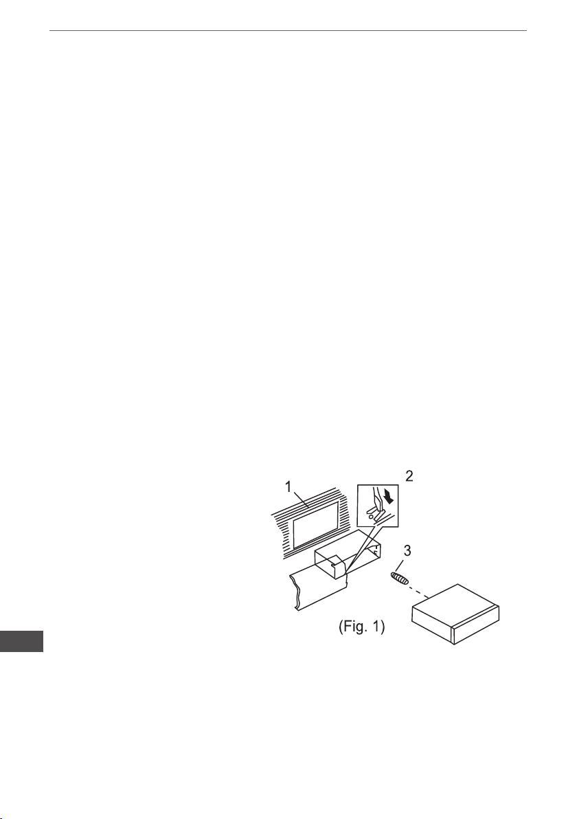
DIN FRONT-MOUNT (Method A)
Installing the unit
1. Dashboard
2. Holder
After inserting the holder into the
dashboard, select the appropriate tab according to the thick-
ness of the dashboard material
and bend them inwards lo secure
the holder in (Fig. 1) place.
3. Screw
EN
4
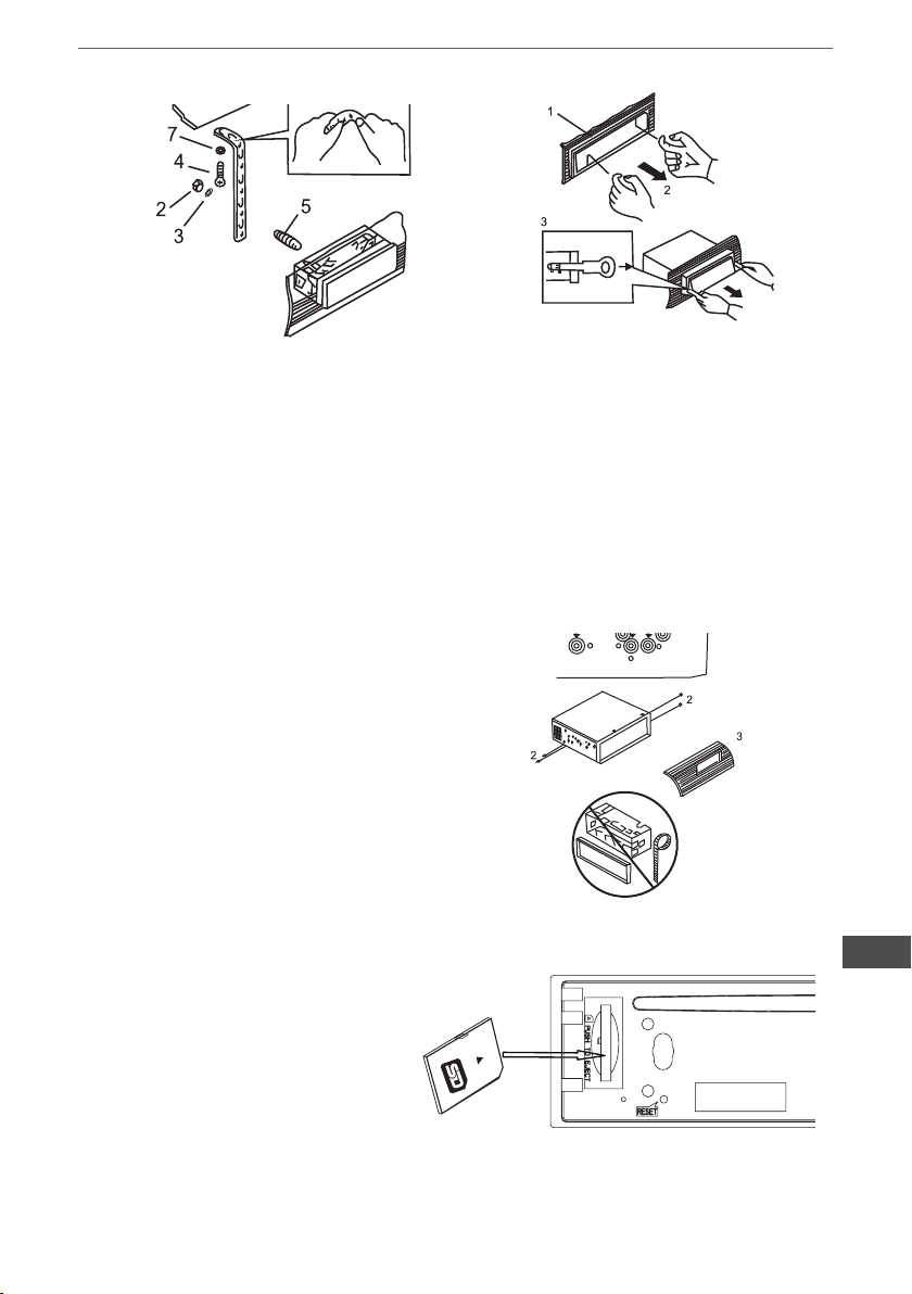
Fig.2
Owner’s manual
Fig.3
1. Dashboard
2. Nut(5 mm)
3. Spring Washer
4. Screw (5x25rnm)
5. Screw
6. Strap
Be sure to use the strap to secure the back of the unit in place.
The strap can be bent by hand to
the desired angle.
7. Plain Washer
DIN REAR-MOUNT (Method B)
Installation using the screw holes on the
sides of the unit
Fastening the unit to the factory
radio mounting bracket:
1. Select a position where the screw holes
oft he bracket and the screw holes of the
main unit become aligned (are tted), and
tighten the screws at 2 places on each
side. Use either truss screws (5 >< 5mm)
or ush surface screws (4 x 5mn1)
2. Screw
3. Dashboard or Console
INPUT THE SD CARD
The SD oblique angle keeps
Rightward exposure, put into the
SD slot and press it again to eject.
1. Frame
2. Insert ngers into the groove in the front
of frame and pull out to remove the frame.
(When reattaching the frame, point the side
with a groove downwards and attach it.)
3. Lever
Insert the levers supplied with the unit into
the grooves at both sides of the unit and
shown in gure until they click. Pulling the
levers makes possible to remove the unit
from the dashboard.
EN
5
Owner’s manual
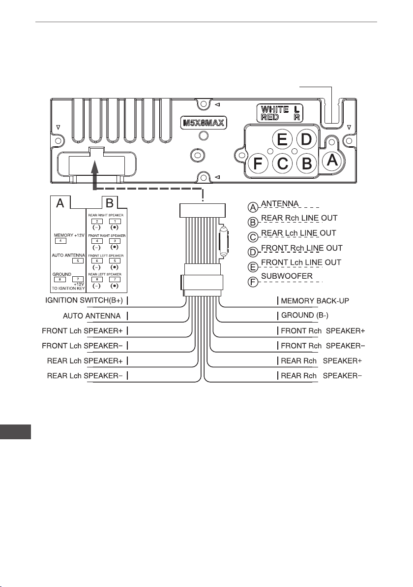
WIRE CONNECTION DIAGRAM
BLUETOOTH ANTENNA
15 A
EN
6
RE D YE LL OW
BL UE
WH IT E
WH IT E/ BL A CK
GR EE N
GR EE N/ BL A CK
VI OL ET /BL AC K
BL AC K
GR EY
GR EY /B L AC K
VI OL ET
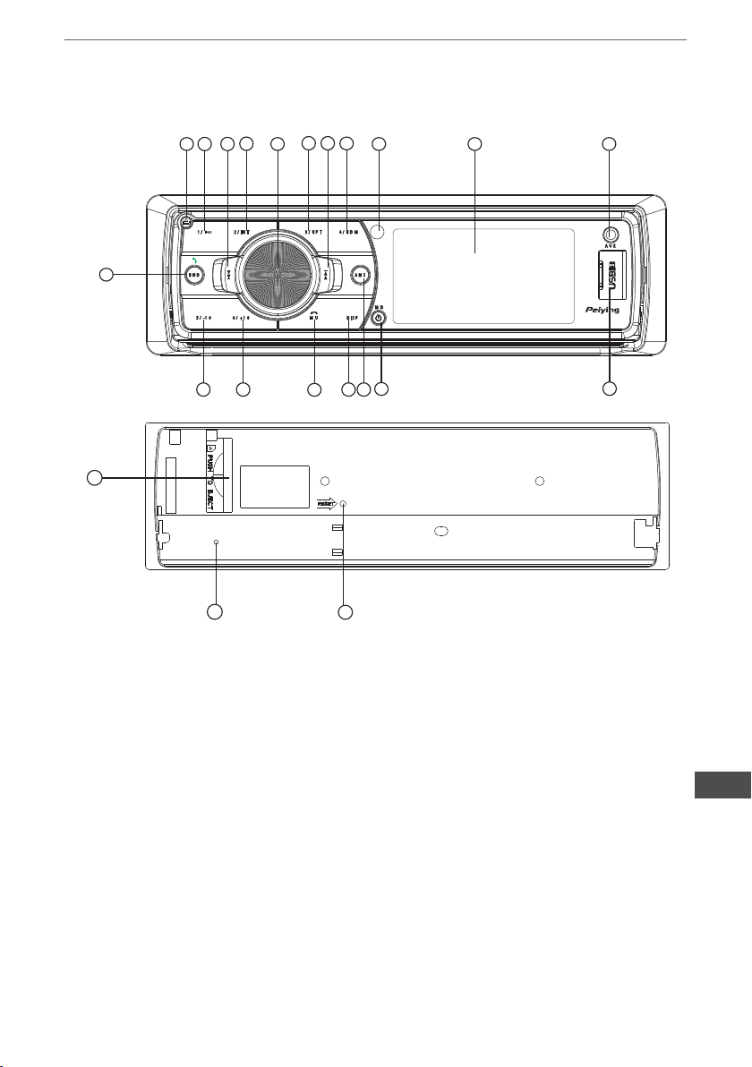
FRONT PANEL LAYOUT
14
11
13
2
3
Owner’s manual
10
15
16
19
6
22
2 / IN T1 /
9
21
B N D
5 / -1 0
17 18
7
6 / + 1 0
3 / R P T
M U
4
1. Power / Mode Button
2. Release Button
3. Vo|ume / Sel Button
4. Mute / Hangup a call Button
5. Display Buttom
6. LCD Display
7. Flashing LED
8. Reset Button
9. Band switch / lD3 select / Receive
a call
10. Tune Seek & Track forward Button
11. Tune Seek & Track reverse Button
12. Automatically memory storing
13. Play/Pause & Preset Button 1
4 / R D M
A M S
M D
D IS P
1
12
5
8
14. Intro & Preset Button 2
15. Repeat & Preset Button 3
16. Random & Preset Button 4
17. Preset Button 5
18. Preset Button 6
19. Remote Control Sensor
20. USB connecter
21. SD/MMC Slot
22. AUX IN JACK
A U X
PY-939 8
20
EN
7
Owner’s manual
GENERAL OPERATIONS
ON / OFF
Press POWER butt on (1 ) to turn on the unit. Press it more than 1 second to turn off
FRONT PANEL RELEASE
Press REL button (2) to detach the removable front panel
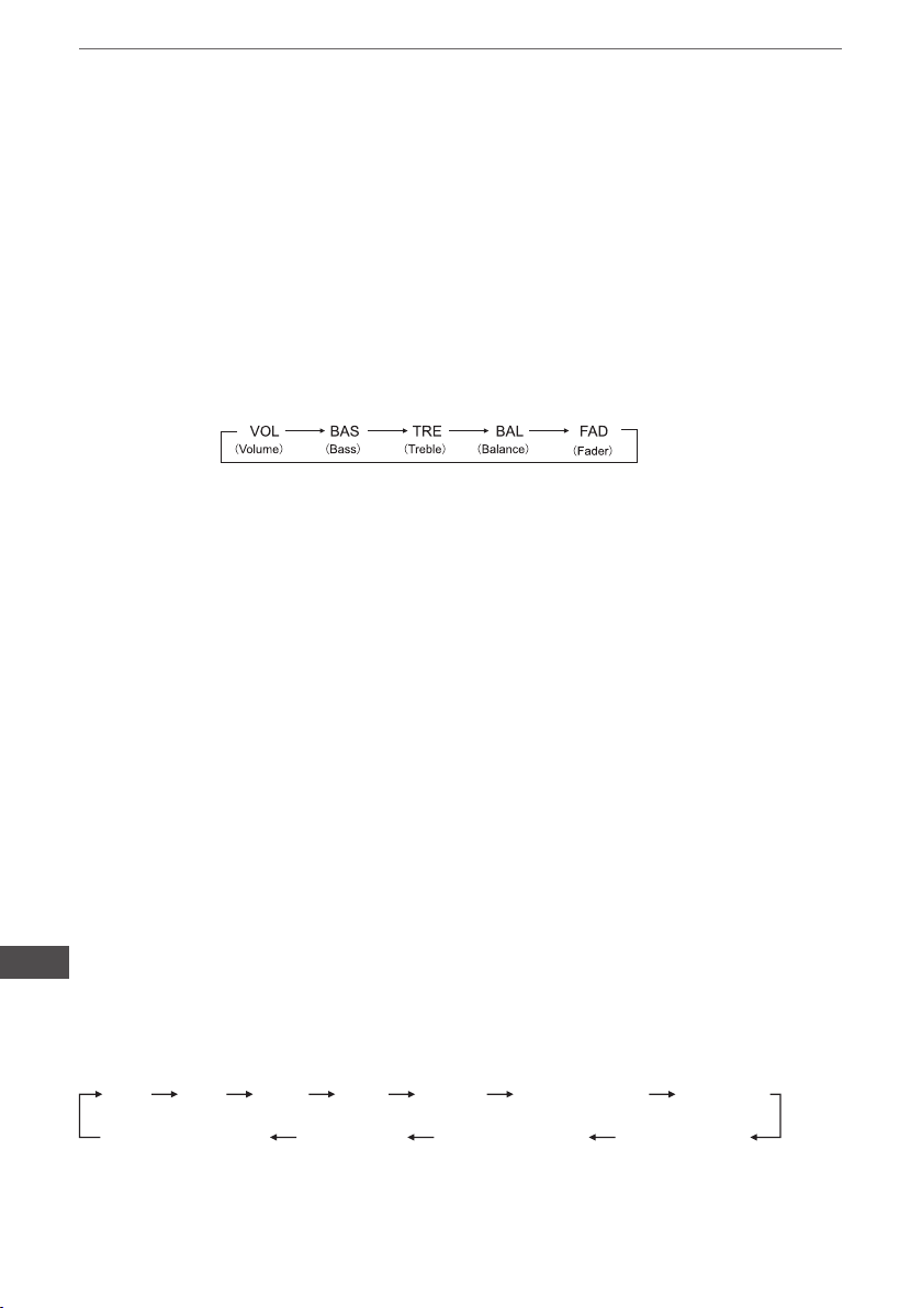
SOUND ADJUSTMENT
Turn on (3) can adjust the desired volume quality.
Press SEL button (3) will change in the following order.
Option:
VOLUME
Rotating this knob, you can adjust VOL/BASS/TREB/BAL/FAD . To select the functions, press
the VOL knob shortly until the desired functions are shown on the display.
Increase or decrease the volume by turn the VOL knob right or left. These buttons
can be used to adjust the BASS, TREBLE, BALANCE and FADER.
BASS
Press VOL/SEL button(3) one time. Adjust bass level by using VOL/SEL(3) Knob.
TREBLE
Press VOL/SEL button(3) two times. Adjust treble level by using VOL/SEL(3) Knob
BALANCE
Press VOL/SEL button(3) three times. Adjust sound balance between left and right speakers
by using VOL/SEL(3)Knob.
FADER (optional)
Press SEL button(3) four times. Adjust sound balance between front and rear speakers by using VOL/SEL(3) Knob.
EN
SELECT MENU
Press VOL/SEL button for several seconds, selecting menu is activated as cyclical
mode of following function for use’s selection:
VO L TR E
Press VOL/SEL button shortly and turn VOL button to right or left to select different
menu mode.
BA S
ST ER EO /M ON O DX /L OC MU TE O FF
8
BA L
FAD
SU B ON /O FF
DS P OF FLO UD O FF /O N

Owner’s manual
MUTE OFF/ON
Select “MUTE on ” mode to cut down the speakers output, return to “MUTE OFF”
mode to resume the speakers output.
LOC/DX SELECTOR
Press SEL buttom and choose LOC to select strong or weak station reception. It is set to
LOC mode when LOC is rst pressed. “LOC” appears and only local station is available. It is
switched to DX mode when LOC is pressed again. Both distance and local stations can be
received.
LOUDNESS ON/OFF
Press SEL button, and choose LOU to increase the low frequency. This can improve the sensitivity of your ears. And ” LOUD” appears in the LCD when the loudness mode is activated.
MO/ST SELECTOR
Press SEL button and select ST MONO or STEREO mode. When “ST”appears in the LCD
display. During the player mode, press the button to switch left speaker/right speaker/stereo.
AREA SETUP
In Radio mode‘ Press SEL button for several seconds, LCD will be show from AREAUSA/
EUR. At AREA USA/EUR. You can use VOL +/- to select the AREA frequency.
DISPLAY
Press DISP button (5) to operate as the conversion of each display mode as follow:
- Time is displayed for 5sec when DISP key is pressed, and it returns to its
previous display unless DISP key is pressed again.
3) From the clock mode, when DISP Key is pressed for longer than 1sec,
clock mode switches to clock Adjusting mode and the clock display
begins ashing. At this time clock or minute can be changed by pressing(+/-),
or the ENCODER VOLUME.
LIQUID CRYSTAL DISPLAY
Exhibit current frequency and activated functions on the display (6).
FLASHING LED
When ACC off ,take out the from panel from main unit that the LED (7) will be ashing.
EN
9
Owner’s manual
RESET
RESET button (8) is placed on the housing and must be activated with either
a ball point pen or thin metal object. (Do not use sharp object to avoid damaging
the unit.) The RESET button (8) is to be activated for the following reasons:
- Initial installation of the unit when all wiring is completed.
- All the function buttons do not operate.
- Error symbol on the display.
RADIO OPERATION
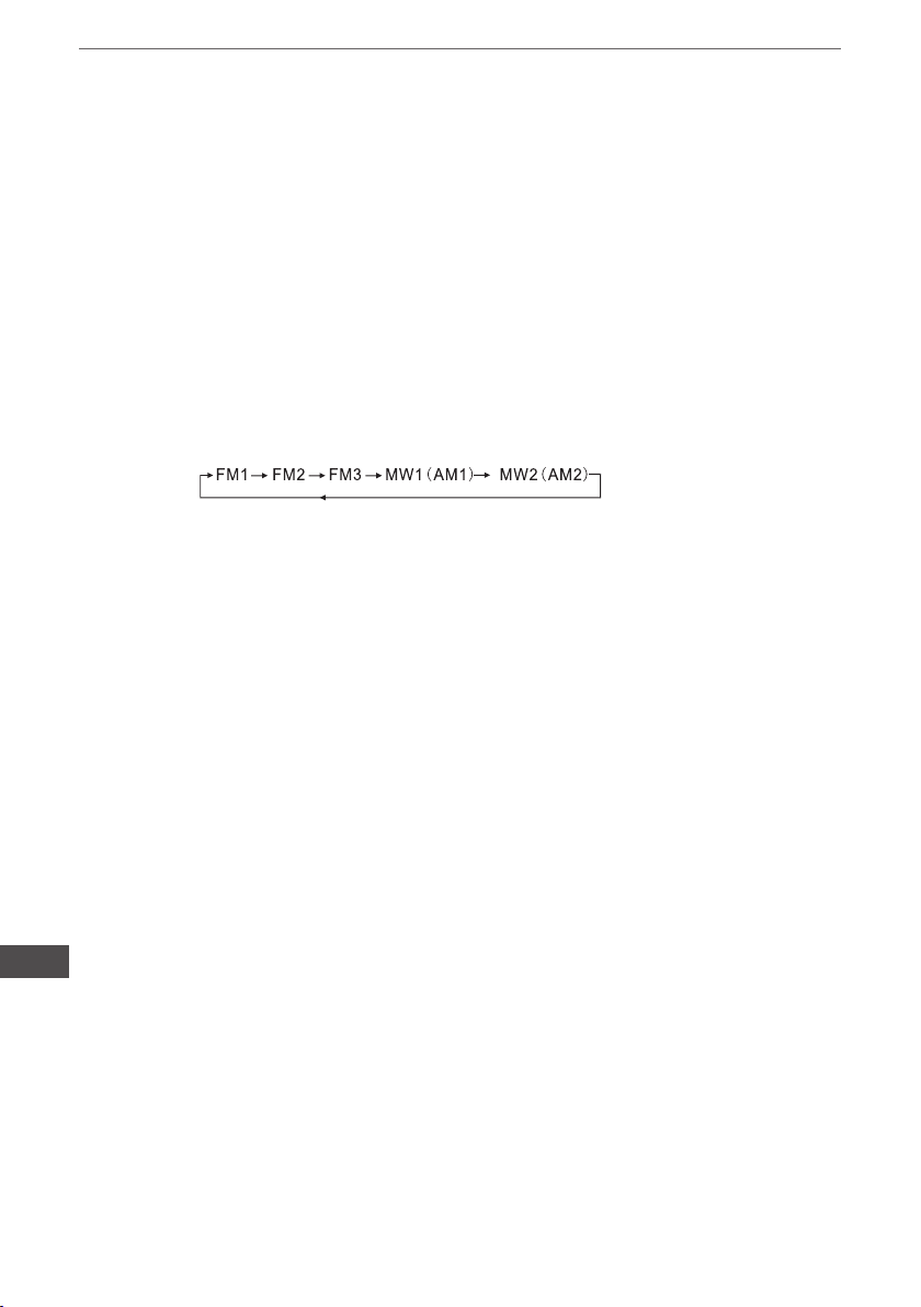
BAND SELECTION
At tuner mode, press BAND button (9) to select the desired band. The reception band will
change in the following order:
STATION SELECTION
Press TUNE/SEEK/TRACK FORWARD button (10) or TUNE/SEEK/TRACK
REVERSE button (11) shortly for manual tuning function.
Press for several seconds the automatic tuning mode (SEEK
mode) is selected.
AUTOMATICALLY MEMORY STORING & PROGRAM SCANNING
-Automatically Memory Storing
Press AMS(MP3) button (12) for several seconds, the radio searches from the current frequency and checks the signal strength until one cycle search is nished.
And then 6 strongest stations are stored into the corresponding preset number button,
- Program Scanning
Press AMS(MP3) button (12) shortly to scan preset station. When the AMS mode is carry out,
“INT” appear on LCD display, the unit scan each stored station for 5 seconds, you also can
press the corresponding number button or AMS button. Your desired station will start playing.
EN
STATION STORING
Press preset button (13~18)
1) RADIO MODE.
M1 ~ M6
- PRESET MEMORY is loaded when key is pressed for less than 1 second.
- PRESET MEMORY is saved when key is pressed for longer than 1 sec.
2) CD/MP3/FLASH MP3
PLAY/ PAUSE
Press preset button (13) is activated. During a PAUSE, DISC INDICATOR ashes.
TOP - First song will play when Top key is pressed for lunger than 0.5 sec during play.
10

Owner’s manual
INT
Press preset button (14) During INTRO ON, INT indicator comes on and begins playing the rst
10sec of each song, until the last song is played. It begins playing the entire track from where INT
started
RPT
Press preset button (15) Flash play mode: REPEAT ON / OFF is activated.
When REPEAT ON, RPT INDICATOR comes on and repeats the current music track.
RDM
Press preset button (16) During RANDOM ON, RDM INDICATOR is turned on and each track of
disc is played in random instead of normal order.
SELECT TRACKS
During USB/SD operation, press SEEK “<<” (11) button or SEEK ”>>”(10) button to move to the
previous track or the following track, Track number shows on display. During USB / SD, hold
SEEK “<<” (11) button or SEEK ”>>”(10) to fast reverse or fast forward. Music play starts from
when you release the button.
Press preset button (17 18)
- MP3 MODE : 10 TRACK UP / DOWN is activated.
When the total track is 10 or less, KEY is inactivated.
EN
11
Owner’s manual
RDS (RADIO DATA SYSTEM) OPERATlON
AF :Alternative Frequencies
~ Setting RDS Mode Press AF button (20) and release immediately to switch on or off RDS mode.
Whenever RDS is switched on, symbol “AF” appears on the display.
AF / REG
AF
- AF I REG key directs the activation of AF SEARCH.
- AF indicator is displayed when AF is ON, AF search is activated when reception is bad.
- During FM MODE, when AF is ON, SEEK, SCAN, AUTO, MEMORY function can only receive
and save RDS program. However, when Italy option is in use, regardless of RDS programs that
satisfy SD LEVEL Can be received and saved.
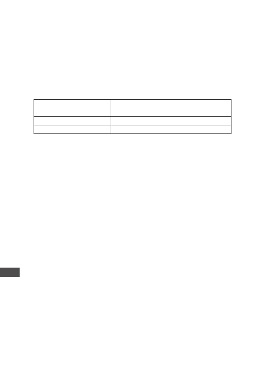
Indicator Condition
AF ON AF ON MODE, RDS information is received.
AF OFF AF OFF MODE
AF blink AF ON MODE, RDS information is not received.
REGION
- AF MODE is converted to REGION ON I OFF MODE when AF ON MODE 15 pressed for
longer lsec.
- ON : Pl CODE is checked when AF CHECK in progress
- OFF: PI CODE and COVERAGE AREA is not checked when AF CHECK in progress.
PTY
RADIO MODE
- Previous PTY is displayed when PTY key (16) is pressed. If there are no keys entered for
2 seconds, previously selected PTY is searched. During 1 LOOP, if desired PTY is not found, NO
PTY is displayed.
- 2 program types are SPEECH and MUSIC.
By pressing PTY once, MUSIC is entered. When PTY is pressed the second time, SPEECH is
entered.
M1~M6 keys can be used to select the desired program type.
TA
TA button (12) is operated as follows:
- TA is turned ON / OFF and TA indicator is displayed. When trafc announcement is transmitted,
regardless of the mode, trafc announcement is received.
If VOLUME LEVEL is below 20, VOLUME LEVEL is raised to 20, and returns to its previous
EN
mode and volume level when the trafc announcement is over.
If volume is adjusted during trafc announcement, only the previous volume is valid.
- When TA is on, SEEK, SCAN, AUTO MEMORY function can be received or saved only when
trafc program identication code has been received.
- When TA is ON, trafc program identication code is not received during specied time.
TAALARM : NO TA/ TP is displayed and alarm is set off.
TA SEEK : TA SEEK is activated.
12

Owner’s manual
BLUETOOTH
1.Pairing connect.
Turn on car unit, put your mobile near the unit, activate your mobile bluetooth function.Soon the
phone will nd the new bluetooth device “CAR AUDIO” . Input the pairing password “8888” and
clik OK. The phone will prompt the matching successful.When the pairing connect is successful,on
the LCD, it shows BT ON, and the bluetooth logo “ ”will stop blinking .Then you may perform the
bluetooth operation.
REMARK:depend on bluetooth mobile, the bluetooth system support “HSP” “HFP” “A2DP” and
AVRCP bluetooth prole.
2.Handsfree phone service
If your mobile phone have matched with the unit, you can dial calls out through your mobile
phone. It will turn to unit automatically when calling come in and the calling phone number will
indicate on the LCD screen.
-Press the “BAND” button shortly to accept the call .Then you can talk with the other party through
the mic on the panel.
-Press “MUTE” button shortly to reject the call when calling come in.
-Press “MUTE” button shortly to hang up after you nish the talk.
3.Advance Audio distributing prole(A2DP) playing.
Through mobile and unit A2DP connected, press “MODE” and turn to A2DP mode at the same
time, the music playing in mobile can turn to the unit audio system play. “A2DP” will display on
LCD.
-Press button “ <<” and “ >> ” in the panel can select the music track.
-Press “ PAUSE” button shortly to pause the music playing.
-Press “BAND”(mode) longly to temporarily discommect the bluetooth.
-Press “BAND”(mode) button longly again to reconnect the bluetooth.
4.Phone number book.
This bluetooth system can automatically store incoming call numbers, up to 10 phone numbers.
-Press “MUTE”(mode) button longly to enter the phone number book and press VOL button to
look up the phone number.
-Press “BAND” button once can call out you desired phone number.
5. Interrupt bluetooth connection/reconnection.
Pressing the “BAND” button shortly to interrupt the bluetooth connection when your are talking a
call and the voice can turn to mobile speaker.
Press “BAND” button again to reconnection.
NOTE:Different mobile phone have different responses.We do not guarantee all the
operation of connectable devices.
6. How to delete stored phone number?
The unit can store ten number of missed ,rejected and ANS separately, and the rst number will
auto deleted when the 11th number calling
7.How to use “RECEIVED” “MISSED” “REJECTED” MANU
ANS/AUTO ANS” Functions.
Press MUTE” for 3 seconds to enter into “RECEIVED” “MISSED” “REJECTED” MANU ANS/AUTO
ANS”. Turn VOL button for choosing the telephone number.
EN
13
Owner’s manual
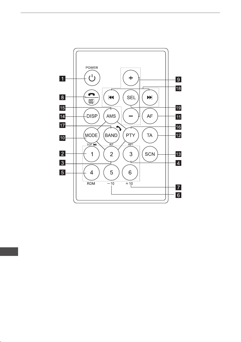
REMOTE CONTROL LAYOUT
EN
14
1. PowerButton
2. Pause / Play / Preset Button1
3. Intro / Preset Button2
4. Repeat Playing / Preset Button3
5. Random / Preset Button4
6. Preset Button5
7. Preset Button6
8. Mute / Hangup a call
9. Volume Control
10. Mode Switch
11. Alternative Frequencies Button
12. TrafcAnnouncement Button
13. Scan Button
14. Display Button
15. APS / AMS Button
16. Programe Type Button
17. Band Switch / Receive a call
18. Tuning / Selecting Tracks / F F / F R
19. Select Button
Owner’s manual
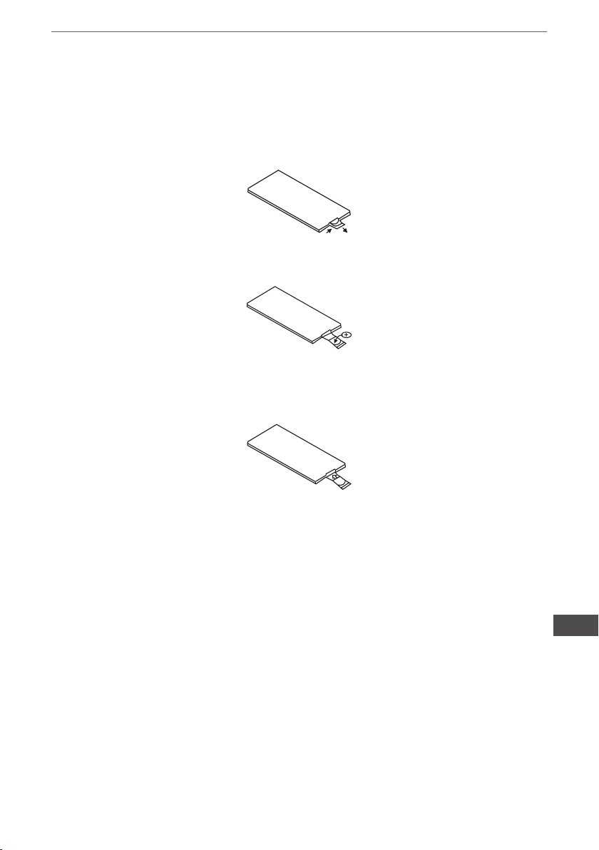
Replacing the Battery
When the operational range of the remote control becomes short or non functions while operating
Replace a new CR2025 battery Make sure the battery polarity before replacement
1. Pull out Battery Holder while pressing the stopper
2. Put the button type battery(+)mark upward into the Battery Holder
3. Insert the Battery Holder into the Remote control
EN
15

SPECIFICATION
General
Power Supply Requirements:
Load Impedance
Maximum Output Power:
Chassis Dimensions:
Current Drain:
Tone Controls
Bass (at 100Hz):
Treble (at 10K):
USB/SD MUSIC Player
Signal to Noise Ratio:
Channel Separation:
Frequency Response:
FM Radio
Frequency Coverage (MHz):
IF:
Sensitivity (S/N-30dB):
Stereo Separation:
Owner’s manual
DC 14,4V, Negative Ground
4 ohms
40W X 4(CH)
178x130x50mm(WxDxH)
15A
+10dB/-10dB
+10dB/-10dB
More than 60dB
More than 60dB
20Hz-20KHz
87 5 -108MHz
10.7MHz
12dBu
>30dB
AM Radio
Frequency Coverage (KHz):
IF:
Sensitivity (S/N-20dB):
Remarks
Specications subject to change without notice.
„The Lechpol company declares that product PY-9398 is consistent with the essential requirements and other relevant provisions
of directive 1999/5/EC. The proper declaration for download from www.lechpol.eu”
522 -1620KHz
450KHz
42dBu
EN
16

Bedienungsanleitung
INHALT
Instalation 18
Anschlussdiagramm 20
Frontplatte 21
Allgemeine Funktionen 22
Radio Funktionen 24
RDS Funktionen 26
Bluetooth Funktionen 27
Fernbedienung 28
Technische Daten 30
DE
17
Bedienungsanleitung
INSTALLATION
VORSICHTSMASSNAHMEN
Der Ort der Montage sollte so gewählt werden, dass das Gerät den Fahrer nicht stört.
Vor dem endgültigen Einbau, vorübergehend Gerät mit Spannung versorgen und sicherstellen,
dass es richtig angeschlossen ist und dass sowohl das Gerät als auch das System in normalen
Parameter funktionieren.
Verwenden Sie nur die mitgelieferten Teile zur korrekten Installation. Die Verwendung anderer
Bauteile kann zu Störungen oder Geräteschäden führen.
Fragen Sie Ihren nächstgelegenen Autohändler, wenn die Installation Bohrungen oder sonstige
Änderungen des Autos erfordert.
Installieren Sie das Gerät so, dass es nicht den Fahrer stört und die Passagiere nicht verletzt im
Falle eines plötzlichen Bremsmanövers, wie eine Not-Bremsung.
Installieren das Gerät nicht an Orten, wo es hohen Temperaturen, wie Sonnenlicht, warme Luft,
heiße Luft von der Heizung oder an Orten mit Staub, Schmutz oder starken Vibrationen ausgesetzt ist.
Schützen Sie das Gerät vor Feuchtigkeit.
FRONTMONTAGE (Methode A) Geräteeinbau
1. Armaturenbrett
2. Rahmen
Nach dem Einlegen in das
Armaturenbrett, wählen Sie die
Halter abhängig von der Dicke des
Armaturenbretts und biegen sie diese
um den Rahmen zu befestigen (Abb. 1)
3. Schraube
DE
18
 Loading...