


CAR POWER AMPLIFIER
PY-4C127
WZM0026
Bedienungsanleitung (1 - 8)
Owner’s manual (9 - 14)
Instrukcja obsługi (15 - 20)
Manual de utilizare (21 - 26)
DE
EN
PL
RO

Bedienungsanleitung
HINWEISE FÜR FUNKTIONEN UND BEDIENELEMENTE
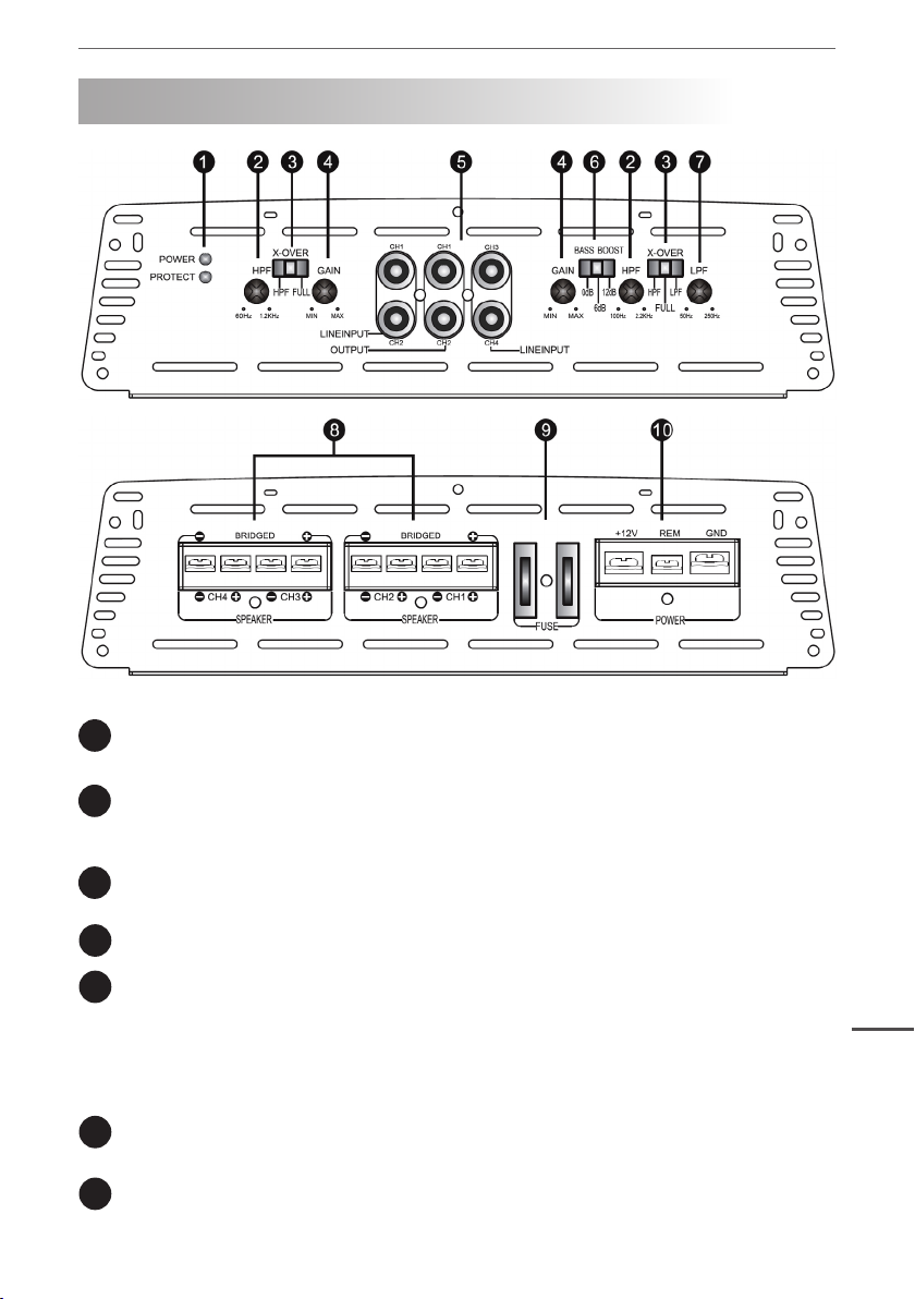
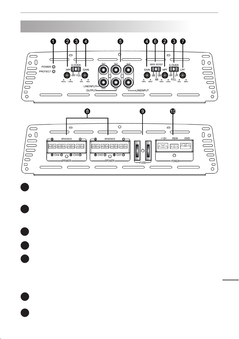
LED LEUCHTE
1
Grüne LED: der Verstärker ist Betriebsbereit; Rote LED: der Verstärker ist im Schutzmodus.
HPF
2
Regler für Hochpass Frequenzverteilung: Der Verstellbereich liegt zwischen 60Hz und
1.2KHz (CH1/CH2), Der Verstellbereich liegt zwischen 100Hz und 2.2KHz (CH3/CH4).
X-OVER
3
Optionale Regler für Hochpasslter (HPF)/ Vollpasslter (FULL)/ Niedrigpasslter (LPF).
PEGEL Lautstärkeregler.
4
NIEDRIGPEGEL EINGANG
5
Eingang des Verstärkers. Hier wird der Vor-Verstärkte Ausgang einer Quelle angeschlossen.
(CD Player, DAT, usw.).
NIEDRIGPEGEL AUSGANG
Durchgeschleifter Ausgang des Verstärkers. Hier wird ein anderer Verstärker mit einem
Niedrigpegel Eingang angeschlossen.
BASS BOOST
6
Optionaler Schalter für Bassverstärkung 0dB /6dB/12dB.
LPF
7
Regler für Niedrigpasslter (LPF). (Der Verstellbereich liegt zwischen 50Hz und 250Hz).
DE
3
Bedienungsanleitung
SPEAKER
8
Lautsprecher Anschlussklemmen.
SICHERUNG
9
Standard Sicherung, zum Austauschen bei durchgebrannter Sicherung nur denselben Typus
verwenden.
+12V
10
Anschlussklemmen für + 12 V Gleichstrom (Von der Autobatterie).
REM
Terminal zum Anschluss des Fernbedienungskabels, welches von der Quelle kommt und die
die Einschaltung des Verstärkers kontrolliert. Angelegte Spannung muss zwischen 10 und 15
V Gleichstrom sein.
GND
Masseanschluss. Wird an der Karoserie des Autos angeschlossen. Das Kabel sollte so kurz
wie möglich sein.
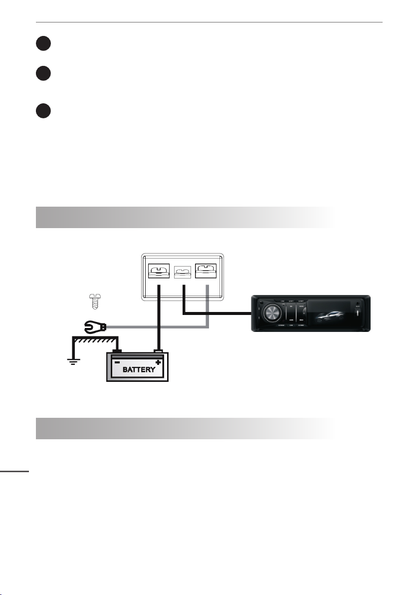
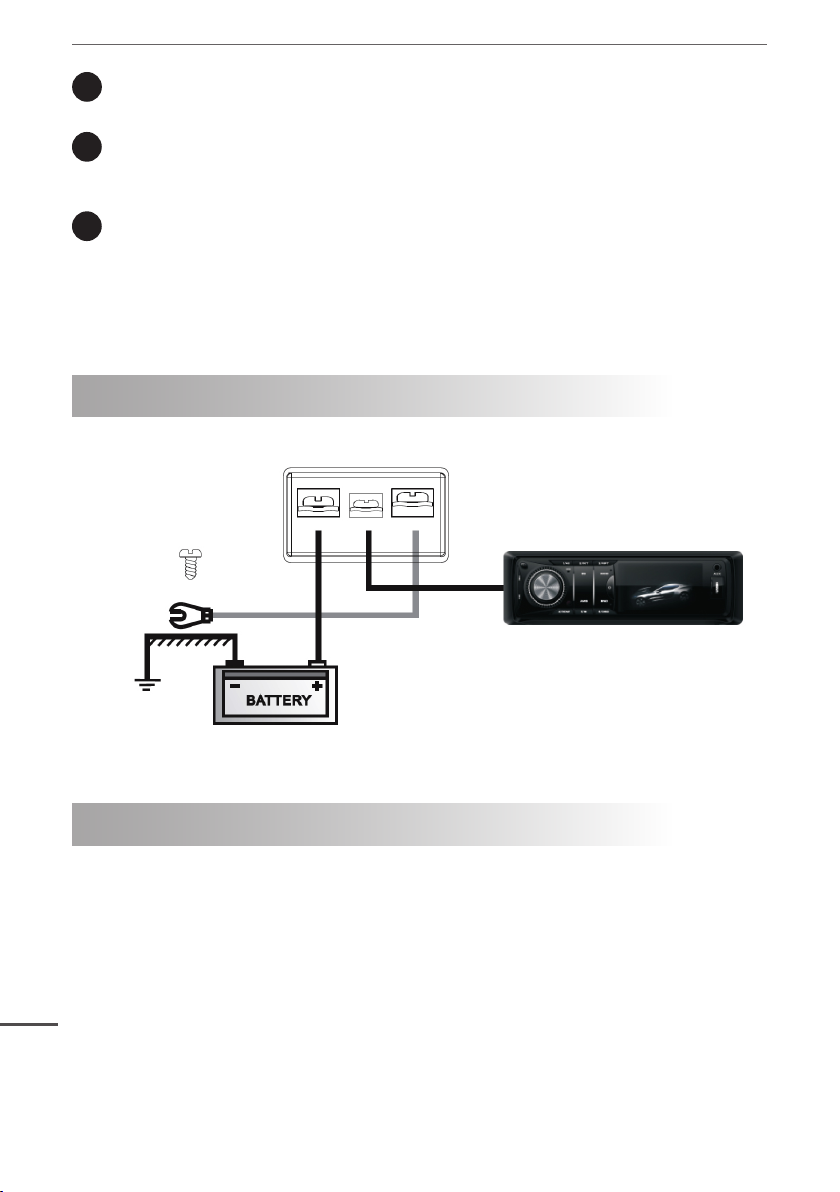
ELEKTRISCHE ANSCHLÜSSE
+12V REM GND
An die Fernbedienung der externen
Signalquelle anschließen.
An + 12V durch eine passende
An der Karoserie
des Fahrzeugs
anschließen.
Sicherung anschließen.
TECHNISCHE DATEN
Leistung RMS @ 14.4V DC
Leistung @ 4Ohm 80W x4
DE
Leistung @ 2Ohm 120W x4
Leistung in Brücke @ 4Ohm 200W x2
Minimale Impedanz des Lautsprechers 2ohm
Verzerrung THD 0.01%
Frequenzgang 20Hz ~ 20KHz
Eingangs-Sensibilität 0.2V ~ 6V
Eingangs-Impedanz 10K
Signal- Rauschabstand 98dB
Stereo Trennung 50dB
4
Bedienungsanleitung
Crossover network
Tiefpasslter 50Hz ~ 250Hz
Bass boost 0dB /6dB/12dB
Hochpasslter 60Hz-1.2KHz / 100Hz-2.2KHz
Sicherung 30A x2
Abmessungen (LxWxH) 360x240x64mm
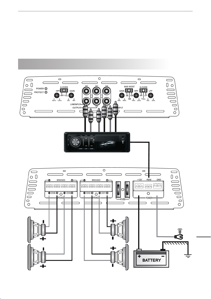
VERBINDUNGEN DES GERÄTES 4 KANAL STEREOMODUS
An die Fernbedienung
der externen
Signalquelle
anschließen.
Lautsprecherimpedanz 2~4Ohm
DE
An der
Karoserie des
Fahrzeugs
anschließen.
5
Bedienungsanleitung
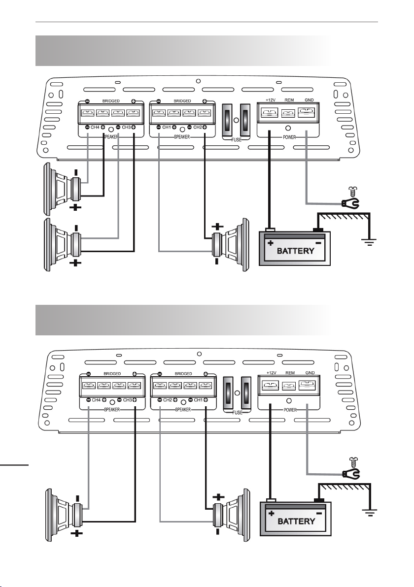
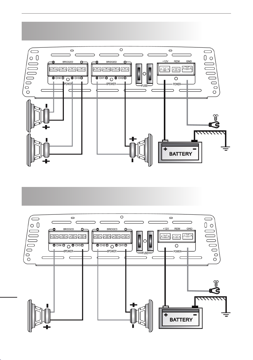
VERBINDUNGEN DES GERÄTES
3 KANAL BRÜCKENMODUS
Lautsprecherimpedanz 2~4Ohm Lautsprecherimpedanz 4~8Ohm
An der
Karoserie des
Fahrzeugs
anschließen.
DE
6
VERBINDUNGEN DES GERÄTES
3 KANAL BRÜCKENMODUS
Lautsprecherimpedanz 4~8Ohm
An der
Karoserie des
Fahrzeugs
anschließen.

Bedienungsanleitung
STÖRUNGSBEHEBUNG
Im falle einer Störung, sehen Sie in der nachstehenden Liste die möglichen Fehlerquellen und
ihre Behebung. Testen Sie immer die Lautsprecher und Kabel.
DER VERSTÄRKER LÄST SICH NICHT EINSCHALTEN
• Überprüfen Sie die Erdung.
• Überprüfen Sie die Spannungsversorgung von + 12V Gleichstrom; sie sollte mindestens + 10V
betragen.
• Überprüfen Sie die Spannung der Batterie.
• Überprüfen Sie alle Sicherungen
• Überprüfen Sie ob die Schutz - LED leuchtet. Wen Ja, dann Verstärker kurz ausschalten und
wieder einschalten.
DIE SCHUTZ–LED LEUCHTET BEIM EINSCHALTEN DES VERSTÄRKERS
• Überprüfen Sie die Anschlusskabel der Lautsprecher nach Kurzschlüssen.
• Die Lautstärkeregelung der Zentrale sollte auf Minimum sein.
• Lautsprecher entfernen und Verstärker neu starten. Wenn die LED noch immer leuchtet, kann
das Gerät defekt sein.
• Der Verstärker schaltet sich automatisch ab bei Überhitzung über 85ºC, Dadurch wird das Gerät
vor Beschädigung bewahrt.
DER VERSTÄRKER WIRD ZU HEISS
• Überprüfen Sie ob die Lautsprecherimpedanz für dieses Gerät korrekt ist.
• Überprüfen Sie die Anschlusskabel sowie die Lautsprecher nach Kurzschlüssen.
• Überprüfen Sie die Luftzirkulation in der nähe des Geräts. In einigen Fällen ist ein Ventilator
notwendig.
VERZERRTER KLANG
• Überprüfen Sie die Verstärkung des Signals.
• Überprüfen Sie die korrekte Einstellung der Filter.
• Überprüfen Sie die Anschlusskabel der Lautsprecher nach Kurzschlüssen.
LAUTES RAUSCHEN IN DEN LAUTSPRECHERN
• Die Ursache ist ein schwacher Massenkontakt der Verbindungskabel.
WARNUNG
1. Lautstärke über den zugelassenen Werten kann die Lautsprecher beschädigen.
2. Vorschicht bei Benutzung des Verstärkers in der nähe des Benzintanks und elektrischen
Leitungen.
3. Schützen Sie die Kabelverbindungen, um mögliche Schäden an Kabeln oder Kurzschlüsse
zu vermeiden.
4. Die Stormversorgung muss unbedingt von der Anode durch eine Sicherung erfolgen.
5. Beim Austausch der Sicherung stellen Sie sicher dass es derselbe Typ ist.
Specications are subject to change without notice.
DE
7
Bedienungsanleitung
DE
8
Owner’s manual
INSTRUCTIONS FOR FUNCTIONS AND CONTROLS
INDICATOR LIGHT
1
When this LED sends out green light, it means that this amplier have being working now.
When this LED sends out red light, it means that the self-protection of the amplier.
HPF
2
High pass frequency adjusting knob, the frequency ranges from CH1/CH2 60Hz to 1.2KHz,
CH3/CH4 100Hz to 2.2KHz.
X-OVER
3
Optional switches for high pass lter (HPF)/full pass lter (FULL)/low pass lter (LPF).
GAIN Knob for volume adjustment.
4
LOW LEVEL OUTPUT
5
A daisy chain output for connection to another amplier with a low level input using only a
single RCA output from the source(head unit)
LOW LEVEL INPUT
For connection to any source (head unit) with a low level output. This is your RCA output
from the source (head unit).
BASS BOOST
6
The boost ranges from 0dB /6dB/12dB.
LPF
7
Low pass frequency adjusting knob, the frequency ranges from 50Hz to 250Hz.
EN
9

Owner’s manual
SPEAKER
8
Speaker connecting terminals.
FUSE
9
Standard automatic fuse, you must use the same power fuse if you need to change it.
+12V
10
Anode of power connection terminals. Connect to the anode of car battery.
REM
Terminal to be connected with remote cable, which comes from the source and which controls the amplier switching on. Applied voltage must be between 10 and 15 VDC.
GND
Ground terminal. Connect to the car chassis. Keep the length of the ground cable to a minimum.
ELECTRICAL CONNECTION
+12V REM GND
Connect to remote turn-on lead of
source unit.
Connect to +12v of battery with
Connect to chassis
ground of vehicle.
appropriate fuse VALUE.
SPECIFICATION
RMS power @ 14.4V DC
Power @ 4ohms 80W x4
Power @ 2ohms 120W x4
Bridged Power @ 4ohms 200W x2
Minimum speaker impedance 2ohm
THD distortion 0.01%
EN
Frequency response 20Hz ~ 20KHz
Input sensitivity 0.2V ~ 6V
Input impedance 10K
Signal to noise ratio 98dB
Channel separation 50dB
10

Owner’s manual
Crossover network
Low pass lter 50Hz ~ 250Hz
Bass boost 0dB /6dB/12dB
High pass lter 60Hz-1.2KHz / 100Hz-2.2KHz
Fuse rating 30A x2
Size (LxWxH) 360x240x64mm
SYSTEM WIRING - 4 CHANNEL STEREO CONFIGURATION
Connect to remote
turn-on lead of source
unit.
Speaker impedance 2~4ohm
EN
Connect
to chassis
ground of
vehicle.
11
Owner’s manual
SYSTEM WIRING
3 CHANNEL BRIDGED MODE CONFIGURATION
Speaker impedance 2~4ohm Speaker impedance 4~8ohm
Connect
to chassis
ground of
vehicle.
EN
12
SYSTEM WIRING
2 CHANNEL BRIDGED MODE CONFIGURATION
Speaker impedance 4~8ohm
Connect
to chassis
ground of
vehicle.

Owner’s manual
TROUBLESHOOTING
Before removing your amplier, refer to the list below and follow the suggested procedures.
Always test the speakers and their wires rst.
AMPLIFIER WILL NOT POWER UP.
• Check for good ground connection.
• Check that remote DC terminal has at least 10V DC.
• Check that there is battery power on the + terminal.
• Check all FUSES.
• Check that Protection LED is not lit. If it is lit, shut off amplier briey and then repower it.
PROTECTION LED COMES ON WHEN THE AMPLIFIER IS POWERED UP.
• Check for shorts on speaker leads.
• Check that volume control on the head unit is turned down low.
• Remove speaker leads, and reset the amplier. If the Protection LED still comes on, then the
amplier is faulty.
• The amplier will shut down automatically when the units‘ temperature goes up to 85°C, this will
protect the units from damage.
AMPLIFIER’S GETS VERY HOT.
• Check that the minimum speaker impedance for that model is correct.
• Check for speaker shorts.
• Check that there is good airow around the amplier. In some applications, an external cooling
fan may be required.
DISTORTED SOUND.
• Check that the level control’s is set to match the signal level of the head unit.
• Check that all crossover frequencies have been properly set.
• Check for shorts on the speaker leads.
HIGH SQUEAL NOISE FROM SPEAKERS.
• This is always caused by a poorly grounded RCA patch cord.
WARNING
1. Over high volume will damage your speakers.
2. Be cautious when you use the amplier near gasoline tank and electric wires.
3. Protect the connecting wires and parts to avoid any damage or short circuit.
4. The power must belee from the anode of the battery via FUSE.
5. Be sure that you use the same type of FUSE when you need to replace it.
Specications are subject to change without notice.
EN
13

Owner’s manual
EN
14

FUNKCJE I POŁĄCZENIA
Instrukcja obsługi
WSKAŹNIKI LED
1
Zielona dioda LED oznacza prawidłową pracę wzmacniacza. Czerwona dioda oznacza włączenie zabezpieczenia wzmacniacza.
HPF
2
Pokrętło regulacji górnego pasma częstotliwości w zakresie od 60Hz ~ 1.2KHz dla CH1/CH2
oraz od 100Hz do 2.2KHz dla CH3/CH4.
X-OVER
3
Przełącznik ltra górnego pasma (HPF)/całego pasma (FULL)/dolnego pasma (LPF).
GAIN Regulacja głośności.
4
LOW LEVEL OUTPUT
5
Gniazda wyjściowe audio niskiego poziomu. Służą do podłączenia innego wzmacniacza.
LOW LEVEL INPUT
Do podłączenia dowolnego źródła (radioodtwarzacz) z niskim poziomem wyjściowym.
BASS BOOST
6
Przełącznik podbicia basu 0dB /6dB/12dB.
LPF
7
Pokrętło regulacji dolnego pasma częstotliwości w zakresie od 50hz do 250Hz.
PL
15
Instrukcja obsługi
SPEAKER
8
Podłączenie głośników.
FUSE
9
Bezpiecznik. W przypadku konieczności wymiany, należy użyć bezpiecznika o tej samej wartości.
+12V
10
Podłączenie do + w akumulatorze.
REM
Gniazdo do podłączenia sterowania wzmacniaczem (włączenie/wyłączenie). Napięcie sygnału sterującego musi zawierać się w przedziale od 10 do 15V DC.
GND
Podłączenie uziemienia (jak najkrótszym kablem).
PODŁĄCZENIE ZASILANIA
+12V REM GND
Należy podłączyć do zdalnego
sterowania, które będzie sterowało
włączaniem i wyłączaniem
wzmacniacza.
Należy podłączyć do dodatniego
bieguna akumulatora +12V,
Podłączenie
uziemienia.
zapezpieczając odpowiednim
bezpiecznikiem.
SPECYFIKACJA
Moc RMS @ 14.4V DC
Moc @ 4ohm 80W x4
Moc @ 2ohm 120W x4
Moc - mostek @ 4ohm 200W x2
Minimalna impedancja głośnika 2ohm
Zniekształcenie THD 0.01%
Pasmo przenoszenia 20Hz ~ 20KHz
Czułość na wejściu 0.2V ~ 6V
PL
Impedancja wejściowa 10K
Stosunek sygnału do szumu 98dB
Separacja kanałów 50dB
16

Instrukcja obsługi
Regulacja
Filtr dolnego pasma 50Hz ~ 250Hz
Podbicie basu 0dB /6dB /12dB
Filtr górnego pasma 60Hz-1.2KHz / 100Hz-2.2KHz
Bezpiecznik 30A x2
Wymiary (DxSxW) 360x240x64mm
SCHEMAT PODŁĄCZENIA - 4 KANAŁY STEREO
Sterowanie
włączeniem /
wyłączeniem
wzmacniacza.
Impedancja głośników 2~4ohm
PL
Podłączenie
uziemienia.
17

Instrukcja obsługi
SCHEMAT PODŁĄCZENIA
3 KANAŁY W TRYBIE MOSTKA
Impedancja głośników 2~4ohm Impedancja głośników 4~8ohm
Podłączenie
uziemienia.
PL
SYSTEM WIRING
2 KANAŁY W TRYBIE MOSTKA
Impedancja głośników 4~8ohm
18
Podłączenie
uziemienia.

Instrukcja obsługi
ROZWIĄZYWANIE PROBLEMÓW
W pierwszej kolejności zawsze należy sprawdzić głośniki i ich połączenia.
WZMACNIACZ SIĘ NIE WŁĄCZA
• Należy sprawdzić podłączenie uziemienia.
• Należy sprawdzić czy sygnał sterujący wzmacniaczem ma napięcie przynajmniej 10V DC.
• Należy sprawdzić podłączenie zasilania do akumulatora.
• Należy sprawdzić bezpiecznik.
• Jeżeli na wzmacniaczu świeci się dioda zabezpieczenia, należy go wyłączyć i włączyć ponow-
nie.
DIODA ZABEZPIECZENIA ZAPALA SIĘ GDY WZMACNIACZ JEST WŁĄCZONY
• Należy się upewnić, że nie ma zwarcia na kablach głośnikowych.
• Należy spróbować zmniejszyć poziom dźwięku.
• Należy wyłączyć wzmacniacz i odłączyć kable głośnikowe i sygnałowe. Jeżeli po włączeniu
wzmacniacza bez podpiętych kabli dioda dalej się zapala - oznacza to uszkodzenie wzmacniacza.
• Jeżeli temperatura wzmacniacza przekroczy 85°C, wzmacniacz automatycznie się wyłączy (za-
bezpieczenie przed przegrzaniem).
WZMACNIACZ MOCNO SIĘ NAGRZEWA
• Należy sprawdzić czy podłączone głośniki mają odpowiednią impedancję.
• Należy się upewnić, że nie ma zwarcia na kablach głośnikowych.
• Należy sprawdzić czy wzmacniacz ma odpowiednią wentylację. W niektórych przypadkach może
być konieczne zastosowanie dodatkowego chłodzenia.
ZNIEKSZTAŁCONY DŹWIĘK
• Należy sprawdzić czy ustawiony jest odpowiedni poziom dźwięku w stosunku do poziomu z
urządzenia podłączonego do wzmacniacza.
• Należy sprawdzić czy pokrętła częstotliwości są poprawnie ustawione.
• Należy się upewnić, że nie ma zwarcia na kablach głośnikowych.
PISZCZĄCE ODGŁOSY Z GŁOŚNIKÓW
• Przyczyną jest zawsze brak masy na kablach RCA.
UWAGA
1. Zbyt głośny poziom dźwięku może uszkodzić głośniki.
2. Należy zachować szczególną ostrożność, gdy wzmacniacz znajduje się blisko baku paliwa
lub przewodów elektrycznych.
3. Należy zabezpieczyć przewody przed uszkodzeniami, uszkodzenie przewodu może spowodować zwarcie.
4. Przewód zasilający wzmacniacz musi być poprzedzony bezpiecznikiem.
5. Przy wymianie bezpiecznika, należy użyć bezpiecznika tego samego typu i o tej samej wartości.
Specykacja urządzenia może ulec zmianie bez powiadomienia.
PL
19

Instrukcja obsługi
PL
20

FUNCTII SI COMENZI
Manual de utilizare
INDICATOR LUMINA
1
Cand acest LED emite culoare verde, inseamna ca amplicatorul este in functiune. Cand
LED-ul emite culoare rosie, inseamna ca amplicatorul a intrat in regim de protectie.
HPF
2
HPF Buton reglare frecventa inalta: interval de reglaj intre 60Hz si 1.2KHz (CH1/CH2), interval de reglaj intre 100Hz si 2.2KHz (CH3/CH4).
X-OVER
3
Comutatoare optionale pentru ltre semnal: inalta (HPF), trece-banda (FULL) si joasa (LPF).
CASTIG Buton pentru reglarea volumului.
4
LOW LEVEL OUTPUT
5
Iesire pentru conectarea la un alt amplicator cu intrare low level folosind doar o singura
iesire RCA de la sursa (unitatea centrala).
LOW LEVEL INPUT
Intrare pentru conectarea la orice sursa (unitate centrala) cu iesire low level. Aceasta este
iesirea RCA de la sursa (unitatea centrala).
BASS BOOST
6
Comutatoare optionale pentru 0dB /6dB/12dB.
LPF
7
Buton reglare frecventa joasa (interval de reglaj intre 50Hz si 250Hz).
RO
21

Manual de utilizare
SPEAKER
8
Terminale de conectare a difuzorului.
FUSE
9
Siguranta standard, va trebui sa folositi o siguranta de acelasi tip in cazul in care doriti sa o
inlocuiti.
+12V
10
Anodul terminalelor de conectare. Conectati la borna “ + “ a bateriei de masina.
REM
Terminalul care controleaza pornirea amplicatorului. Tensiunea aplicata trebuie sa e intre
+10 si +15V DC.
GND
Terminal de masa. Conectati la sasiul caroseriei. Pastrati lungimea cablului de conectare la
masa cat mai scurt posibil.
CONEXIUNE ELECTRICA
+12V REM GND
Conectati la alimentarea sursei de
semnal.
Conectati la + 12V, printr-o siguranta
Conectati la
alimentarea sursei
de semnal .
adecvata.
SPECIFICATII
Putere RMS @ 14.4V DC
Putere @ 4ohmi 80W x4
Putere @ 2ohmi 120W x4
Putere in punte @ 4ohmi 200W x2
Impedanta minima difuzor 2ohm
Distorsiune THD 0.01%
Raspuns in frecventa 20Hz ~ 20KHz
Sensibilitate intrare 0.2V ~ 6V
Impedanta intrare 10K
Raport Semnal/Zgomot 98dB
RO
Separare canale 50dB
22

Manual de utilizare
Crossover network
Filtru trecere frecvente joase 50Hz ~ 250Hz
Bass boost 0dB /6dB/12dB
Filtru trecere frecvente inalte 60Hz-1.2KHz / 100Hz-2.2KHz
Siguranta 30A x2
Dimensiuni (LxWxH) 360x240x64mm
CONEXIUNI POSIBILE ALE SISTEMULUI
CONEXIUNE STEREO
Conectati la
alimentarea sursei de
semnal.
Impedanta difuzor 2~4ohmi
Conectati
la sasiul
masinii.
RO
23

Manual de utilizare
CONEXIUNE IN PUNTE 3 CANALE
Impedanta difuzor 2~4ohmi Impedanta difuzor 4~8ohmi
Conectati la
sasiul masinii.
RO
24
CONEXIUNE IN PUNTE 2 CANALE
Conectati la
sasiul masinii.
Impedanta difuzor 4~8ohmi

Manual de utilizare
DEPANARE
In cazul aparitiei unei anomalii de functionare, consultati lista de mai jos si urmati procedurile
sugerate. Vericati intotdeauna difuzoarele si cablurile acestora.
AMPLIFICATORUL NU PORNESTE
• Vericati conectarea la masa.
• Vericati ca terminalul de alimentare +12V DC sa aiba cel putin 10V DC.
• Vericati ca terminalul + al bateriei masinii sa aiba sucienta tensiune.
• Vericati toate SIGURANTELE.
• Vericati ca LED-ul de protectie sa nu e aprins. Daca este aprins, opriti scurt amplicatorul
si porniti-l din nou.
LED-ul DE PROTECTIE SE APRINDE CAND AMPLIFICATORUL PORNESTE
• Vericati sa nu existe scurtcircuite la conductorul de cablu al difuzorului.
• Fiti atenti ca volumul unitatii centrale sa e minim.
• Deconectati difuzorul si resetati amplicatorul. Daca LED-ul inca se aprinde, amplicatorul ar
putea sa e defect.
• Amplicatorul se va opri automat cand temperatura dispozitivului atinge 85ºC, acest lucru va
proteja dispozitivul de deteriorare.
AMPLIFICATORUL SE SUPRAINCALZESTE
• Vericati ca impedanta minima a difuzorului pentru modelul respectiv sa e corecta.
• Vericati sa nu existe scurtcircuite la nivelul difuzorului.
• Vericati curentul de aer din jurul amplicatorului. In unele cazuri, ar putea nevoie de un
ventilator.
SUNET DISTORSIONAT
• Vericati astfel incat controlul nivelului sa e setat astfel incat sa se potriveasca cu nivelul
semnalului unitatii centrale.
• Vericati ca ltrele de semnal sa e corespunzator setate.
• Vericati sa nu existe scurtcircuite la nivelul relor de la difuzor.
ZGOMOT PUTERNIC IN DIFUZOARE
• Acest lucru este provocat de o pamantare slaba (conectare la masa) a cablului de conexiune
RCA.
AVERTISMENT
1.Volumul peste limita admisa poate defecta difuzoarele.
2.Fiti precauti cand utilizati amplicatorul in apropierea rezervorului de benzina si a cablurilor
electrice.
3.Protejati cablurile de conectare si partile acestora pentru a evita orice deteriorare a cablurilor
sau aparitia unui scurtcircuit.
4.Alimentarea sistemului trebuie facuta obligatoriu prin SIGURANTA.
5.Asigurati-va ca folositi o siguranta de acelasi tip cu cea originala cand e nevoie sa o inlocuiti.
Specicatiile sunt supuse schimbarilor fara noticare prealabila.
RO
25

Manual de utilizare
RO
26


www.peiying.pl
 Loading...