

peerless-AV SmartMount ST632P, SmartMount ST632P-S, SmartMount SWV220/BK, SmartMount ST632, SmartMount ST632-S Installation And Assembly Manual
...Page 1
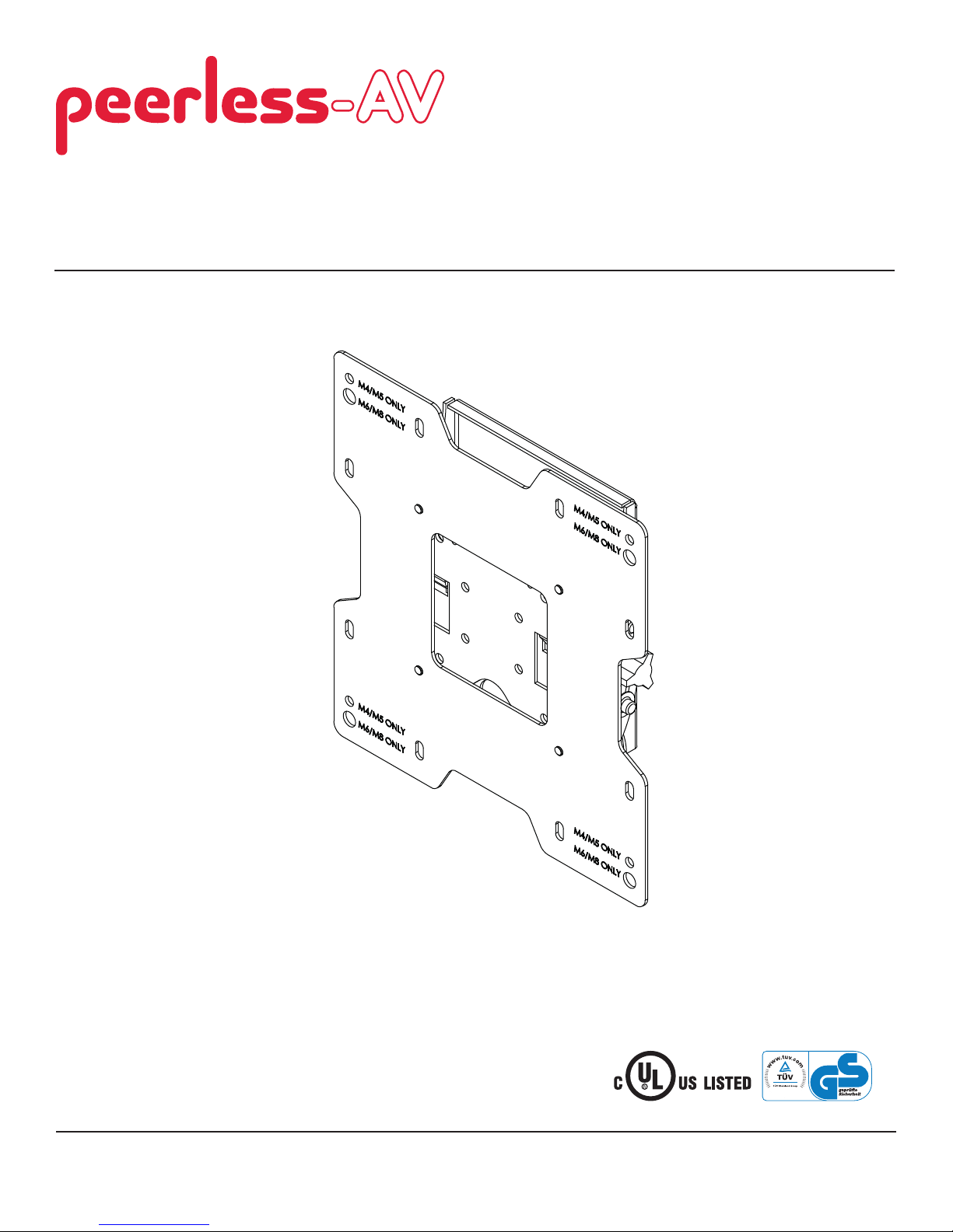
Installation and Assembly:
SmartMount™ Universal Tilt Wall Mount for 22" - 40"
(56 - 102 cm) Flat Panel Displays
Models: ST632P, ST632P-S, ST632, ST632-S, SWV220/BK, SWV220/SI
Features:
• Fits 22" - 40" fl at panel displays
• Effortless positioning and adjustment of the display
• Integrated security features provide effective theft
deterrence
2300 White Oak Circle • Aurora, Il 60502 • (800) 865-2112 • Fax: (800) 359-6500 • www.peerlessmounts.com
I
D
2
:
6
0
7
0
8
0
1
0
0
Max UL Load Capacity: 115 lb (52.2 kg)
ISSUED: 05-11-05 SHEET #: 201-9476-11 08-05-11
Page 2
NOTE: Read entire instruction sheet before you start installation and assembly.
WARNING
• Do not begin to install your Peerless product until you have read and understood the instructions and warnings
contained in this Installation Sheet. If you have any questions regarding any of the instructions or warnings, for US
customers please call Peerless customer care at 1-800-865-2112, for all international customers, please contact
your local distributor.
• This product should only be installed by someone of good mechanical aptitude, has experience with basic building
construction, and fully understands these instructions.
• Make sure that the supporting surface will safely support the combined load of the equipment and all attached
hardware and components.
• Never exceed the Maximum Load Capacity. See page one.
• If mounting to wood wall studs, make sure that mounting screws are anchored into the center of the studs. Use of
an "edge to edge" stud fi nder is highly recommended.
• Always use an assistant or mechanical lifting equipment to safely lift and position equipment.
• Tighten screws fi rmly, but do not overtighten. Overtightening can damage the items, greatly reducing their holding
power.
• This product is intended for indoor use only. Use of this product outdoors could lead to product failure and personal
injury.
• This product was designed to be installed on the following wall construction only;
WALL CONSTRUCTION HARDWARE REQUIRED
• Wood Stud Included
• Wood Beam Included
• Solid Concrete Included
• Cinder Block Included
• Metal Stud Do not attach except with Peerless Metal Stud Accessory Kit - ACC215;
(not evaluated by UL)
• Brick Contact Qualifi ed Professional (not evaluated by UL)
• Other or unsure? Contact Qualifi ed Professional (not evaluated by UL)
Tools Needed for Assembly
• stud fi nder ("edge to edge" stud fi nder is recommended)
• phillips screwdriver
• drill
• 5/16" (8 mm) bit for concrete and cinder block wall
• 5/32" (4 mm) bit for wood stud wall
• level
Table of Contents
Parts List.................................................................................................................................................................................3
Installation to Single Wood Stud Wall .....................................................................................................................................4
Installation to Solid Concrete or Cinder Block ........................................................................................................................5
Attaching Adapter Plate to Display with VESA 200 or 200 x 100 Mounting Pattern ...............................................................6
Attaching Hook Bracket to Display with VESA 75 or 100 Mounting Pattern ...........................................................................7
Installing and Removing Flat Panel Display ...........................................................................................................................8
2 of 34
ISSUED: 05-11-05 SHEET #: 201-9476-11 08-05-11
Page 3
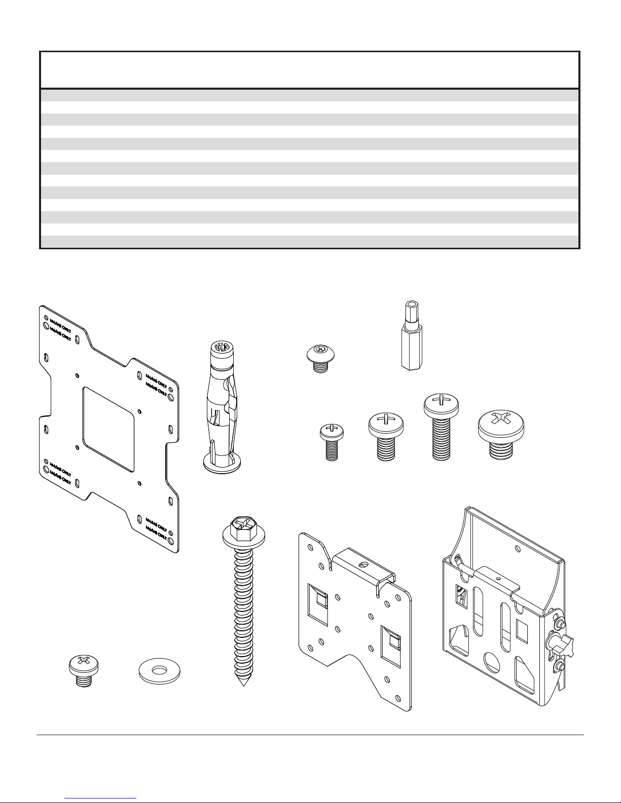
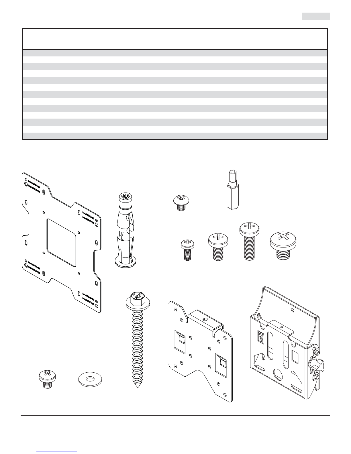
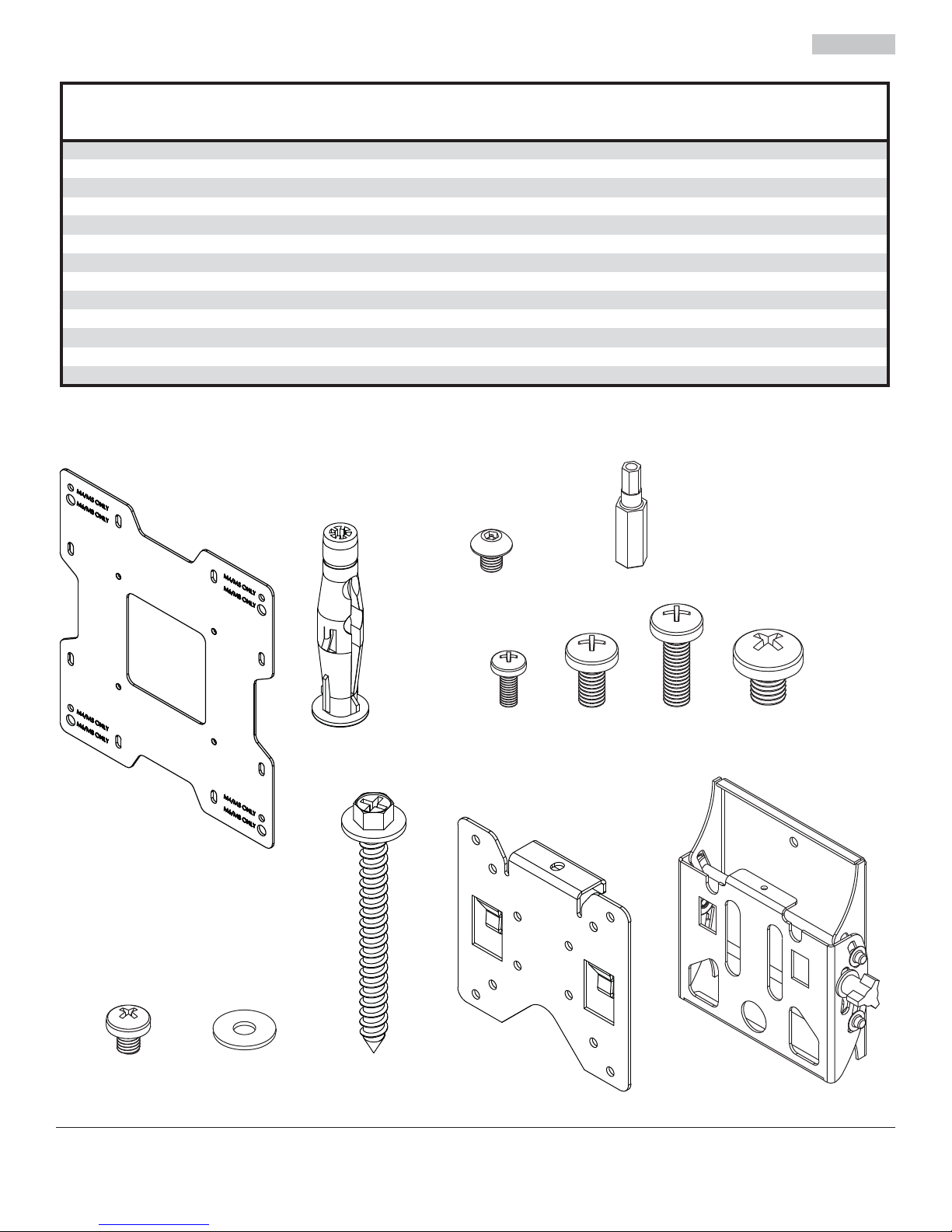
Before you begin, make sure all parts shown are included with your product.
Parts List
Description Qty Part #
A hook bracket 1 095-1346
B tilt assembly 1
C adapter plate 1 095-P1721 095-4721
D concrete anchor 2
E M4 x 10 mm phillips screw 4 504-9012 504-9012 504-9012 504-9012
F M6 x 12 mm phillips screw 4 520-1128 520-1128 520-1128 520-1128
G M6 x 20 mm phillips screw 4 520-9402 520-9402 520-9402 520-9402
H M8 x 10 mm phillips screw 4 520-1605 520-1605 520-1605 520-1605
I M5 x 6 mm phillips screw 5 520-1023 520-1023 520-1023 520-1023
J #10 washer 4 540-9400 540-9400 540-9400 540-9400
K #14 x 2.5" hex head wood screw 2 5S1-015-C03
L M5 x 6 mm socket pin screw 1 - - 520-1114 520-1114
M 4 mm securtiy driver 1 - - 560-1133 560-1133
Parts may appear slightly different than illustrated.
SWV220/BK SWV220/SI
ST632P,
095-0359
590-0320
ST632P-S,
Part #
095-4346
095-0360
590-0320
5S1-015-C03
ST632
Part #
095-1346
095-0359
095-P1721 095-4721
590-0320
5S1-015-C03
ST632-S
Part #
095-4346
095-0360
590-0320
5S1-015-C03
C
L
M
FG HE
D
I
J
K
3 of 34
A
B
ISSUED: 05-11-05 SHEET #: 201-9476-11 08-05-11
Page 4
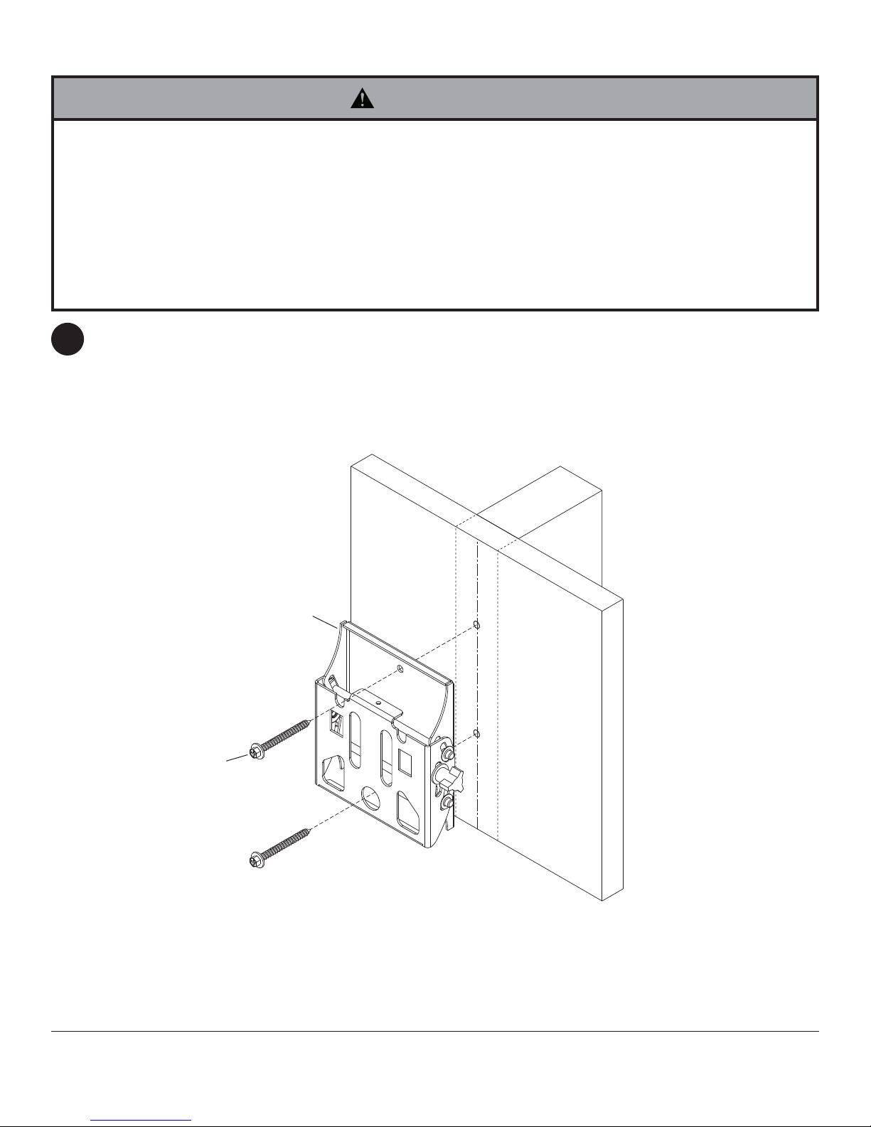
Installation to Single Wood Stud Wall
WARNING
• Installer must verify that the supporting surface will safely support the combined load of the equipment and all
attached hardware and components.
• Tighten wood screws so that wall plate is fi rmly attached, but do not overtighten. Overtightening can damage the
screws, greatly reducing their holding power.
• Never tighten in excess of 80 in. • lb (9 N.M.).
• Make sure that mounting screws are anchored into the center of the stud. The use of an "edge to edge" stud fi nder
is highly recommended.
• Hardware provided is for attachment of mount through standard thickness drywall or plaster into wood studs.
Installers are responsible to provide hardware for other types of mounting situations (not evaluated by UL).
Use a stud fi nder to locate the edges of the stud. Use of an edge-to-edge stud fi nder is highly recommended.
1
Based on its edges, draw a vertical line down the stud’s center. Place tilt assembly (B) on wall as a template,
making sure that the two mounting holes are over the stud centerline. Level tilt assembly, and mark the center of
the two holes. Drill two 5/32" (4 mm) dia. holes 2.5" (64 mm) deep. Make sure that the tilt assembly is level, secure
it using two #14 x 2.5" wood screws (K) as shown.
Skip to step 2.
K
B
4 of 34
ISSUED: 05-11-05 SHEET #: 201-9476-11 08-05-11
Page 5
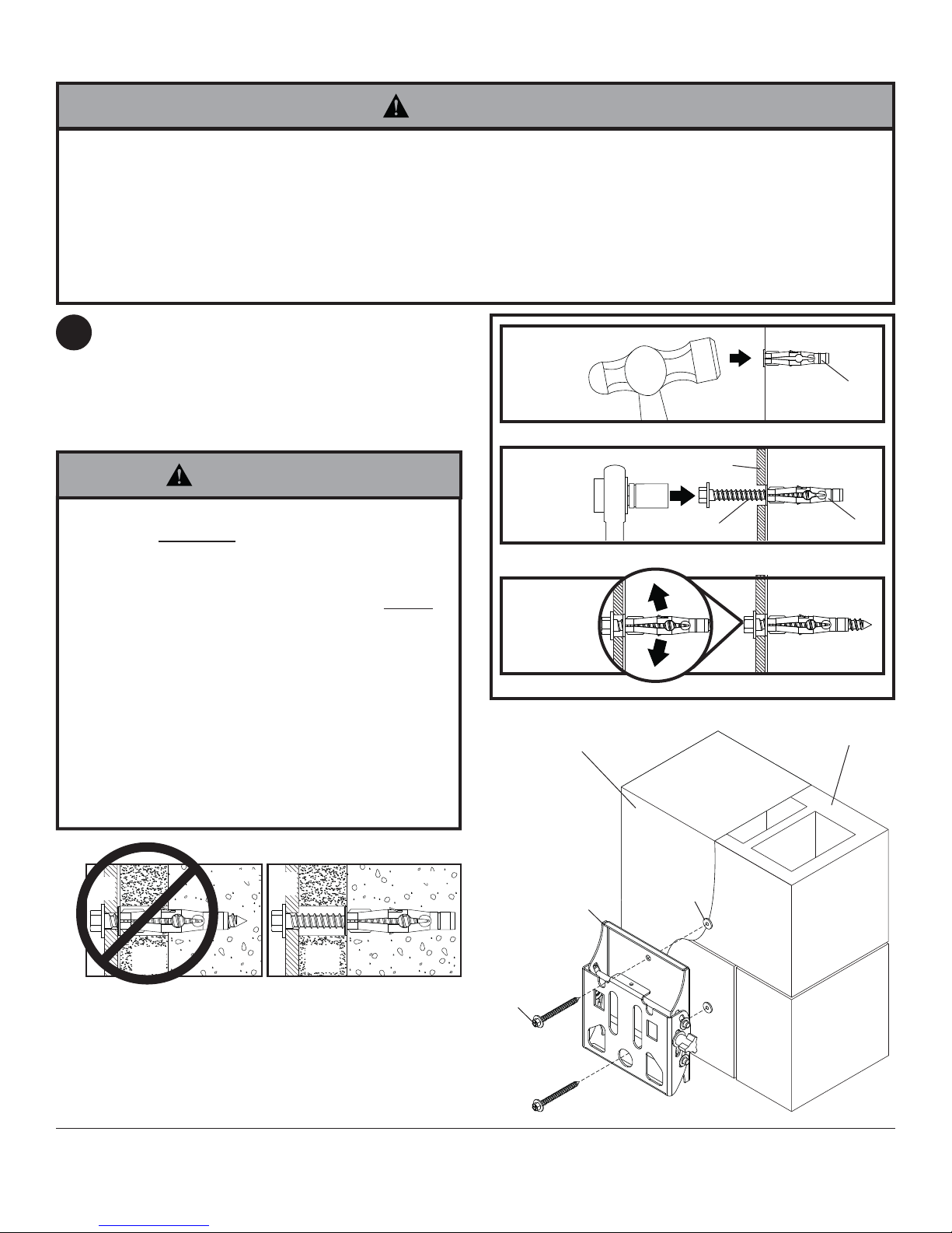
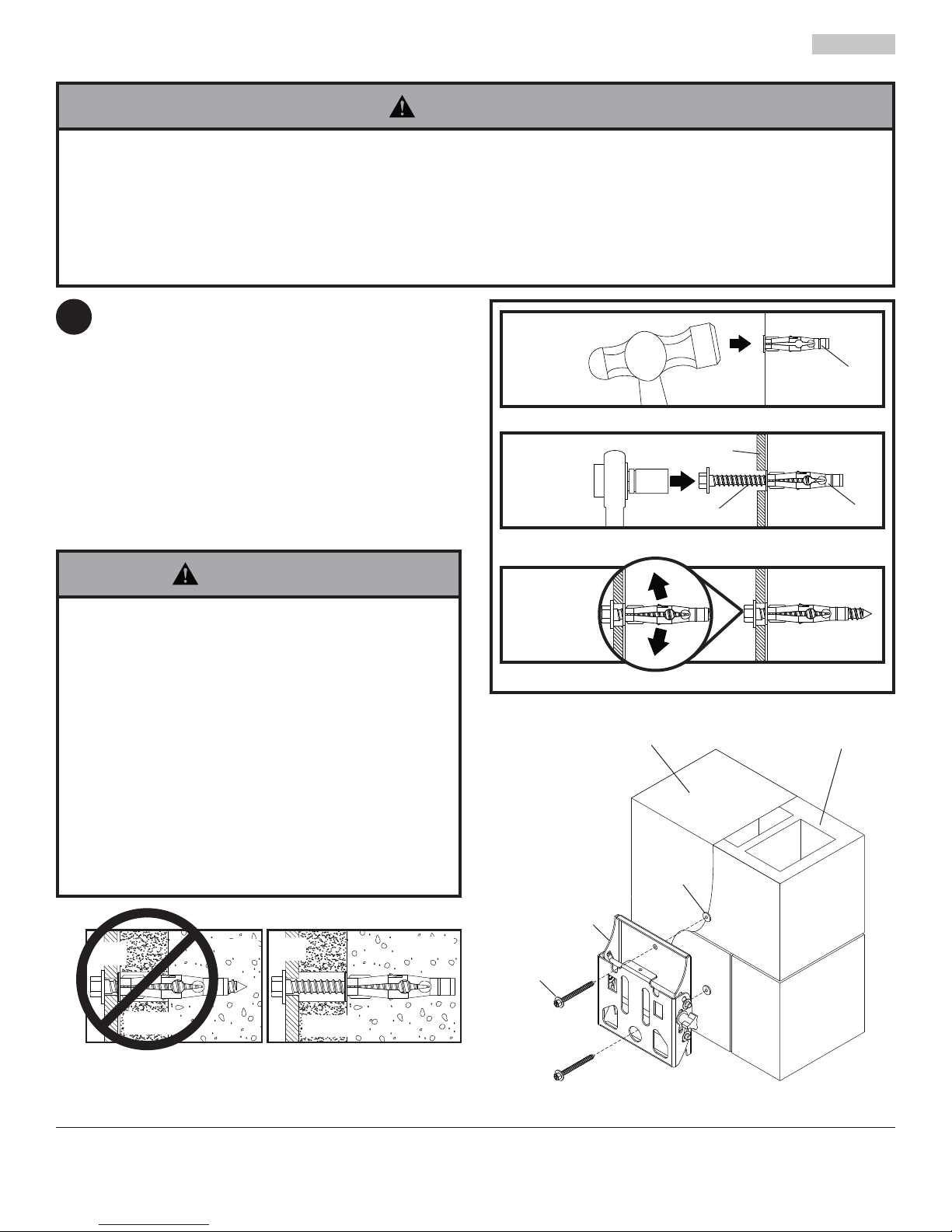
Installation to Solid Concrete or Cinder Block
WARNING
• When installing Peerless wall mounts on cinder block, verify that you have a minimum of 1-3/8" (35 mm) of actual
concrete thickness in the hole to be used for the concrete anchors. Do not drill into mortar joints! Be sure to mount
in a solid part of the block, generally 1" (25 mm) minimum from the side of the block. Cinder block must meet ASTM
C-90 specifi cations. It is suggested that a standard electric drill on slow setting is used to drill the hole instead of a
hammer drill to avoid breaking out the back of the hole when entering a void or cavity.
• Concrete must be 2000 psi density minimum. Lighter density concrete may not hold concrete anchor.
• Make sure that the wall will safely support four times the combined load of the equipment and all attached hardware
and components.
Make sure that tilt assembly (B) is level, use it as a
1
template to mark two mounting holes. Drill two 5/16"
(8 mm) dia. holes to a minimum depth of 2.5"
(64 mm). Insert anchors (D) in holes fl ush with wall
as shown (right). Place tilt assembly over anchors
and secure with two #14 x 2.5" screws (K). Level,
then tighten all fasteners.
1
Drill holes and insert anchors (D).
concrete
surface
D
WARNING
• Tighten screws so that wall plate is fi rmly attached,
but do not overtighten. Overtightening can damage
screws, greatly reducing their holding power.
• Never tighten in excess of 80 in. • lb (9 N.M.).
• Always attach concrete expansion anchors directly
to load-bearing concrete.
• Never attach concrete expansion anchors to
concrete covered with plaster, drywall, or other
fi nishing material. If mounting to concrete surfaces
covered with a fi nishing surface is unavoidable (not
evaluated by UL), the fi nishing surface must be
counterbored as shown below. Be sure concrete
anchors do not pull away from concrete when
tightening screws. If plaster/drywall is thicker than
5/8" (16 mm), custom fasteners must be supplied by
installer (not evaluated by UL).
INCORRECT CORRECT
wall
plate
concrete
wall
plate
concrete
2
B
K
Place plate (B) over anchors (D) and secure with screws (K).
3
Tighten all fasteners.
SOLID CONCRETE
B
D
CINDER BLOCK
D
plaster/
CUTAWAY VIEW
dry wall
plaster/
dry wall
5 of 34
K
ISSUED: 05-11-05 SHEET #: 201-9476-11 08-05-11
Page 6

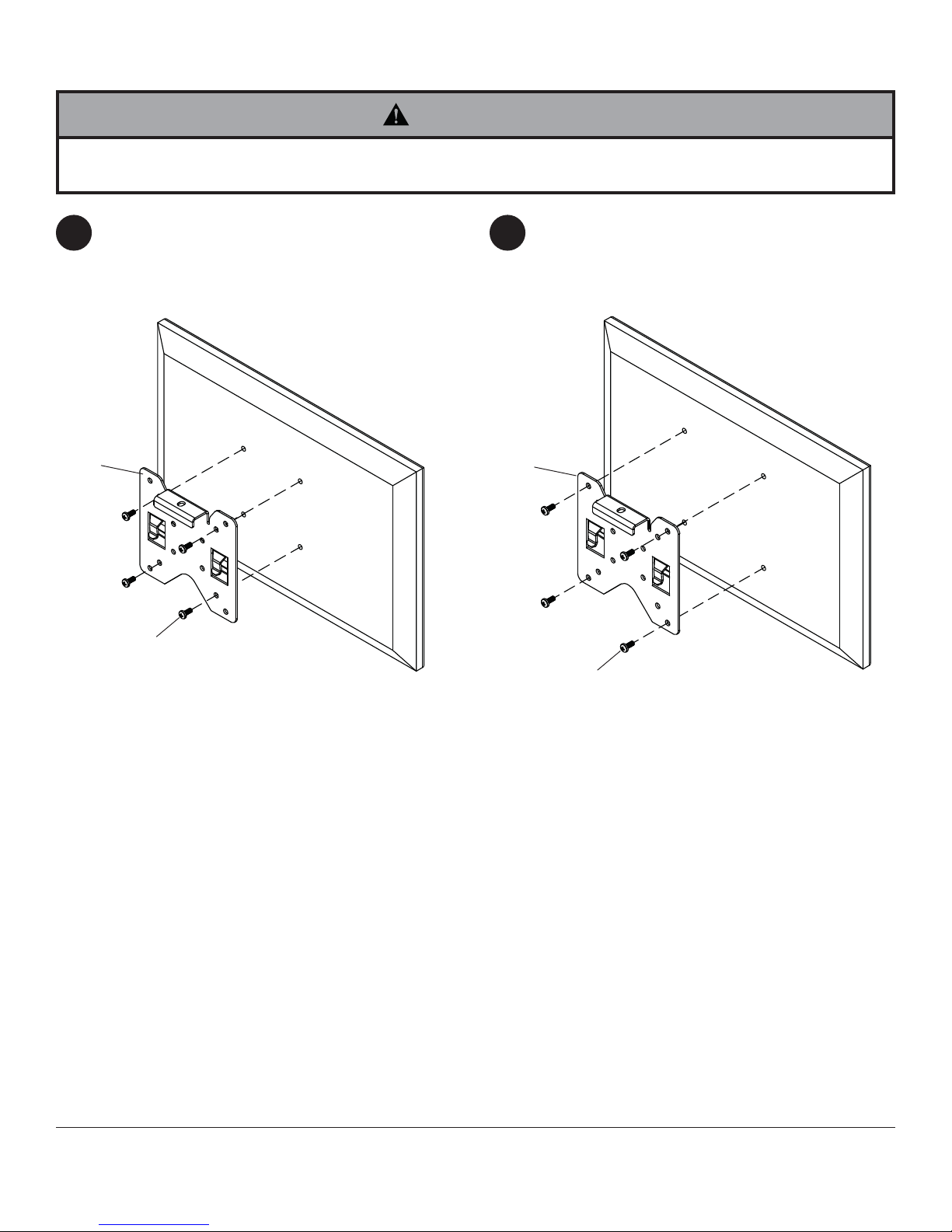
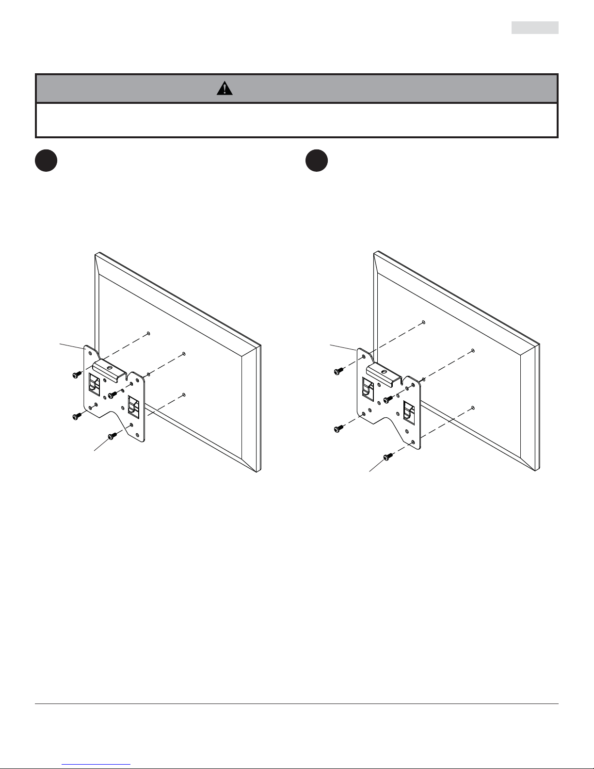
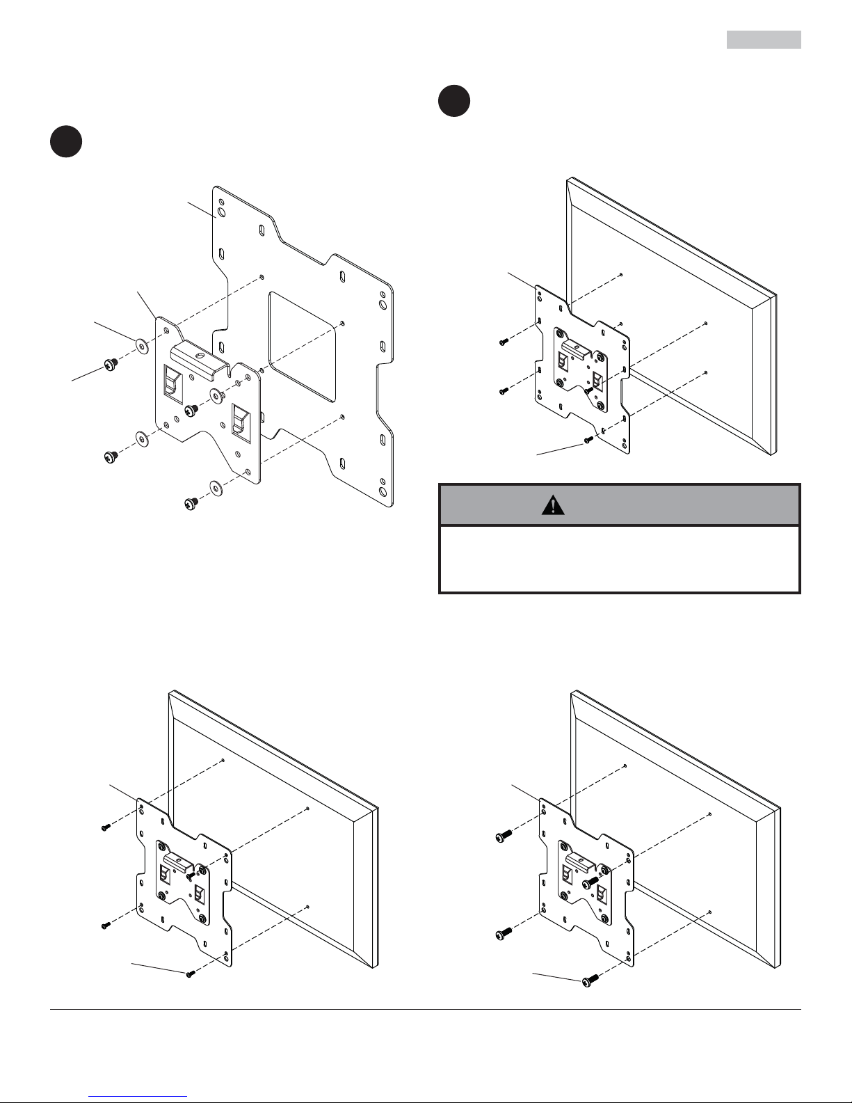
Attaching Adapter Plate to Display with VESA 200 or 200 x 100 Mounting Pattern
NOTE: For VESA 75 mm and 100 mm patterns, see
following page.
Attach hook bracket (A) onto adapter plate (C)
2
using four M5 x 6 mm screws (I) and #10 washers
(J) as shown.
C
A
J
I
FOR VESA 200 x 100 MOUNTING PATTERN:
3
Choose hole pattern as shown below. Attach
adapter plate (C) to back of display using four
M4 or M6 screws (E, F, G) as shown below.
C
E, F, G
WARNING
• If screws don't get three complete turns in the
display inserts or if screws bottom out and bracket is
still not tightly secured, damage may occur to display
or product may fail.
FOR VESA 200 MOUNTING PATTERN USING
M4 SCREWS:
Attach adapter plate (C) to back of display with four
M4 screws (E) using hole pattern shown below.
CC
FOR VESA 200 MOUNTING PATTERN USING
M6 OR M8 SCREWS:
Attach adapter plate (C) to back of display with four M6
or M8 screws (F, G, H) using hole pattern shown below.
E
6 of 34
F, G, H
ISSUED: 05-11-05 SHEET #: 201-9476-11 08-05-11
Page 7
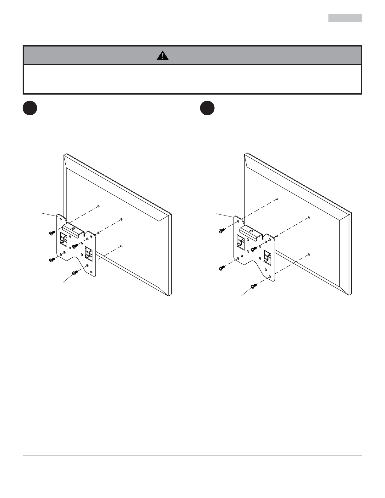
Attaching Hook Bracket to Display with VESA 75 or 100 Mounting Pattern
WARNING
• If screws don't get three complete turns in the display inserts or if screws bottom out and bracket is still not tightly
secured, damage may occur to display or product may fail.
FOR VESA® 75 MOUNTING PATTERN:
3 3
Choose hole pattern as shown below. Attach hook
bracket (A) to back of display using four M4 screws
(E) as shown below.
A
E
FOR VESA 100 MOUNTING PATTERN:
Choose hole pattern as shown below. Attach hook
bracket (A) to back of display using four M4 screws
(E) as shown below.
A
E
7 of 34
ISSUED: 05-11-05 SHEET #: 201-9476-11 08-05-11
Page 8
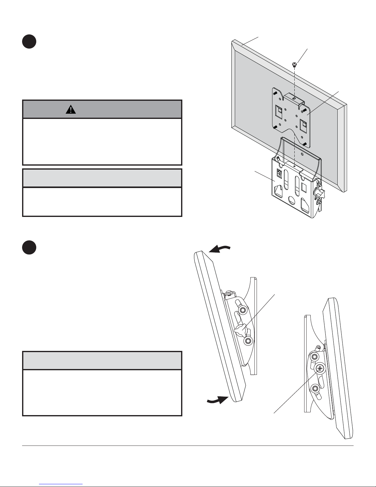
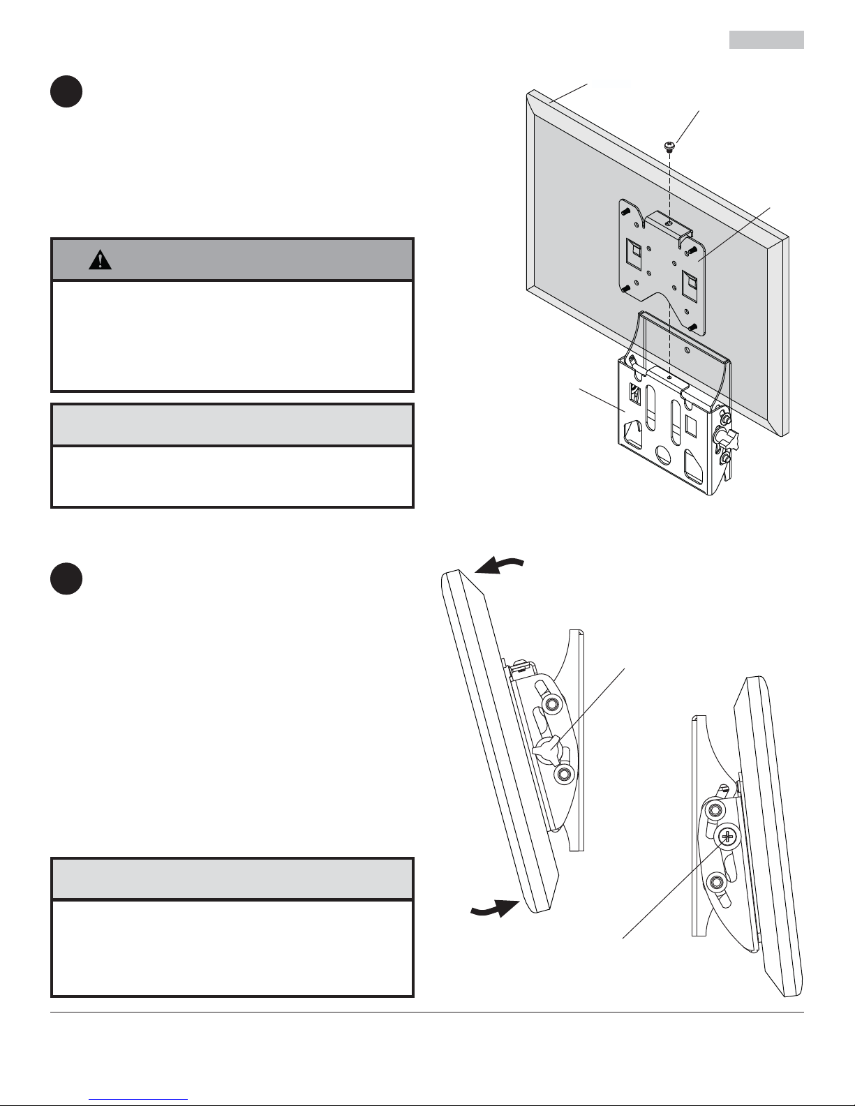
Installing and Removing Flat Panel Display
Attach display to tilt assembly (B). Tighten
4
M5 x 6 mm screw (I, L) to lock display to tilt
assemby.
For security installation tighten M5 x 6 mm socket
pin screw (L) using 4 mm security driver (M) to lock
display to tilt assemby.
To remove display from mount, loosen M5 screw
(I, L) and lift display off of mount.
WARNING
• Do not lift more weight than you can handle.
Use additional man power or mechanical lifting
equipment to safely handle placement of the display.
• Failure to lock hook bracket (A) with screw (I, L) can
cause display to come off mount if hit accidentally.
CAUTION
• Do not tighten screws with excessive force.
Overtightening can cause damage to mount. Tighten
screws to 20 in. • lb (2.26 N.M.) maximum torque.
DISPLAY
I, L
A
B
Adjusting the Tilt Angle of the Flat Panel Display
Adjust tension knob on right side of mount shown in
5
fi gure 5.1 to desired tension to balance your display
size and weight.
NOTE: If knob is inaccessible, remove display from
mount, adjust tension knob to desired tension to
balance your display size and weight, and reattach
display to mount as stated in step 4.
Push or pull from top or bottom of display to adjust
tilt as shown in fi gure 5.1. The tilt can be adjusted to
a maximum of 15° forward or 5° backward.
NOTE: To lock the display into the desired tilt
position, tighten tension screw on left side of mount
shown in fi gure 5.2 using phillips screw.
CAUTION
• Do not tighten screws with excessive force.
Overtightening can cause damage to mount. Tighten
screws to 40 in. • lb (4.5 N.M.) maximum torque.
• Be careful not to pinch fi ngers when pushing display
from the bottom.
fi g. 5.1
TENSION SCREW
TENSION KNOB
fi g. 5.2
8 of 34
All other brand and product names are trademarks or registered trademarks of their respective owners.
ISSUED: 05-11-05 SHEET #: 201-9476-11 08-05-11
© 2011, Peerless Industries, Inc. All rights reserved.
Peerless Industries, Inc.
2300 White Oak Circle
Aurora, Il 60502
www.peerlessmounts.com
Page 9
Installation et assemblage:
Soporte Universal de pared SmartMount™ con Capacidad de
Inclinación para Pantallas Planas de 22" a 40" (56 - 102 cm)
Modelos: ST632P, ST632P-S, ST632, ST632-S, SWV220/BK, SWV220/SI
Características:
• Sostiene pantallas planas de 22" a 40"
• Inclinación de para permitir la colocación y el ajuste de
la pantalla sin esfuerzo
• Funciones integradas de seguridad proporcionan
protección efi ciente contra el robo
2300 White Oak Circle • Aurora, Il 60502 • (800) 865-2112 • Fax: (800) 359-6500 • www.peerlessmounts.com
I
D
2
:
6
0
7
0
8
0
1
0
0
Máxima capacidad de UL carga: 115 lb (52.2 kg)
PUBLICADO: 05-11-05 HOJA #: 201-9476-11 08-05-11
Page 10
EspañolEspañol
NOTA: Lea la hoja de instrucciones completa antes de comenzar la instalación y el ensamblaje.
ADVERTENCIA
• No comience a instalar su producto de Peerless hasta haber leído y entendido las instrucciones y las advertencias
contenidas en la Hoja de Instalación. Si tiene alguna pregunta acerca de cualquiera de las instrucciones o las
advertencias, por favor
internacional, por favor, comuníquese con su distribuidor local.
• Este producto sólo debe ser instalado por una persona que tenga una buena aptitud mecánica, que tenga
experiencia en construcción básica de edifi cios y que entienda estas instrucciones en su totalidad.
• Asegúrese de que la superfi cie de apoyo sostendrá, con seguridad, la carga combinada del equipo y todos los
fi jadores y componentes.
• Nunca sobrepase la capacidad máxima de soportar carga. Vea la página 9.
• Si va a instalar el producto en una pared con montantes de madera, asegúrese de que los tornillos de montaje estén
anclados en el centro de los montantes. Se recomienda utilizar un localizador de montantes de "borde a borde".
• Siempre cuente con la ayuda de un asistente o utilice un equipo mecánico de izar para levantar y colocar el equipo
con más seguridad.
• Apriete los tornillos con fi rmeza, pero no en exceso. Apretarlos en exceso puede dañar los artículos y puede
disminuir signifi cativamente su fuerza de fi jación.
• Este producto está diseñado para uso en interiores solamente. Utilizar este producto en exteriores podría causar
fallas del producto y lesiones a individuos.
• Este producto fue diseñado para ser instalado en paredes con la siguiente construcción solamente:
CONSTRUCCIÓN DE LA PARED ACCESORIOS NECESARIOS
• Montante de madera Incluido
• Viga de madera Incluido
• Concreto macizo Incluido
• Bloque de hormigón de escorias Incluido
• Montante de metal No lo instale excepto con el juego de accesorios de Peerless para
montantes de metal - ACC215; (no evaluados por UL)
• Ladrillo Comuníquese con un profesional califi cado (no evaluados por UL)
• ¿Otra superfi cie o no está seguro? Comuníquese con un profesional califi cado (no evaluados por UL)
, llame a Servicio al Cliente de Peerless al 1-800-865-2112 si está en EE. UU. Si es un cliente
Herramientas necesarias para el ensamblaje
• localizador de montantes (se recomienda uno de "borde a borde")
• destornillador phillips
• taladro
• broca de 5/16" (8 mm) para paredes de concreto y de bloque de hormigón de escorias
• broca de 5/32" (4 mm) para paredes con montantes de madera
• nivel
Contenido
Lista de piezas......................................................................................................................................................................11
Instalación en una pared con montantes de madera .......................................................................................................... 12
Instalación en una pared de concreto macizo o de bloques de hormigón de escorias ....................................................... 13
Fijación de la placa adaptadora a pantallas con confi guraciones de montaje VESA® 200 ó 200 x 100 ............................ 14
Fijación de la placa de montaje a pantallas con confi guraciones de montaje VESA® 75 ó 100 ........................................ 15
Instalación y desinstalación de la pantalla plana ................................................................................................................ 16
10 de 34
PUBLICADO: 05-11-05 HOJA #: 201-9476-11 08-05-11
Page 11
Antes de comenzar, asegúrese de que su producto contiene todas las piezas que se muestran.
Lista de Piezas
Descripción Cant. N.° de pieza N.° de pieza N.° de pieza N.° de pieza
A soporte de gancho 1 095-1346
B inclinación de montaje 1
C placa adaptadora 1 095-P1721 095-4721
D anclaje para concreto 2
E tornillo phillips M4 x 10 mm 4 504-9012 504-9012 504-9012 504-9012
F tornillo phillips M6 x 12 mm 4 520-1128 520-1128 520-1128 520-1128
G tornillo phillips M6 x 20 mm 4 520-9402 520-9402 520-9402 520-9402
H tornillo phillips M8 x 10 mm 4 520-1605 520-1605 520-1605 520-1605
I tornillo phillips M5 x 6 mm 5 520-1023 520-1023 520-1023 520-1023
J arandela plana N.o 10 4 540-9400 540-9400 540-9400 540-9400
K tornillo para madera de 14 x 2.5" 2 5S1-015-C03
L tornillo pasador de cabeza hueca de
M destornillador de seguridad de 4 mm
Algunas partes pueden diferir un poco de las ilustradas.
M 1 - - 520-1114 520-1114
SWV220/BK SWV220/SI
ST632P,
095-0359
590-0320
1
- - 560-1133 560-1133
ST632P-S, ST632 ST632-S
095-4346
095-0360
590-0320
5S1-015-C03
095-1346
095-0359
095-P1721 095-4721
590-0320
5S1-015-C03
095-4346
095-0360
590-0320
5S1-015-C03
EspañolEspañol
C
L
M
FG HE
D
I
J
K
11 de 34
A
B
PUBLICADO: 05-11-05 HOJA #: 201-9476-11 08-05-11
Page 12

EspañolEspañol
Instalación en una pared con montantes de madera
ADVERTENCIA
• El instalador tiene que asegurarse de que la superfi cie de apoyo sostendrá, con seguridad, la carga combinada del equipo y todos
los fi jadores y componentes.
• Apriete los tornillos de madera de manera que la placa de pared se fi je fi rmemente, pero no en exceso. Apretarlos en exceso
puede dañar los tornillos y puede disminuir signifi cativamente su fuerza de fi jación.
• Nunca apriete a más de 80 pulg-lb (9 N•m).
• Asegúrese de que los tornillos de montaje estén anclados en el centro del montante. Se recomienda utilizar un localizador de
montantes de "borde a borde".
• Los accesorios para la instalación que se proveen son para fi jar el soporte a montantes de madera a través de tabique de yesocartón o yeso de espesor estándar. Los instaladores son responsables de suministrar los accesorios necesarios para otros tipos
de instalaciones (no evaluados por UL).
Utilice un localizador de montantes para localizar los bordes del montante. Se recomienda utilizar un localizador de
1
montantes de “borde a borde”. Tomando los bordes como punto de referencia, trace una línea vertical por el centro
del montante. Coloque la unidad de inclinación (B) en la pared para utilizarla como plantilla; asegúrese de que
los dos agujeros de montaje estén sobre la línea que trazó por el centro. Nivele la unidad de inclinación y marque
el centro de los dos agujeros. Taladre dos agujeros de 5/32" (4 mm) de diámetro y 2.5" (64 mm) de profundidad.
Asegúrese de que la unidad de inclinación esté nivelada, fíjela utilizando dos tornillos para madera de 14 x 2.5"
(K), como se muestra.
Pase al paso 2.
K
B
12 de 34
PUBLICADO: 05-11-05 HOJA #: 201-9476-11 08-05-11
Page 13

Instalación en una pared de concreto macizo o de bloques de hormigón
EspañolEspañol
de escorias
ADVERTENCIA
• Cuando vaya a instalar soportes de pared de Peerless en bloques de hormigón de escorias, asegúrese de que cuente con una
capa de concreto de un grosor mínimo de 1-3/8" en el agujero, que pueda usar para los anclajes para concreto. ¡No taladre en
juntas de argamasa! Asegúrese de hacer la instalación en la parte sólida del bloque, por lo general, a un mínimo de 1" (25 mm) del
extremo del bloque. Los bloques de hormigón de escorias tienen que cumplir las especifi caciones de la ASTM C-90. Se sugiere
utilizar un taladro eléctrico convencional a baja velocidad para hacer el agujero en vez de un taladro percutor para no perforar el
fondo del agujero al entrar en un vacío o una cavidad.
• El concreto tiene que tener una densidad mínima de 2,000 psi. Es posible que un concreto de menos densidad no sostenga el
anclaje para concreto.
• Asegúrese de que la superfi cie de apoyo sostendrá, con seguridad, la carga combinada del equipo y todos los fi jadores y
componentes.
Asegúrese de que la unidad de inclinación (B) esté
1
nivelada y utilícela como plantilla para marcar dos
agujeros de montaje. Taladre dos agujeros de 5/16"
(8 mm) de diámetro a una profundidad mínima
de 2.5" (64 mm). Inserte los anclajes (D) en los
agujeros a ras con la pared, como se muestra (a la
derecha). Coloque la unidad de inclinación sobre
los anclajes y fíjela con dos tornillos de 14 x 2.5"
(K). Nivele y apriete todos los sujetadores.
ADVERTENCIA
• Apriete los tornillos de manera que la placa de pared
se fi je fi rmemente, pero no en exceso. Apretarlos en
exceso puede dañar los tornillos y puede disminuir
signifi cativamente su fuerza de fi jación.
• Nunca apriete a más de 80 pulg-lb (9 N•m).
• Siempre fi je los anclajes para concreto directamente en la
pared que sostiene la carga.
• Nunca fi je los anclajes para concreto a una pared de concreto
recubierta con yeso, tabique de yeso-cartón u otro material de
acabado. Si es inevitable hacer la instalación en una superfi cie
de concreto recubierta con una superfi cie de acabado (no
evaluados por UL), la superfi
escariada, como se muestra abajo. Asegúrese de que los
anclajes para concreto no se separen del concreto cuando
apriete los tornillos. Si el grosor de la capa de yeso o tabique
de yeso-cartón tiene un grosor mayor de 5/8", el instalador
tiene que suministrar las fi jaciones especiales (no evaluados
por UL).
INCORRECTO
placa
de
pared
cie de acabado tiene que ser
concreto
placa
pared
de
CORRECTO
concreto
1
Perfore los agujeros y después inserte los anclajes (D).
2
B
K
Coloque la placa (B) sobre los anclajes (D) y fíjela con
los tornillos (K).
3
Apriete todas las fi jaciones.
CONCRETO MACIZO
BLOQUE DE
HORMIGÓN
DE ESCORIAS
D
B
K
superfi cie de
concreto
D
D
VISTA EN CORTE
yeso / tabique de yeso-cartón
13 de 34
PUBLICADO: 05-11-05 HOJA #: 201-9476-11 08-05-11
Page 14

Fijación de la placa adaptadora a pantallas con confi guraciones de
montaje VESA 200 ó 200 x 100
NOTA: En el caso de las confi guraciones de montaje
VESA® 75 mm y 100 mm, pase a la próxima página.
Fije el soporte de gancho (A) a la placa adaptadora
2
(C) usando cuatro tornillos de M5 x 6 mm (I) y
cuatro arandelas N.° 10 (J), como se muestra.
PARA LAS CONFIGURACION DE MONTAJE
3
VESA 200 X 100 MM:
Escoja una confi guración de agujeros, como se
muestra abajo. Fije la placa adaptadora (C) a la
parte trasera de la pantalla usando cuatro tornillos
de M4 o M6 (E, F, G), como se muestra abajo.
C
C
A
J
I
E, F, G
EspañolEspañol
ADVERTENCIA
• Si no se les da tres vueltas completas a los tornillos
en los insertos de la pantalla o si los tornillos topan
fondo y el soporte todavía no está fi rme, se podría
dañar la pantalla o el producto podría no funcionar
bien.
PARA LAS CONFIGURACION DE MONTAJE VESA 200
MM USANDO M4 SCREWS:
Fije la placa adaptadora (C) a la parte trasera de la
pantalla con cuatro tornillos de M4 (E) con usando
confi guración de agujeros.
CC
PARA LAS CONFIGURACION DE MONTAJE VESA 200
MM USANDO M6 O M8 SCREWS:
Fije la placa adaptadora (C) a la parte trasera de la
pantalla con cuatro tornillos de M6 o M8 (F, G, H) usando
confi guración de agujeros.
E
14 de 34
F, G, H
PUBLICADO: 05-11-05 HOJA #: 201-9476-11 08-05-11
Page 15
EspañolEspañol
Fijación del soporte de gancho a pantallas con confi guraciones de
montaje VESA® 75 ó 100
ADVERTENCIA
• Si no se les da tres vueltas completas a los tornillos en los insertos de la pantalla o si los tornillos topan fondo y el
soporte todavía no está fi rme, se podría dañar la pantalla o el producto podría no funcionar bien.
EN EL CASO DE LA CONFIGURACIÓN DE
2 2
MONTAJE VESA® 75:
Escoja un patrón de agujeros, como se muestra
abajo. Fije la soporte de gancho (A) a la parte
trasera de la pantalla usando cuatro tornillos de
M4 (E), como se muestra abajo.
A
EN EL CASO DE LA CONFIGURACIÓN DE
MONTAJE VESA® 100:
Escoja un patrón de agujeros, como se muestra
abajo. Fije la soporte de gancho (A) a la parte
trasera de la pantalla usando cuatro tornillos de
M4 (E), como se muestra abajo.
A
E
15 de 34
E
PUBLICADO: 05-11-05 HOJA #: 201-9476-11 08-05-11
Page 16

Instalación y desinstalación de la pantalla plana
Fije la pantalla en la unidad de inclinación (B).
4
Apriete el tornillo de M5 x 6 mm (I, L) para fi jar la
pantalla en la unidad de inclinación.
Para realizar una instalación segura, apriete el
tornillo pasador de cabeza hueca de
M5 x 6 mm (L) con un destornillador de seguridad
de 4 mm (O) para fi jar la pantalla en la unidad de
inclinación.
Para quitar la pantalla del soporte, afl oje el tornillo
(I, L) y levante la pantalla para sacarla del soporte.
ADVERTENCIA
• No levante más peso del que puede manejar. Cuente con
otra persona que lo ayude o utilice un equipo mecánico de
izar para levantar y colocar la pantalla con seguridad.
• No trabar el soporte de gancho (A) con el tornillo (I, L)
puede causar que la pantalla se caiga del soporte si recibe
un golpe accidental.
ATENCIÓN
EspañolEspañol
PANTALLA
I, L
A
B
• No apriete los tornillos con fuerza excesiva. Apretarlos en
exceso puede dañar el soporte. Apriete los tornillos a un
máximo de 20 pulg-lb (2.26 N•m) de par torsor.
Ajuste del ángulo de inclinación de la pantalla de panel plano
Ajuste la perilla de tensión que se encuentra en el
5
lado del soporte que se muestra en la fi gura 5.1
al grado de tensión deseado para balancear el
tamaño y el peso de la pantalla.
NOTA: Si mando es inaccesible, quitar la pantalla
de montar, ajustar la tensión de mando de la
tensión deseada para equilibrar su peso y tamaño
de pantalla, pantalla y volver a montar como se
indica en el paso 4 Mueva la parte superior o la
parte inferior de la pantalla tirando de la misma o
empujándola para ajustar la inclinación, como se
muestra. La inclinación se puede ajustar hasta un
máximo de 15° hacia delante o de 5° hacia atrás.
NOTA: Para bloquear la pantalla en la posición de
la inclinación deseada, apriete el tornillo de tensión
en el lado izquierdo de montaje se muestra en la
fi gura 5.2 utilizando el tornillo phillips.
fi g. 5.1
PERILLA DE TENSIÓN
fi g. 5.2
ATENCIÓN
• No apriete los tornillos con fuerza excesiva. Apretarlos en
exceso puede dañar el soporte. Apriete los tornillos a un
máximo de 40 pulg-lb (4.5 N•m) de par torsor.
• Tenga cuidado de no pincharse los dedos cuando extienda y
recoja el soporte contra la pared.
TORNILLO DE TENSIÓN
16 de 34
Cualesquiera otras marcas y nombres de productos son marcas comerciales o registradas de sus respectivos dueños.
PUBLICADO: 05-11-05 HOJA #: 201-9476-11 08-05-11
© 2011, Peerless Industries, Inc. Todos los derechos reservados.
Peerless Industries, Inc.
2300 White Oak Circle
Aurora, Il 60502
www.peerlessmounts.com
Page 17

Installation et Montage:
Support mural inclinable universel SmartMount™ pour écrans
plats de 22 à 40 po (56 - 102 cm)
Modèles: ST632P, ST632P-S, ST632, ST632-S, SWV220/BK, SWV220/SI
Caractéristiques:
• Convient aux écrans plats de 22 à 40 po
• Inclinaison par simple appui sur un réglage et un
positionnement faciles de l’écran
• Fonctions sécuritaires intégrées procurant une
dissuasion effi cace contre le vol
2300 White Oak Circle • Aurora, Il 60502 • (800) 865-2112 • Fax: (800) 359-6500 • www.peerlessmounts.com
I
D
2
:
6
0
7
0
8
0
1
0
0
Capacité de charge maximale UL préconisée: 115 lb (52.2 kg)
PUBLIÉ LE: 05-11-05 FEUILLE no: 201-9476-11 08-05-11
Page 18
Français
REMARQUE: lisez entièrement la fi
che d’instructions avant de commencer l’installation et l’assemblage.
AVERTISSEMENT
• Ne commencez pas à installer votre produit Peerless avant d’avoir lu et assimilé les instructions et les avertissements
contenus dans cette fi
veuillez appeler le service à la clientèle de Peerless au 1-800-865-2112; tous les clients internationaux sont priés de
contacter leur distributeur local.
• Ce produit doit être installé uniquement par quelqu’un possédant une bonne aptitude à la mécanique, une expérience
de la construction immobilière et ayant bien compris ces instructions.
• Assurez-vous que la surface de support puisse soutenir sans danger la charge totale de l’équipement ainsi que des
pièces et composants qui y sont attachés.
• Ne dépassez jamais la capacité de charge maximum. Reportez-vous à la page 17.
• Lors d’une installation sur un mur à montants en bois, assurez-vous que les vis de montage sont ancrées au centre
des montants. L’utilisation d’un localisateur de montants « bord à bord » est fortement recommandée.
• Pour lever et positionner l’équipement en toute sécurité, faites-vous toujours aider par une autre personne ou utilisez
un dispositif de levage mécanique.
• Serrez fermement les vis, mais sans excès. Un serrage excessif peut endommager les composants et en réduire
considérablement la capacité de support.
• Ce produit est conçu uniquement pour un usage intérieur. L’utilisation de ce produit à l’extérieur peut causer une
défaillance du produit et des blessures corporelles.
• Ce produit a été conçu uniquement pour une installation sur les types de murs ci-dessous :
TYPE DE MUR PIÈCES DE FIXATION REQUISES
• Montant en bois Incluses
• Poutre en bois Incluses
• Béton plein Incluses
• Bloc de béton de mâchefer Incluses
• Montant métallique Ne pas installer sur ce type de mur sauf à l’aide de l’ensemble d’accessoires
Peerless pour montants métalliques - ACC215; (non évalué UL)
• Brique Contacter un professionnel qualifi é (non évalué UL)
• Autre, ou vous n’êtes pas sûr ? Contacter un professionnel qualifi é (non évalué UL)
che d’installation. Pour toute question concernant les instructions ou les avertissements,
Outils nécessaires au montage
• localisateur de montants (un localisateur de montants « bord à bord » est recommandé)
• tournevis phillips
• perceuse
• foret de 5/32 po (4 mm) pour les murs à montants en bois
• foret de 5/16 po (8 mm) pour les murs à block de béton
• niveau
Tabla de contenido
Lista de piezas......................................................................................................................................................................19
Installation sur un mur a simple montant en bois ................................................................................................................. 20
Installation sur du béton plein ou un bloc de béton de mâchefer ......................................................................................... 21
Fixation d’une plaque adaptatrice sur un écran à confi guration de montage VESA 200 ou 200 x 100 ................................22
Fixation d’un crochet de support sur un écran à confi guration de montage VESA 75 ou 100 .............................................23
Installation de l’écran plat sur la plaque murale ...................................................................................................................24
18 sur 34
PUBLIÉ LE: 05-11-05 FEUILLE n°: 201-9476-11 08-05-11
Page 19

Avant de commencer, veillez à ce que toutes les pièces énumérées soient incluses.
Français
Liste des pièces
Description Qté
A Crochet de support 1 095-1346
B ensemble d’inclinaison 1 095-0359
C plaque adaptatrice 1 095-P1721 095-4721
D chevilles d'ancrage pur béton 2
E vis cruciforme M4 x 10 mm 4 504-9012 504-9012 504-9012 504-9012
F vis cruciforme M6 x 12 mm 4 520-1128 520-1128 520-1128 520-1128
G vis cruciforme M6 x 20 mm 4 520-9402 520-9402 520-9402 520-9402
H vis cruciforme M8 x 10 mm 4 520-1605 520-1605 520-1605 520-1605
I vis cruciforme M5 x 6 mm 5 520-1023 520-1023 520-1023 520-1023
J rondelle nº 10 4 540-9400 540-9400 540-9400 540-9400
K vis à bois no 14 x 2,5 po 2 5S1-015-C03
L vis à tête creuse M5 x 6 mm 1 - - 520-1114 520-1114
M embout de sécurité de 4 mm 1 - - 560-1133 560-1133
Les pièces peuvent différer légèrement de l’illustration.
SWV220/BK SWV220/SI
ST632P,
pièces no
590-0320
o
ST632P-S, ST632 ST632-S
pièces no
095-4346
095-0360
590-0320
5S1-015-C03
o
pièces no
095-1346
095-0359
095-P1721 095-4721
590-0320
5S1-015-C03
o
pièces no
095-4346
095-0360
590-0320
5S1-015-C03
o
C
L
M
FG HE
D
I
J
K
19 sur 34
A
B
PUBLIÉ LE: 05-11-05 FEUILLE n°: 201-9476-11 08-05-11
Page 20

Français
Installation sur un mur à montant en bois
AVERTISSEMENT
• L’installateur doit s’assurer que la surface de support pourra soutenir sans danger la charge combinée de l’équipement, de toute
sa visserie et de tous ses composants.
• Serrez les vis à bois de manière que la plaque murale soit fermement fi xée, mais sans excès. Un serrage excessif peut
endommager les vis et en réduire considérablement le pouvoir de maintien.
• Ne serrez jamais à plus de 9 Nm (80 po-lb).
• Assurez-vous que les vis de montage sont ancrées au centre des montants. L’usage d’un localisateur de montants
« bord à bord » est fortement conseillé.
• La visserie est fournie pour fi xer la monture à travers une cloison sèche ou du plâtre d’épaisseur standard et dans des montants
en bois. Il appartient aux installateurs de fournir la visserie nécessaire pour d’autres types de situations (non évalué UL).
Utilisez un localisateur de montants pour repérer les bords du montant. L’usage d’un localisateur bord à bord est
1
fortement conseillé. En fonction de ses bords, tracez une ligne verticale le long du centre du montant. Utilisez
l’ensemble d’inclinaison (B) comme gabarit et placez-le sur le mur, en vous assurant que les deux trous de
montage se trouvent sur l’axe du montant. Mettez l’ensemble d’inclinaison de niveau et marquez le centre des trois
trous. Percez deux trous de 4 mm (5/32 po) de diamètre et de 64 mm (2,5 po) de profondeur. Assurez-vous que
l’ensemble d’inclinaison est de niveau, fi xez-le à l’aide de deux vis à bois nº 14 x 2,5 po (K), comme illustré.
Passez à l’étape 2.
K
B
20 sur 34
PUBLIÉ LE: 05-11-05 FEUILLE n°: 201-9476-11 08-05-11
Page 21

Français
Installation sur du béton plein ou un bloc de béton de mâchefer
AVERTISSEMENT
• Si vous installez des montures murales Peerless sur un bloc de béton de mâchefer, vérifi ez que vous disposez d’une épaisseur
de béton d’au moins 0,34 cm (1 3/8 po) dans le trou destiné aux ancrages de béton. Ne percez pas dans les joints de mortier !
Veillez à effectuer le montage dans une partie pleine du bloc, généralement à au moins 2,5 cm (1 po) du côté du bloc. Le bloc de
béton de mâchefer doit être conforme aux spécifi cations de l’ASTM C-90. Pour percer le trou, il est conseillé d’utiliser une perceuse
électrique standard sur un réglage bas au lieu d’un marteau perforateur, afi n d’éviter de briser la partie arrière du trou lorsque vous
pénétrez un vide ou une cavité.
• Le béton doit avoir une densité minimale de 2 000 psi. Un béton de densité moindre risquerait de ne pas retenir un ancrage de
béton.
• Assurez-vous que la surface de support pourra soutenir sans danger la charge combinée de l’équipement, de toute sa visserie et
de tous ses composants.
Assurez-vous que l’ensemble d’inclinaison (B) est
1
de niveau, utilisez-le comme gabarit pour marquer
les deux trous de montage. Percez deux trous
de 8 mm (5/16 po) de diamètre à une profondeur
minimum de 64 mm (2,5 po). Insérez les ancrages
(D) dans les trous au ras du mur, comme illustré
(à droite). Placez l’ensemble d’inclinaison sur les
ancrages et fi xez-le à l’aide de deux vis nº 14 x 2,5
po (K). Mettez-le de niveau, puis serrez toutes les
fi xations.
AVERTISSEMENT
• Serrez les vis de manière que la plaque murale soit
fermement fi xée, mais sans excès. Un serrage excessif
peut endommager les vis et en réduire considérablement le
pouvoir de maintien.
• Ne serrez jamais à plus de 9 Nm (80 po-lb).
• Fixez toujours des ancrages de béton directement sur du
béton porteur.
• Ne fi xez jamais d’ancrages sur du béton recouvert de plâtre,
une cloison sèche ou autre matériau de fi nition. Si vous
ne pouvez pas éviter d’effectuer le montage sur du béton
recouvert d’une surface de fi nition (non évalué UL), celle-ci
doit être chambrée, comme indiqué ci-dessous. Assurezvous que les ancrages de béton ne se séparent pas du
béton lorsque vous serrez les vis. Si l’épaisseur du plâtre /
de la cloison sèche dépasse 1,5 cm (5/8 po), des fi xations
adaptées devront être fournies par l’installateur (non évalué
UL).
1
Percez des trous et insérez les ancrages (D).
2
B
K
Placez la plaque (B) sur les ancrages (D) et fi
3
Serrez toutes les fi xations.
BÉTON PLEIN
surface en
béton
D
D
xez avec des vis (K).
BLOC DE BÉTON
DE MÂCHEFER
INCORRECT
plaque
mural
plâtre /
VUE EN COUPE
cloison sèche
béton
plaque
mural
plâtre /
cloison sèche
CORRECT
béton
21 sur 34
D
B
K
PUBLIÉ LE: 05-11-05 FEUILLE n°: 201-9476-11 08-05-11
Page 22

Fixation de la plaque d’adaptation à un écran compatible à la norme
de montage VESA 200 ou 200 x 100
Français
REMARQUE : Pour les confi gurations VESA 75 mm et
100 mm, consultez la page suivante.
Fixez le crochet de support (A) sur la plaque
2
adaptatrice (C) à l’aide de quatre vis M5 x 6 mm (I)
et de rondelles nº 10 (J) comme illustré
C
A
J
I
CONFIGURATION DE MONTAGE
3
VESA® 200 x 100 :
Choisissez la confi guration de trous illustrée cidessous. Fixez la la plaque adaptatrice (C) au dos
de l’écran à l’aide de quatre vis M4 ou M6 (E, F, G)
comme illustré ci-dessous.
C
E, F, G
AVERTISSEMENT
• Si les vis ne sont pas enfoncées de trois tours
complets dans les inserts ou si elles sont serrées
au maximum sans parvenir à fi xer solidement
le support, l’écran peut être abîmé ou le produit
détérioré.
CONFIGURATION DE MONTAGE VESA® 200 L'AIDE
DE VIS M4:
Fixez la la plaque adaptatrice (C) au dos de l’écran à l’aide
de quatre vis M4 (E) confi guración a través de agujeros.
CONFIGURATION DE MONTAGE VESA® 200 L'AIDE
DE VIS M6 OU M8:
Fixez la la plaque adaptatrice (C) au dos de l’écran à l’aide
de quatre vis M6 ou M8 (F, G, H) confi guración a través de
agujeros.
CC
E
22 sur 34
F, G, H
PUBLIÉ LE: 05-11-05 FEUILLE n°: 201-9476-11 08-05-11
Page 23

Français
Fixation d’un crochet de support sur un écran à confi guration de
montage VESA 75 ou 100
ADVERTISSEMENT
• Si les vis ne sont pas enfoncées de trois tours complets dans les inserts ou si elles sont serrées au maximum sans
parvenir à fi xer solidement la plaque adaptatrice, l’écran peut être abîmé ou le produit détérioré.
CONFIGURATION DE MONTAGE VESA® 75 :
2 2
Choisissez la confi guration de trous illustrée
cidessous. Fixez le crochet de support (A) à l’arrière
de l’écran à l’aide de quatre vis M4 (E), comme
illustré ci-dessous.
A
CONFIGURATION DE MONTAGE VESA 100:
Choisissez la confi guration de trous illustrée
cidessous. Fixez le crochet de support (A) à l’arrière
de l’écran à l’aide de quatre vis M4 (E), comme
illustré ci-dessous.a
A
E
23 sur 34
E
PUBLIÉ LE: 05-11-05 FEUILLE n°: 201-9476-11 08-05-11
Page 24
Montage et démontage d’un écran plat
Fixez l’écran sur l’ensemble d’inclinaison (B).
4
Serrez la vis M5 x 6 mm (I, L) pour fi xer l’écran sur
l’ensemble d’inclinaison.
Pour consolider le tout, serrez la vis à tête creuse
M5 x 6 mm (L) à l’aide de l’embout de sécurité (M),
ce qui fi xera l’écran sur l’ensemble d’inclinaison.
Pour retirer l’écran du support, desserrez la vis (I, L)
et soulevez-le hors du support.
ADVERTISSEMENT
• Ne soulevez pas plus de poids que vous ne pouvez en
manipuler. Faites-vous aider ou utilisez un équipement
mécanique pour placer l’écran en toute sécurité.
• Si les crochets de support (A) ne sont pas fi xés avec la
vis (I, L), l’écran pourrait tomber du support, s’il est heurté
accidentellement.
ATTENTION
Français
ÉCRAN
I, L
A
B
• N’employez pas une force excessive pour serrer les vis.
Un serrage excessif peut endommager le support. Serrez
les vis à un couple maximum de 2,26 Nm (20 po-lb).
Réglage de l’inclinaison d’un écran plat
Réglez le bouton situé sur le côté droit du support
5
illustré sur la fi gure 5.1 à la tension désirée pour
équilibrer la taille et le poids de l’écran.
Remarque : Si le bouton est inaccessible, enlevez
l’écran du support, réglez le bouton sur la tension
désirée pour équilibrer la taille et le poids de l’écran
et remettez l’écran sur le support comme indiqué à
l’étape 4.
Poussez ou tirez depuis le haut ou le bas de l’écran
pour régler l’inclinaison, comme illustré à la fi gure
5.1. L’inclinaison peut être réglée à un maximum de
15° à l’avant ou 5° à l’arrière.
Remarque : Pour verrouiller l’écran dans la position
d’inclinaison désirée, serrez la vis de tension située
sur le côté gauche du support illustré à la fi gure 5.2
à l’aide d’un tournevis cruciforme.
fi g. 5.1
BOUTON DE
TENSION
fi g. 5.2
ATTENTION
• N’employez pas une force excessive pour serrer les vis. Un
serrage excessif peut endommager le support. Serrez les
vis à un couple maximum de 4,5 Nm (40 po-lb).
• Prenez garde à ne pas vous pincer les doigts lorsque vous
poussez l’écran depuis le bas.
VIS DE TENSION
24 sur 34
Tous les autres noms de marques et de produits sont des marques de commerce ou déposées de leurs propriétaires respectifs.
PUBLIÉ LE: 05-11-05 FEUILLE n°: 201-9476-11 08-05-11
© 2011, Peerless Industries, Inc. Tous droits réservés.
Peerless Industries, Inc.
2300 White Oak Circle
Aurora, Il 60502
www.peerlessmounts.com
Page 25

Anbringung und Zusammenbau:
SmartMount™-Universal-Wandkipphalter für Flachbildschirme
von 22 - 40 Zoll (56 - 102 cm)
Modelle: ST632P, ST632P-S, ST632, ST632-S, SWV220/BK, SWV220/SI
Merkmale:
• Für Flachbildschirme von 22 - 40 Zoll
• Mühelose Positionierung und Einstellung des Bildschirms
• Integrierte Sicherheitsfunktionen bieten wirksame
Diebstahlsicherung
2300 White Oak Circle • Aurora, Il 60502 • (800) 865-2112 • Fax: (800) 359-6500 • www.peerlessmounts.com
I
D
2
:
6
0
7
0
8
0
1
0
0
Max. UL Tragfähigkeit: 115 lb (52.2 kg)
AUSGEGEBEN: 05-11-05 BLATT NR.: 201-9476-11 08-05-11
Page 26
Deutsch
HINWEIS: Lesen Sie die gesamte Anleitung, bevor Sie mit der Anbringung und dem Zusammenbau beginnen.
ACHTUNG
• Beginnen Sie mit der Anbringung Ihres Peerless-Produkts erst, nachdem Sie die in dieser Montageanleitung
enthaltenen Anleitungen und Achtungshinweise gelesen und sich gründlich mit ihnen vertraut gemacht haben. Falls
Sie Fragen hinsichtlich irgendeiner der Anleitungen oder Achtungshinweise haben, wenden Sie sich in den USA bitte
an den Peerless-Kundendienst unter der Rufnummer 1-800-865-2112. Kunden im Ausland wenden sich bitte an den
örtlichen Vertragshändler.
• Dieses Produkt darf nur von Personen mit guten mechanischen Fähigkeiten montiert werden, die über Erfahrung in
den Grundlagen der Baukonstruktion verfügen und diese Anleitungen vollkommen verstehen.
• Vergewissern Sie sich, dass die tragende Fläche das Gesamtgewicht der Geräte und allen daran angebrachten
Befestigungsteilen und Komponenten sicher tragen kann.
• Die maximale Tragfähigkeit darf niemals überschritten werden. Siehe Seite 25.
• Achten Sie bei der Anbringung an Holzständern darauf, dass die Befestigungsschrauben jeweils in der Mitte der
Holzständer verankert sind. Am besten eignet sich ein Balkenfi nder mit genauer Kantenanzeige.
• Ziehen Sie immer eine zusätzliche Person heran oder verwenden Sie mechanische Hebegeräte, um Geräte sicher zu
heben und zu positionieren.
• Ziehen Sie die Schrauben fest an, ohne sie zu überdrehen. Durch Überdrehen können die Teile beschädigt werden,
wodurch ihr Haltevermögen stark reduziert wird.
• Dieses Produkt ist nur für den Gebrauch innerhalb von Gebäuden bestimmt. Eine Verwendung dieses Produkts im
Freien kann zu Produktausfall und Personenschaden führen.
• Dieses Produkt wurde nur für die Anbringung an den folgenden Wandkonstruktionen ausgelegt:
WANDKONSTRUKTION ERFORDERLICHE BEFESTIGUNGSTEILE
• Holzständer Inbegriffen
• Holzbalken Inbegriffen
• Massivbeton Inbegriffen
• Porenbetonstein Inbegriffen
• Metallständer Nur mit metallständer-zubehörsatz von Peerless anbringen - ACC215;
(nicht UL-betwertet)
• Ziegel Qualifi zierten fachmann konsultieren (nicht UL-betwertet)
• Andere oder nicht sicher? Qualifi zierten fachmann konsultieren (nicht UL-betwertet)
Für den Zusammenbau erforderliche Werkzeuge
• Balkenfi nder (Balkenfi nder mit genauer Kantenanzeige empfohlen)
• Kreuzschlitzschraubendreher
• Bohrer
• 5/16 Zoll (8 mm) Bit für Beton- und Porenbetonsteinwand
• 5/32 Zoll (4 mm) Bit für Holzständerwand
• Wasserwaage
Inhaltsverzeichnis
Teileliste ............................................................................................................................................................................... 27
Anbringung an Wand mit einer Holzständerreihe ................................................................................................................ 28
Anbringung an Massivbeton oder Porenbetonstein ............................................................................................................ 29
Befestigung von Adapterplatte an Bildschirm unter Verwendung von VESA-Montagemuster 200 oder 200 x 100 ............ 30
Befestigung der Hakenhalterung am Bildschirm unter Verwendung von VESA-Montagemuster 75 oder 100 ................... 31
Anbringung und Abnahme des Flachbildschirms ................................................................................................................ 32
26 von 34
AUSGEGEBEN: 05-11-05 BLATT NR.: 201-9476-11 08-05-11
Page 27
Deutsch
Vergewissern Sie sich vor Beginn der Arbeiten, dass alle dargestellten Teile mit Ihrem Produkt mitgeliefert wurden.
Teileliste
Beschreibung Anz. Teile Nr.
A Hakenhalterung 1 095-1346
B Kippeinheit 1
C Adapterplatte 1 095-P1721 095-4721 095-P1721 095-4721
D Betondübel 2 590-0320
E M4 x 10 mm Schrauben 4 504-9012 504-9012 504-9012 504-9012
F M6 x 12 mm Schrauben 4 520-1128 520-1128 520-1128 520-1128
G M6 x 20 mm Schrauben 4 520-9402 520-9402 520-9402 520-9402
H M8 x 10 mm Schraube 4 520-1605 520-1605 520-1605 520-1605
I M5 x 6 mm Schrauben 5 520-1023 520-1023 520-1023 520-1023
J Unterlegscheiben Nr. 10 4 540-9400 540-9400 540-9400 540-9400
K #14 x 2,5 Zoll Holzschraube 2 5S1-015-C03
L M5 x 6 mm Schrauben 1 - - 520-1114 520-1114
M 4 mm Sicherheitstreiber 1 - - 560-1133 560-1133
Die Teile können etwas anders als in der Abbildung aussehen.
SWV220/BK SWV220/SI
ST632P,
095-0359
ST632P-S, ST632 ST632-S
Teile Nr.
095-4346
095-0360
590-0320
5S1-015-C03
Teile Nr.
095-1346
095-0359
590-0320
5S1-015-C03
Teile Nr.
095-4346
095-0360
590-0320
5S1-015-C03
C
L
M
FG HE
D
I
J
K
27 von 34
A
AUSGEGEBEN: 05-11-05 BLATT NR.: 201-9476-11 08-05-11
B
Page 28

Deutsch
Anbringung an Wänden mit einer Holzständerreihe
ACHTUNG
• Bei der Anbringung muss darauf geachtet werden, dass die Wand die kombinierte Last von Bildschirm und allen Befestigungsteilen und
-komponenten tragen kann.
• Ziehen Sie die Schrauben fest genug an, dass die Wandplatte sicher befestigt ist, doch ohne sie zu überdrehen. Durch Überdrehen können die
Schrauben beschädigt werden, wodurch ihr Haltevermögen stark reduziert wird.
• Das Drehmoment darf 80 in. • lb (9 Nm.) auf keinen Fall überschreiten.
• Achten Sie darauf, dass die Befestigungsschrauben jeweils in der Mitte der Holzständer verankert werden. Am besten eignet sich ein Balkenfi nder
mit genauer Kantenanzeige.
• Die mitgelieferten Befestigungsteile sind für die Befestigung des Halters durch Trocken- oder Putzwand standardmäßiger Stärke in Holzständer
vorgesehen. Für die Anbringung an anders konstruierten Wänden müssen andere (nicht UL-zugelassene) Befestigungsteile verwendet werden.
Bestimmen Sie die Kanten des Ständers mithilfe eines Balkenfi nders. Am besten eignet sich ein Balkenfi nder
1
mit genauer Kantenanzeige. Verwenden Sie die Kanten als Richtlinie und ziehen Sie eine senkrechte Linie
entlang der Mitte des Ständers. Halten Sie die Kippeinheit (B) als Schablone an die Wand und achten Sie dabei
darauf, dass die beiden Montagebohrungen sich auf der Mittellinie des Ständers befi nden. Richten Sie die
Kippeinheit waagerecht aus und markieren Sie die Mitte der beiden Bohrungen. Bohren Sie zwei Löcher mit einem
Durchmesser von 4 mm (5/32 Zoll) und einer Tiefe von 64 mm (2,5 Zoll). Achten Sie darauf, dass die Kippeinheit
waagerecht ist und befestigen Sie sie wie abgebildet mit zwei Nr. 14 x 2,5 Zoll Holzschrauben (K).
Fahren Sie mit Schritt 2 fort.
K
B
28 von 34
AUSGEGEBEN: 05-11-05 BLATT NR.: 201-9476-11 08-05-11
Page 29
Deutsch
Anbringung an Massivbeton und Porenbetonstein
ACHTUNG
• Bei der Anbringung von Peerless-Wandhaltern an Porenbetonstein muss sichergestellt werden, dass die tatsächliche Stärke des Betons, in
den das Loch für die Betondübel gebohrt wird, mindestens 35 mm (1 3/8 Zoll) beträgt. Bohren Sie nicht in Mörtelfugen! Achten Sie darauf,
dass die Anbringung an einem massiven Teil des Blocks erfolgt, im Allgemeinen mindestens 25 mm (1 Zoll) von der Blockseite entfernt. Die
Porenbetonsteine müssen den Spezifi kationen der ASTM-Norm C-90 entsprechen. Wir empfehlen, zum Bohren des Lochs anstelle eines
Schlagbohrers einen standardmäßigen Elektrobohrer bei niedriger Einstellung zu verwenden, um zu verhindern, dass die Bohrungsrückseite beim
Eintritt in einen Leer- oder Hohlraum ausbricht.
• Die Betondruckfestigkeit muss mindestens 2000 psi betragen. In Beton mit geringerer Druckfestigkeit kann der Betondübel u. U. nicht halten.
• Vergewissern Sie sich, dass die Wand das Vierfache des Gesamtgewichts von Geräten und allen daran angebrachten Befestigungsteilen und
Komponenten sicher tragen kann.
Achten Sie darauf, dass die Kippeinheit (B)
1
waagerecht ausgerichtet ist und verwenden
Sie sie als Schablone zur Markierung von zwei
Montagebohrungen. Bohren Sie zwei Löcher mit
einem Durchmesser von 8 mm (5/16 Zoll) und
einer Mindesttiefe von 64 mm (2,5 Zoll). Stecken
Sie Dübel (D) in die Löcher, bis sie bündig mit der
Wand abschließen (siehe Abbildung rechts). Halten
Sie die Kippeinheit über die Dübel und befestigen
Sie sie mit zwei Nr. 14 x 2,5 Zoll Schrauben (K).
Richten Sie sie waagerecht aus und ziehen Sie
dann sämtliche Befestigungsteile an.
ACHTUNG
1
Bohren Sie Löcher und setzen Sie die Dübel (D) ein.
2
B
K
Legen Sie die Platte (B) über die Dübel (D) und befestigen Sie sie
mit Schrauben (K).
3
befestigungsfl äche
D
D
• Ziehen Sie die Schrauben fest genug an, dass die Wandplatte sicher
befestigt ist, doch ohne sie zu überdrehen. Durch Überdrehen können
die Schrauben beschädigt werden, wodurch ihr Haltevermögen stark
reduziert wird.
• Das Drehmoment darf 80 in. • lb (9 Nm.) auf keinen Fall überschreiten.
• Betonspreizdübel müssen stets direkt am tragenden Beton
angebracht werden.
• Betonspreizdübel dürfen auf keinen Fall an Beton befestigt
werden, der mit Verputz, (nicht UL-bewertet) Trockenwandmaterial
oder anderem Deckschichtmaterial bedeckt ist. Falls es nicht
vermeiden lässt, die Montage an einer Betonfl äche mit Deckschicht
vorzunehmen, muss wie nachstehend dargestellt eine Senkung in
die Deckschicht gebohrt werden. Vergewissern Sie sich, dass die
Betondübel beim Anziehen der Schrauben nicht vom Beton weg
gezogen werden. Falls der Verputz bzw. das Trockenwandmaterial
dicker ist als 16 mm (5/8 Zoll), müssen von der für die Montage
zuständigen Person Spezialbefestigungsteile bereitgestellt werden.
(nicht UL-bewertet)
FALSCH RICHTIG
WAND-
PLATTE
SCHNITTANSICHT
VERPUTZ/
RIGIPS
BETON
WAND-
PLATTE
VERPUTZ/
RIGIPS
BETON
Ziehen Sie alle Befestigungsteile an.
MASSIVBETON
D
B
K
PORENBETONSTEIN
29 von 34
AUSGEGEBEN: 05-11-05 BLATT NR.: 201-9476-11 08-05-11
Page 30
Befestigung von Adapterplatte an Bildschirm unter Verwendung von
VESA-Montagemuster 200 oder 200 x 100
HINWEIS: Die VESA-Muster 75 mm und 100 mm sind auf
der folgenden Seite aufgeführt.
Bringen Sie die Hakenhalterung (A) mit vier M5 x
2
6 mm Schrauben (I) und Scheiben Nr. 10 (J) wie
dargestellt an der Adapterplatte (C) an.
BEI MONTAGEMUSTER VESA 200 x 100:
3
Wählen Sie das Lochmuster (siehe Abbildung weiter
unten). Befestigen Sie die Adapterplatte (C) mit
Hilfe von vier M4 oder M6-Schrauben (E, F, G) wie
unten dargestellt an der Rückseite des Bildschirms.
C
Deutsch
A
J
I
BEI MONTAGEMUSTER VESA 200 MIT
M4-SCHRAUBEN:
Befestigen Sie die Adapterplatte (C) mit Hilfe von vier
M4-Schrauben (E) mit Lochbild gezeigt.
C
E, F, G
ACHTUNG
• Sind die Schrauben nicht um drei volle Umdrehungen in die Löcher
des Bildschirms eingeschraubt oder stoßen sie unten an und die
Halterung ist noch immer nicht sicher befestigt, kann der Bildschirm
beschädigt werden oder das Produkt kann versagen.
BEI MONTAGEMUSTER VESA 200 MIT
M6 ODER M8-SCHRAUBEN:
Befestigen Sie die Adapterplatte (C) mit Hilfe von vier
M6 oder M8-Schrauben (F, G, H) mit Lochbild gezeigt.
CC
E
30 von 34
F, G, H
AUSGEGEBEN: 05-11-05 BLATT NR.: 201-9476-11 08-05-11
Page 31
Deutsch
Befestigung der Hakenhalterung am Bildschirm unter Verwendung von
VESA-Montagemuster 75 oder 100
ACHTUNG
• Sind die Schrauben nicht um drei volle Umdrehungen in die Löcher des Bildschirms eingeschraubt oder stoßen sie
unten an und die Halterung ist noch immer nicht sicher befestigt, kann der Bildschirm beschädigt werden oder das
Produkt kann versagen.
BEI MONTAGEMUSTER VESA® 75:
2 2
Wählen Sie das Lochmuster (siehe Abbildung
weiter unten). Befestigen Sie die Hakenhalterung
(A) mit Hilfe von vier M4 Schrauben (E) wie unten
dargestellt an der Rückseite des Bildschirms.
A
BEI MONTAGEMUSTER VESA 100:
Wählen Sie das Lochmuster (siehe Abbildung
weiter unten). Befestigen Sie die Hakenhalterung
(A) mit Hilfe von vier M4 Schrauben (E) wie unten
dargestellt an der Rückseite des Bildschirms.
A
E
31 von 34
E
AUSGEGEBEN: 05-11-05 BLATT NR.: 201-9476-11 08-05-11
Page 32

Anbringung und Abnahme des Flachbildschirms
Bringen Sie den Bildschirm an der Kippeinheit (B)
4
an. Ziehen Sie die M5 x 6 mm Schraube (I, L) fest,
um den Bildschirm an der Kippeinheit zu befestigen.
Ziehen Sie die M5 x 6 mm Schraube (L) mit Hilfe
des 4 mm Sicherheitstreibers (M) fest, um den
Bildschirm unter Anwendung der Sicherheitsfunktion
an der Kippeinheit zu befestigen. Zum Abnehmen
des Bildschirms vom Halter lösen Sie die Schraube
(I, L) und heben den Bildschirm vom Halter ab.
ACHTUNG
• Heben Sie nicht schwerer, als Ihre Kräfte es zulassen. Ziehen
Sie eine zweite Person hinzu oder verwenden Sie mechanische
Hebegeräte, um die sichere Platzierung des Bildschirms zu
gewährleisten.
• Wenn die Hakenhalterung (A) nicht mit den Schrauben (I, L)
gesichert wird, kann der Bildschirm bei versehentlichem Anstoßen
vom Halter herabfallen.
VORSICHT
• Ziehen Sie die Schrauben nicht zu fest an. Durch Überdrehen
kann der Halter beschädigt werden. Das maximale Drehmoment
zum Festziehen der Schrauben darf 20 in • lb (2,26 Nm) nicht
überschreiten.
Deutsch
BILDSCHIRM
I, L
A
B
Einstellung des Neigungswinkels des Flachbildschirms
Stellen Sie den in Abbildung 5.1 auf der rechten
5
Halterseite dargestellten Spannknopf auf die
gewünschte Spannung für die Größe und das
Gewicht Ihres Bildschirms ein. Hinweis: Heben Sie
den Bildschirm vom Halter ab, falls der Knopf nicht
zugänglich ist. Stellen Sie den Spannungsknopf auf
die gewünschte Spannung für die Größe und das
Gewicht Ihres Bildschirms ein und bringen Sie den
Bildschirm wie in Schritt 4 beschrieben wieder am
Halter an. Drücken oder ziehen Sie an der Oberbzw. Unterkante des Bildschirms, um die Neigung
wie in Abbildung 5.1 dargestellt einzustellen. Die
maximale Neigung beträgt 15° nach vorne bzw.
5° nach hinten. HINWEIS: Zum Arretieren des
Bildschirms in der gewünschten Neigungsstellung
ziehen Sie die Spannungsschraube auf der linken
Seite des Halters wie in Abbildung 5.2 dargestellt
mit einem Kreuzschlitzschraubendreher fest.
Abbildung. 5.1
VORSICHT
• Ziehen Sie die Schrauben nicht zu fest an. Durch Überdrehen
kann der Halter beschädigt werden. Das maximale Drehmoment
zum Festziehen der Schrauben darf 40 in • lb (4,5 Nm) nicht
überschreiten.
• Achten Sie darauf, dass die Finger nicht eingeklemmt werden,
wenn der Bildschirm an der Unterkante gedrückt wird.
SPANNKNOPF
Abbildung. 5.2
SPANNUNGSSCHRAUBE
32 von 34
AUSGEGEBEN: 05-11-05 BLATT NR.: 201-9476-11 08-05-11
Alle anderen Marken- und Produktnamen sind eingetragene Marken der jeweiligen Eigentümer.
© 2011, Peerless Industries, Inc. Alle Rechte vorbehalten.
Peerless Industries, Inc.
2300 White Oak Circle
Aurora, Il 60502
www.peerlessmounts.com
Page 33

LIMITED FIVE-YEAR WARRANTY
Peerless Industries, Inc. (“Peerless”) warrants to original end-users of Peerless® products will be free from defects in material and workmanship, under normal
use, for a period of fi ve years from the date of purchase by the original end-user (but in no case longer than six years after the date of the product’s manufacture).
In no event shall the duration of any implied warranty of merchantability or fi tness for a particular purpose be longer than the period of the applicable
express warranty set forth above. Some states do not allow limitations on how long an implied warranty lasts, so the above limitation may not apply to you.
This warranty does not cover damage caused by (a) service or repairs by the customer or a person who is not authorized for such service or repairs by Peerless,
(b) the failure to utilize proper packing when returning the product, (c) incorrect installation or the failure to follow Peerless’ instructions or warnings when installing,
In no event shall Peerless be liable for incidental or consequential damages or damages arising from the theft of any product, whether or not secured
by a security device which may be included with the Peerless® product. Some states do not allow the exclusion or limitation of incidental or consequential
This warranty is in lieu of all other warranties, expressed or implied, and is the sole remedy with respect to product defects. No dealer, distributor, installer or other
person is authorized to modify or extend this Limited Warranty or impose any obligation on Peerless in connection with the sale of any Peerless® product.
At its option, Peerless will repair or replace, or refund the purchase price of, any product which fails to conform with this warranty.
using or storing the product, or (d) misuse or accident, in transit or otherwise, including in cases of third party actions and force majeure.
damages, so the above limitation or exclusion may not apply to you.
This warranty gives specifi c legal rights, and you may also have other rights which vary from state to state.
www.peerlessmounts.com
© 2011 Peerless Industries, Inc.
Español
GARANTÍA LIMITADA DE CINCO AÑOS
Peerless Industries, Inc. (Peerless) les garantiza a los usuarios fi nales originales de los productos Peerless® que los productos Peerless® estarán libres de
defectos de materiales o de manufactura, en condiciones de uso normal, durante un periodo de cinco (5) años a partir de la fecha en la que el usuario fi nal
original compre cualquier producto (pero, en ningún caso, durante un periodo mayor de 6 años después de la fecha de manufactura del producto). Queda a la
La duración de toda garantía implícita de comerciabilidad o de idoneidad para un propósito en particular no sobrepasará en caso alguno el periodo
de vigencia de la garantía explícita correspondiente indica en lo anterior. Algunos Estados no permiten que se establezcan limitaciones en relación con el
Esta garantía no cubre daños causados por (a) trabajos de mantenimiento o de reparación hechos por el cliente o alguna persona que no esté autorizada por
Peerless para realizar dichos trabajos de mantenimiento o de reparación, (b) no empacar el producto como es debido si lo devuelve, (c) hacer una instalación
incorrecta o no seguir las instrucciones o las advertencias de Peerless al instalar, utilizar o guardar el producto o (d) el mal uso o los accidentes, en tránsito o en
Peerless no tendrá responsabilidad en ningún caso de daños y perjuicios incidentales o indirectos o de daños y perjuicios que surjan por el robo de
cualquier producto, ya sea que el mismo esté o no esté asegurado con un dispositivo de seguridad que se haya incluido con el producto de Peerless®.
Algunos Estados no permiten que se excluyan o se establezcan limitaciones en relación con los daños y perjuicios incidentales o indirectos, de manera que es
Esta garantía remplaza toda otra garantía, expresa o implícita, y es el único recurso en lo que respecta a los defectos del producto. Ningún concesionario,
distribuidor, instalador ni ninguna otra persona está autorizada a modifi car o extender esta Garantía Limitada ni a imponer obligación alguna a Peerless en
Esta garantía concede derechos específi cos creados por ley y es posible que usted, además, tenga otros derechos que varían de acuerdo con el Estado donde
discreción de Peerless, reparar, reemplazar o rembolsar el precio de compra de cualquier producto que no cumpla esta garantía.
periodo de duración de una garantía implícita, de manera que es posible que la limitación expuesta en lo anterior no sea pertinente a usted.
otras circunstancias, incluidos los casos relacionados con las acciones de terceros o una fuerza mayor.
posible que la limitación o la exclusión expuesta en lo anterior no sea pertinente a usted.
relación con la venta de cualquier producto de Peerless®.
se encuentre.
www.peerlessmounts.com
33 of 34
© 2011 Peerless Industries, Inc.
ISSUED: 05-11-05 SHEET #: 201-9476-11 08-05-11
Page 34

Français
GARANTIE DE CINQ ANS
Peerless Industries, Inc. (« Peerless ») garantit aux utilisateurs fi naux d’origine des produits PeerlessMD que lesdits produits ne présenteront aucun défaut de
matériau ou de main-d’œuvre, dans la mesure où ils sont utilisés normalement, pendant une période de cinq ans à compter de la date d’achat par l’utilisateur fi nal
d’origine (mais en aucun cas plus de six ans après la date de fabrication du produit). Peerless, à sa discrétion, réparera ou remplacera tout produit non conforme
La durée de toute garantie implicite de qualité commerciale ou d'application à un usage particulier n'excédera en aucun cas la durée de la garantie
applicable expressément stipulée plus haut. Certains états ou provinces n’autorisent pas la limitation de la durée d’une garantie implicite, et la limitation ci-
Cette garantie ne couvre pas les dommages causés par (a) un entretien ou des réparations effectués par l'acheteur ou une personne non autorisée par Peerless®
à effectuer un tel entretien ou de telles réparations, (b) un emballage inadéquat lors de l’expédition d’un produit retourné, (c) une installation incorrecte ou le non-
respect des instructions ou mises en garde de Peerless lors de l'installation, l'utilisation ou le rangement du produit, ou (d) une mauvaise utilisation ou un accident
Peerless ne peut en aucun cas être tenu responsable de quelque dommage accessoire ou indirect que ce soit ni de dommages résultant du vol
d’un quelconque produit, que celui-ci ait été ou non protégé par un dispositif de sécurité intégré à un produit Peerless®. Certains états ou provinces
n’autorisent pas l'exclusion ou la restriction des dommages accessoires ou indirects, et il est possible que les restrictions ou exclusions ci-dessus ne s'appliquent
Les dispositions de cette garantie remplacent toute autre garantie expresse ou implicite et constituent le seul recours possible en cas de défectuosité d’un
produit. Aucun marchand, distributeur, installateur ou autre personne n’est autorisé à modifi er ou étendre la portée de cette garantie limitée, ni à imposer quelque
Cette garantie offre des droits juridiques particuliers auxquels peuvent s’ajouter d’autres droits, susceptibles de varier d’une province ou d’un état à l’autre.
survenu lors d’un transport ou autrement, y compris l'intervention de tiers et les cas de force majeure.
obligation ce que soit à Peerless en ce qui concerne la vente de tout produit PeerlessMD.
aux termes de cette garantie, ou en remboursera le prix d’achat.
dessus peut donc ne pas vous être applicable.
pas à votre cas.
www.peerlessmounts.com
© 2011 Peerless Industries, Inc.
Deutsch
BESCHRÄNKTEN FÜNFJÄHRIGEN
GARANTIE
Peerless Industries, Inc. ('Peerless') biedt de oorspronkelijke eindgebruiker van Peerless®-producten de garantie dat deze producten bij normaal gebruik vrij zijn
van defecten in materiaal en fabricage gedurende een periode van vijf jaar vanaf de aankoopdatum door de oorspronkelijke eindgebruiker (maar in geen enkel
geval langer dan zes jaar na de fabricagedatum). Peerless zal, naar eigen goeddunken, alle producten die niet aan deze garantie voldoen repareren of vervangen,
Onder geen enkele omstandigheid is de duur van enigerlei impliciete garantie van verkoopbaarheid of geschiktheid voor een bepaald doel langer
dan de duur van de hierboven uiteengezette expliciete garantie. In sommige rechtsgebieden zijn beperkingen op de duur van een impliciete garantie niet
Deze garantie is niet van toepassing op schade die wordt veroorzaakt door (a) service of reparaties die zijn verricht door de klant of door een andere persoon die
niet door Peerless gemachtigd is om dergelijke service of reparaties te verrichten, (b) het onjuist en/of onvoldoende verpakken van het product wanneer het wordt
geretourneerd, (c) de onjuiste installatie of het niet navolgen van de door Peerless verschafte aanwijzingen of waarschuwingen tijdens de installatie, het gebruik
of de opslag van het product of (d) verkeerd gebruik of ongelukken, tijdens het transport of anderszins, met inbegrip van handelingen door derden en gevallen van
Onder geen enkel beding kan Peerless aansprakelijk worden gesteld voor incidentele schade of gevolgschade of schade ten gevolge van de diefstal
van enigerlei product, ongeacht of dit uitgerust is met een beveiligingsvoorziening, die mogelijk bij het Peerless®-product wordt geleverd. In sommige
rechtsgebieden is de uitsluiting of beperking van incidentele schade of gevolgschade niet toegestaan; de bovengenoemde beperking of uitsluiting is mogelijk dus
Deze garantie vervangt alle andere garanties, expliciet of impliciet, en is het enige verhaal in geval van defecten aan het product. Geen enkele dealer, distributeur,
installateur of andere persoon is gemachtigd om deze beperkte garantie aan te passen of te verlengen of om aan Peerless enigerlei verplichting op te leggen in
Deze garantie geeft u specifi eke wettelijke rechten en u kunt mogelijk ook andere rechten hebben, die van land tot land en van staat tot staat kunnen verschillen.
toegestaan; de bovengenoemde beperking is dus mogelijk niet op u van toepassing.
dan wel de aankoopprijs ervan terugbetalen.
force majeure.
niet op u van toepassing.
verband met de verkoop van enigerlei Peerless®-product.
www.peerlessmounts.com
34 of 34
© 2011 Peerless Industries, Inc.
ISSUED: 05-11-05 SHEET #: 201-9476-11 08-05-11
 Loading...