

Page 1
Installation and Assembly:
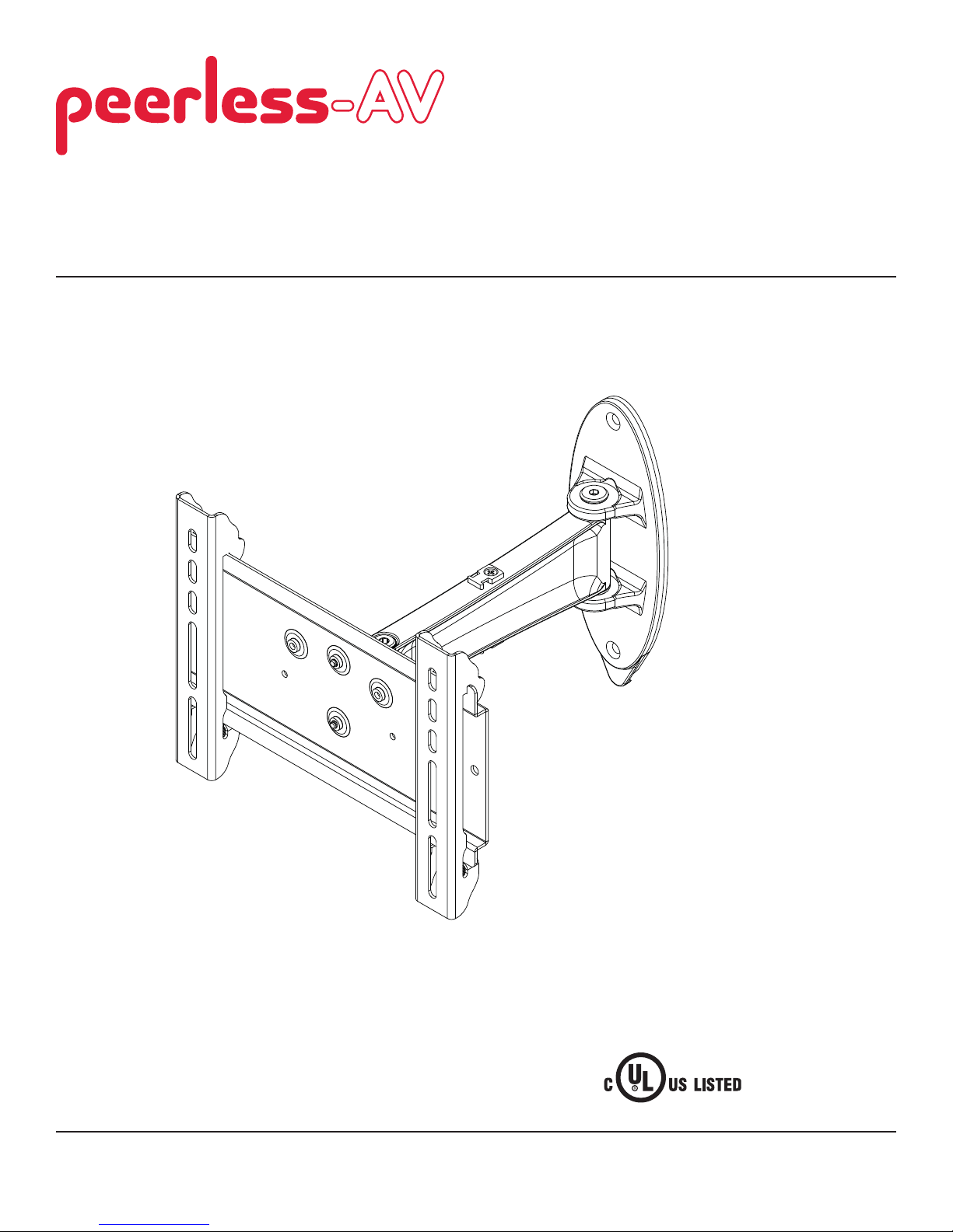
SmartMount™ Pivoting Wall Arm for 10" - 26" Flat Panel
Displays
Models: SP735P, SP735P-S
2300 White Oak Circle • Aurora, Il 60502 • (800) 865-2112 • Fax: (800) 359-6500 • www.peerlessmounts.com
Max UL Load Capacity: 25 lb (11.3 kg)
ISSUED: 02-15-10 SHEET #: 095-9316-2 08-02-11
Page 2

NOTE: Read entire instruction sheet before you start installation and assembly.
WARNING
• Do not begin to install your Peerless product until you have read and understood the instructions and warnings
contained in this Installation Sheet. If you have any questions regarding any of the instructions or warnings, for US
customers please call Peerless customer care at 1-800-865-2112, for all international customers, please contact
your local distributor.
• This product should only be installed by someone of good mechanical aptitude, has experience with basic building
construction, and fully understands these instructions.
• Make sure that the supporting surface will safely support the combined load of the equipment and all attached
hardware and components.
• Never exceed the Maximum UL Load Capacity. See page one.
• If mounting to wood wall studs, make sure that mounting screws are anchored into the center of the studs. Use of an
"edge to edge" stud fi nder is highly recommended.
• Always use an assistant or mechanical lifting equipment to safely lift and position equipment.
• Tighten screws fi rmly, but do not overtighten. Overtightening can damage the items, greatly reducing their holding
power.
• This product is intended for indoor use only. Use of this product outdoors could lead to product failure and personal
injury.
• This product was designed to be installed on the following wall construction only;
WALL CONSTRUCTION HARDWARE REQUIRED
• Wood Stud Included
• Wood Beam Included
• Solid Concrete Included
• Cinder Block Included
• Metal Stud Do not attach except with Peerless Metal Stud Accessory Kit
(not evaluated by UL)
• Brick Contact Qualifi ed Professional (not evaluated by UL)
• Other or unsure? Contact Qualifi ed Professional
Tools Needed for Assembly
• stud fi nder ("edge to edge" stud fi nder is recommended)
• phillips screwdriver
• drill
• 5/16" (8 mm) bit for concrete and cinder block wall
• 5/32" (4 mm) bit for wood stud wall
• level
Table of Contents
Parts List.................................................................................................................................................................................3
Wall Installation ................................................................................................................................................................. 4, 5
Installing Adapter Brackets .....................................................................................................................................................6
2 of 42
ISSUED: 02-15-10 SHEET #: 095-9316-2 08-02-11
Page 3
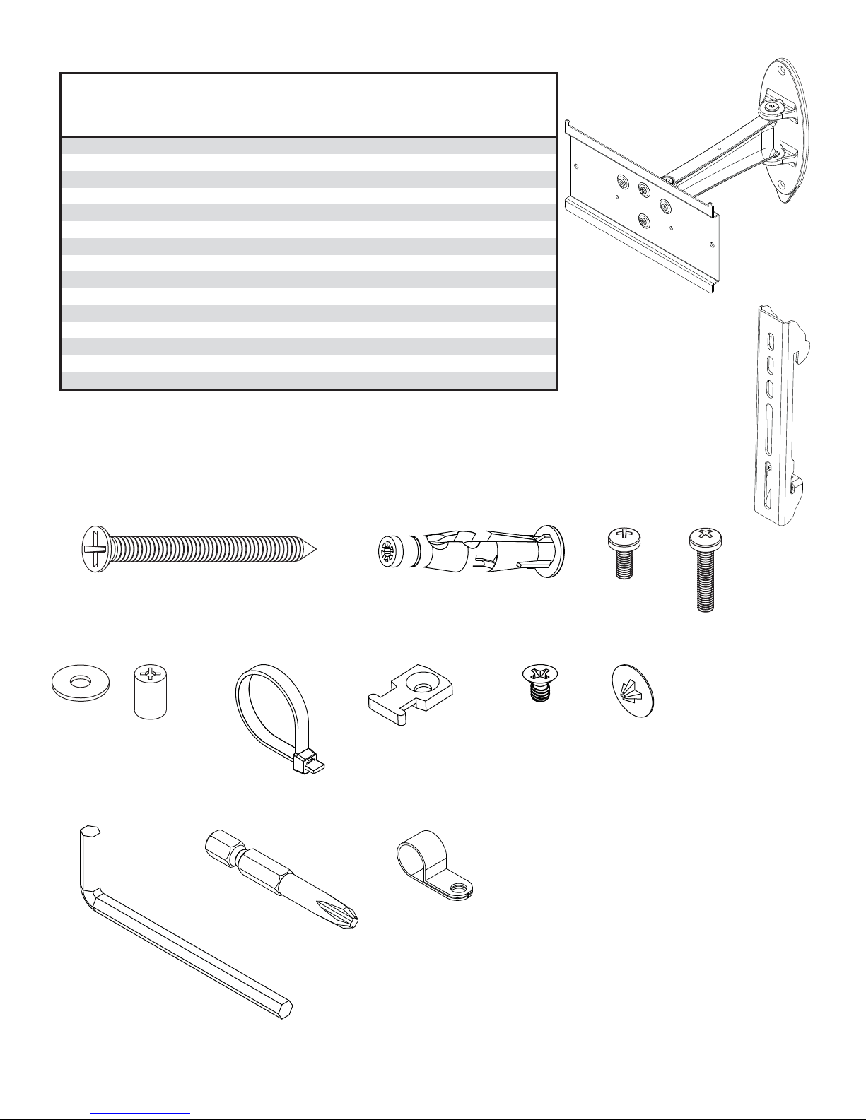
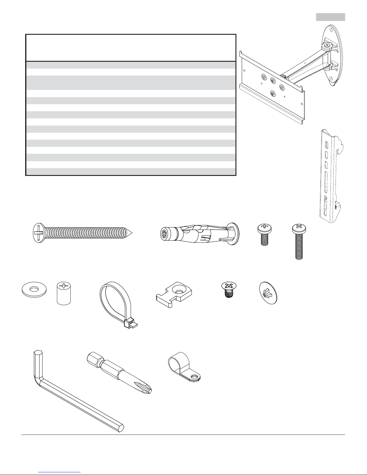
Before you begin, make sure all parts shown are included with your product.
A
Parts List
Description Qty. Part # Part #
A
wall arm assembly 1 095-P1965
B
adapter brackets 2 095-P1944
C
#14 x 2.5" flat head wood screw 2 520-1202
D
concrete anchor 2 590-0320
E
M4 x 12 mm phillips screw 4 504-9013
F
M4 x 20 mm phillips screw 4 504-9020
G
#10 flat washer 4 540-9400
H
retaining spacer 4 590-5005
I cable ties
J cable tie anchors
K 8-32 x 1/4" phillips screw
L screw cover
M 5 mm allen wrench
N #3 screwdriver bit
cable clip
O
Parts may appear slightly different than illustrated.
8
2
2
2
2
1
2
SP735P SP735P-S
095-4965
095-4644
520-2165
590-0320
504-2013
504-2014
540-9442
590-5003
560-1756 560-1756
590-1290 590-1290
520-1622 520-2622
590-1324 590-4324
560-9640 560-9640
560-0209 560-0209
590-1264 590-2164
B
C
M
G
H
N
D
IJ
O
E
F
K
L
3 of 42
ISSUED: 02-15-10 SHEET #: 095-9316-2 08-02-11
Page 4
Installation to Wood Stud Wall
WARNING
• Installer must verify that the supporting surface will safely support the combined load of the equipment and all
attached hardware and components.
• Tighten wood screws so that wall plate is fi rmly attached, but do not overtighten. Overtightening can damage the
screws, greatly reducing their holding power.
• Never tighten in excess of 80 in. • lb (9 N.M.).
• Make sure that mounting screws are anchored into the center of the stud. The use of an "edge to edge" stud fi nder is
highly recommended.
• Hardware provided is for attachment of mount through standard thickness drywall or plaster into wood studs.
Installers are responsible to provide hardware for other types of mounting situations (not evaluated by UL).
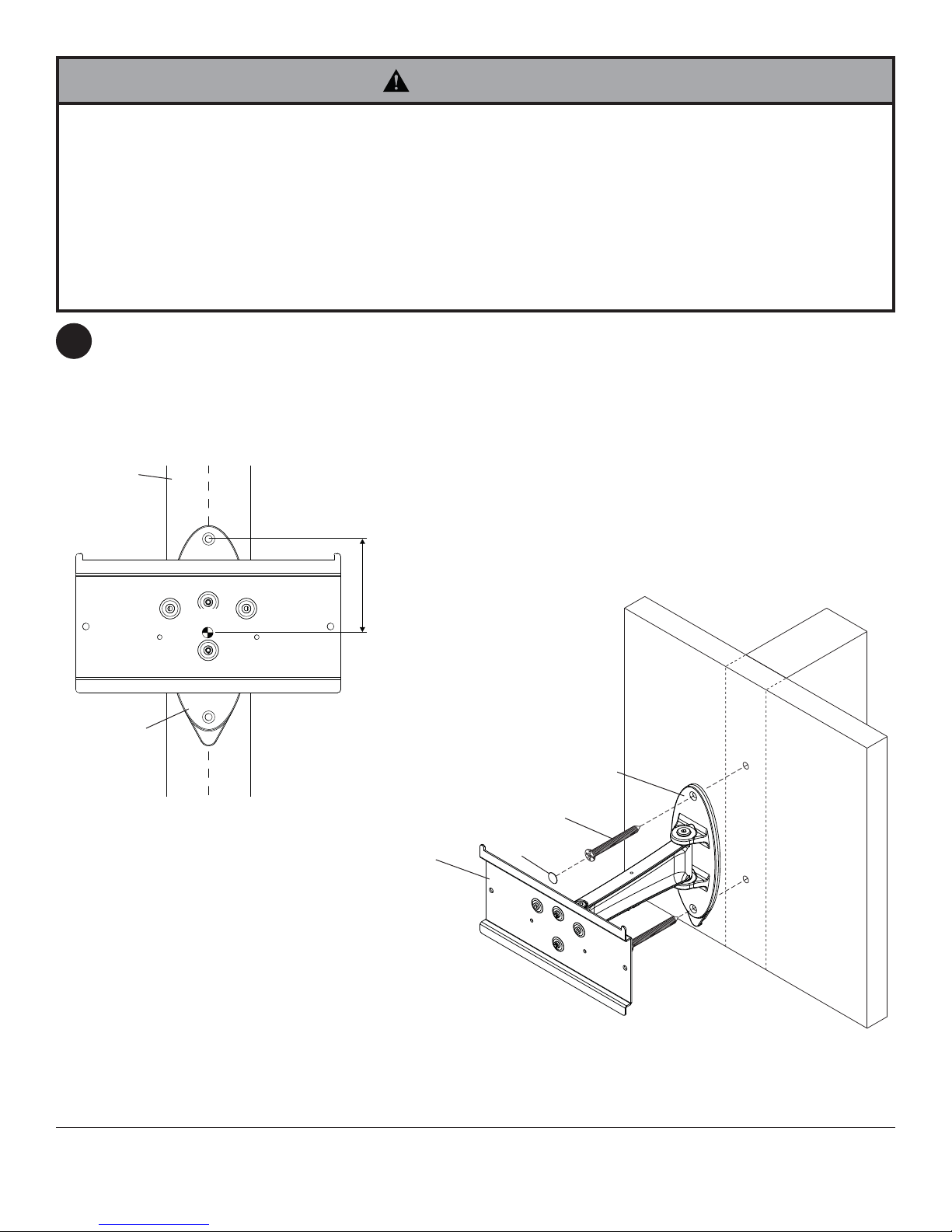
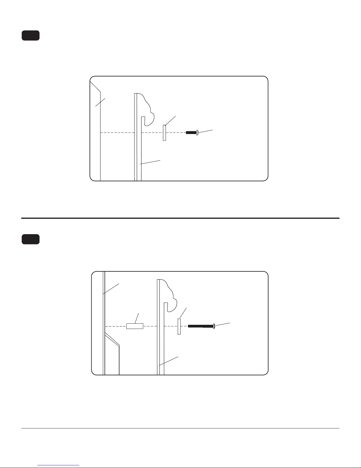
Use a stud fi nder to locate the edges of the studs. Based on their edges, draw a vertical line down each stud’s
1
center. Place wall plate (A) on wall as a template. The top mounting slots should be located 3.4" (86 mm)
above the desired display center as shown in fi gure 1.1. Level adapter plate (A), and mark the center of the two
mounting holes. Make sure that the mounting holes are on the stud centerlines. Drill two 5/32" (4 mm) dia. holes
2.5" (64 mm) deep. Make sure that the adapter plate is level, and secure it using four #14 x 2.5" wood screws (C)
as shown in fi g. 1.2.
Insert two screw covers (L) into screw heads.
STUD
DC
A
DC = DISPLAY CENTER
3.4"
(86 mm)
fi g. 1.1
WALL PLATE (A)
C
L
ADAPTER PLATE (A)
4 of 42
fi g. 1.2
ISSUED: 02-15-10 SHEET #: 095-9316-2 08-02-11
Page 5

Installation to Solid Concrete or Cinder Block
WARNING
• When installing Peerless wall mounts on cinder block, verify that you have a minimum of 1-3/8" (35 mm) of actual
concrete thickness in the hole to be used for the concrete anchors. Do not drill into mortar joints! Be sure to mount
in a solid part of the block, generally 1" (25 mm) minimum from the side of the block. Cinder block must meet ASTM
C-90 specifi cations. It is suggested that a standard electric drill on slow setting is used to drill the hole instead of a
hammer drill to avoid breaking out the back of the hole when entering a void or cavity.
• Concrete must be 2000 psi density minimum. Lighter density concrete may not hold concrete anchor.
• Make sure that the wall will safely support four times the combined load of the equipment and all attached hardware
and components.
Make sure that adapter plate (A) is level, use it
1
as a template to mark four mounting holes. The
top mounting slots should be located 3.4" (86
mm) above the desired display center as shown
in fi gure 1.1 on page 4. Drill two 5/16" (8 mm) dia.
holes to a minimum depth of 2.5" (64 mm). Insert
anchors (D) in holes fl ush with wall as shown
(right). Place wall plate (A) over anchors and
secure with two #14 x 2.5" screws (C). Level, then
tighten all fasteners.
Insert two screw covers (L) into screw heads.
WARNING
• Tighten screws so that wall plate is fi rmly attached,
but do not overtighten. Overtightening can damage
screws, greatly reducing their holding power.
• Never tighten in excess of 80 in. • lb (9 N.M.).
• Always attach concrete expansion anchors directly to
load-bearing concrete.
• Never attach concrete expansion anchors to concrete
covered with plaster, drywall, or other fi nishing
material. If mounting to concrete surfaces covered
with a fi nishing surface is unavoidable (not evaluated
by UL), the fi nishing surface must be counterbored
as shown below. Be sure concrete anchors do not
pull away from concrete when tightening screws. If
plaster/drywall is thicker than 5/8" (16 mm), custom
fasteners must be supplied by installer (not evaluated
by UL).
1
concrete
surface
D
Drill holes and insert anchors (D).
C
A
D
CINDER BLOCK
D
2
Place wall plate (A) over anchors (D) and secure with screws (C).
3
Tighten all fasteners.
SOLID CONCRETE
WALL PLATE (A)
INCORRECT CORRECT
wall
plate
plaster/
CUTAWAY VIEW
dry wall
concrete
wall
plate
plaster/
dry wall
concrete
5 of 42
C
L
ADAPTER PLATE (A)
ISSUED: 02-15-10 SHEET #: 095-9316-2 08-02-11
Page 6
Installing Adapter Brackets
WARNING
• Tighten screws so adapter brackets are fi rmly attached. Do not tighten with excessive force. Overtightening can
cause stress damage to screws, greatly reducing their holding power and possibly causing screw heads to become
detached. Tighten to 40 in. • lb (4.5 N.M.) maximum torque.
• If screws don't get three complete turns in the display inserts or if screws bottom out and bracket is still not tightly
secured, damage may occur to display or product may fail.
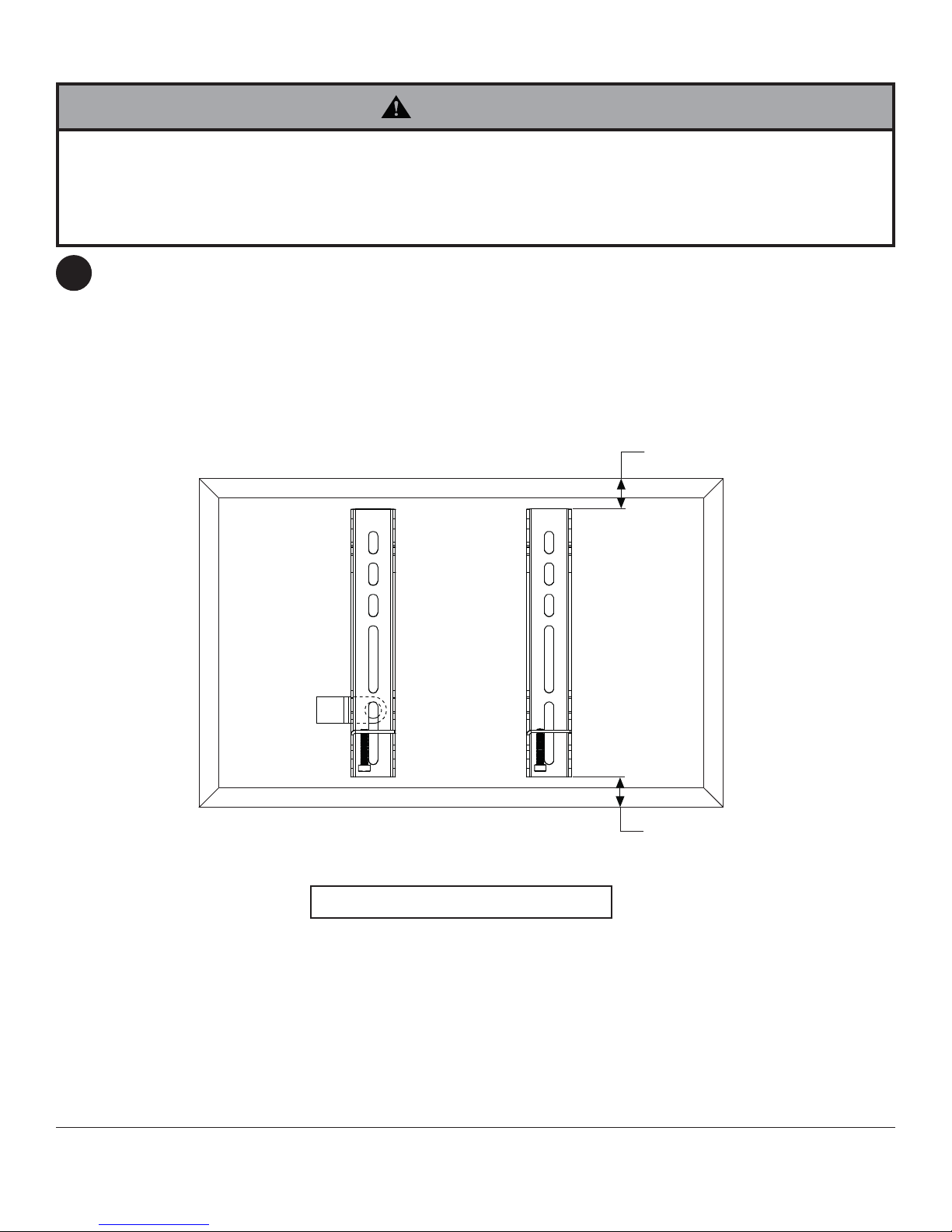
To prevent scratching the display, set a cloth on a fl at, level surface that will support the weight of the display.
2
Place display face side down. If display has knobs on the back, remove them to allow the adapter brackets to
be attached. Place adapter brackets (B) on back of display, align to holes, and center on back of display as
shown below. Attach the adapter brackets to the back of the display using the appropriate combination of screws,
washers, and spacers as shown in steps 2-1 or 2-2.
For cable management option, install cable clip (O) in between display and adapter brackets (B).
NOTE: Top and bottom holes must always be used.
Verify that all holes are properly aligned, and then tighten screws using a phillips screwdriver.
X
B
O
CENTER BRACKETS
VERTICALLY
ON BACK OF DISPLAY
NOTE: "X" dimensions should be equal.
NOTE: For fl at back displays proceed to step 2-1. For bump-out or recessed back display skip to step 2-2.
X
6 of 42
ISSUED: 02-15-10 SHEET #: 095-9316-2 08-02-11
Page 7
For Flat Back Display
Begin with the shortest length screw, hand thread through washer and adapter bracket into display as shown
2-1
below. Screw must make at least three full turns into the mounting hole and fi t snug into place. Do not over
tighten. If screw cannot make three full turns into the display, select a longer length screw from the baffl ed
fastener pack. Repeat for remaining mounting holes, level brackets and tighten screws.
NOTE: Spacers may not be used, depending upon the type of display.
If you have any questions, please call Peerless customer care at 1-800-865-2112.
DISPLAY
WASHER
SCREW
ADAPTER BRACKET (B)
For Bump-out or Recessed Back Display
Begin with longer length screw, hand thread through washer, adapter bracket and spacer in that order into display
2-2
as shown below. Screw must make at least three full turns into the mounting hole and fi t snug into place. Do not
over tighten. If screw cannot make three full turns into the display, select a longer length screw from the baffl ed
fastener pack. Repeat for remaining mounting holes, level brackets and tighten screws.
DISPLAY
SPACER
If you have any questions, please call Peerless customer care at 1-800-865-2112.
WASHER
SCREW
ADAPTER BRACKET (B)
7 of 42
ISSUED: 02-15-10 SHEET #: 095-9316-2 08-02-11
Page 8
Mounting and Removing Flat Panel Display
WARNING
• Always use an assistant or mechanical lifting equipment to safely lift and position the fl at panel displays.
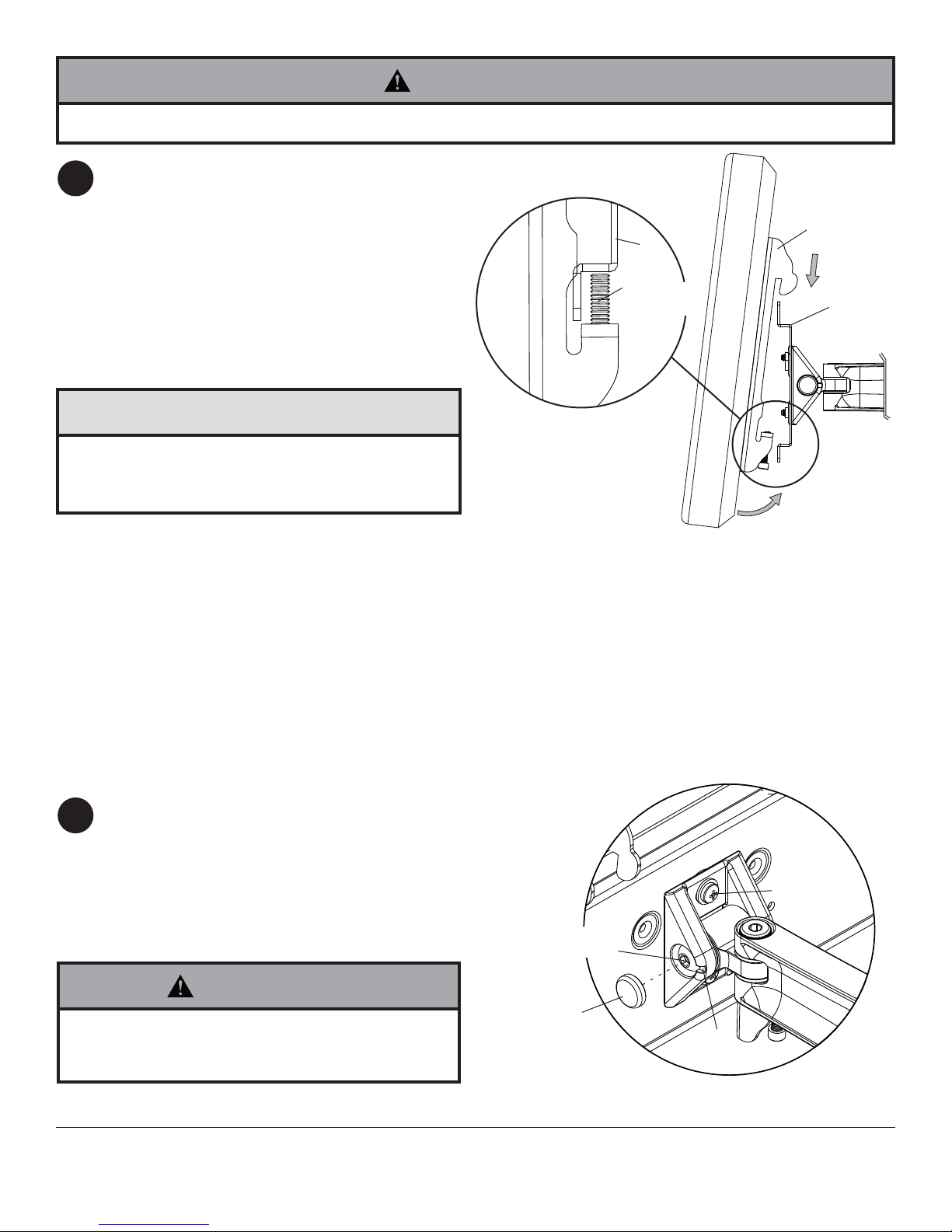
Hook adapter brackets (B) onto adapter plate (A).
3
Turn security screws, using phillips screwdriver,
clockwise at least six times to prevent display from
being removed as shown in cross section of fi g.
3.1.
NOTE: To lock the display down, tighten safety/
security screws to wall plate as shown in cross
section.
To remove display from mount, loosen safety/
security screws, swing display away from mount,
and lift display off of mount.
B
A
SECURITY
SCREWS
B
A
CAUTION
• Do not tighten screws with excessive force.
Overtightening can cause damage to mount. Tighten
screws to 40 in. • lb (4.5 N.M.) maximum torque.
If more or less tension is desired in tilt mechanism,
4
remove snap caps as shown in detail 1. Insert
a fl at head screwdriver into slot and pry cap
away from tilt mechanism. To adjust tilt, tighten
or loosen socket screw no more than half a turn
using 5 mm allen wrench (M).
To adjust roll (5° left or right), tighten or loosen
10-32 x 1/2" phillips screw.
CROSS SECTION
fi g 3.1
10-32 X 1/2"
SCREW
SOCKET
SCREW
WARNING
• If screws become loose over time, tighten screws
as necessary. Tighten screws to 50 in • lbs
(5.6 N.M.) maximum torque.
8 of 42
SNAP
CAP
SLOT
DETAIL 1
ISSUED: 02-15-10 SHEET #: 095-9316-2 08-02-11
Page 9
Cable Management
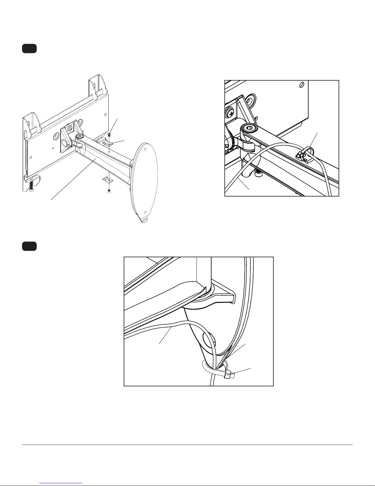
Cords may be routed using cable ties (I).
5-1
Attach cable tie anchor (J) to top or bottom of wall arm (A) using 8-32 x 1/4" phillips screw (K) as shown in
fi gure 5.1.
Secure cables to top or bottom of wall arm (A) using cable ties (I) as shown in fi gure 5.2.
K
I
J
CORD
WALL ARM (A)
5-2
Secure cables to bottom of wall plate using cable tie (I) as shown below.
fi g. 5.1
CABLE
fi g. 5.2
SLOT
I
9 of 42
ISSUED: 02-15-10 SHEET #: 095-9316-2 08-02-11
Page 10
Tension Adjustment
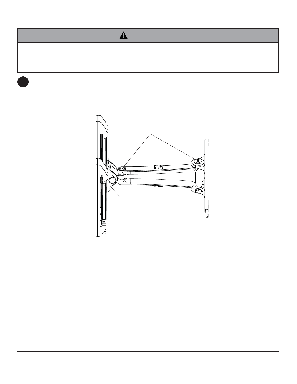
WARNING
• Do not remove screw or loosen screw until it is no longer engaged with the mount. Doing so may cause the display
to fall.
• If screws become loose over time, tighten screws as necessary. Tighten screws to 50 in. • lb (5.6 N.M.) maximum
torque.
If more or less tension is desired in the arm pivot points, do the following:
6
• To increase tension, turn tension screw(s) clockwise using 5 mm allen wrenchs (M). NOTE: Tighten screws to
50 in. • lb (5.6 N.M.) maximum torque.
• To reduce tension, turn tension screw(s) couter-clockwise using 5 mm allen wrenchs (M). NOTE: Do not
loosen more than half a turn.
TENSION SCREWS
A
10 of 42
All other brand and product names are trademarks or registered trademarks of their respective owners.
ISSUED: 02-15-10 SHEET #: 095-9316-2 08-02-11
© 2011, Peerless Industries, Inc. All rights reserved.
Peerless Industries, Inc.
2300 White Oak Circle
www.peerlessmounts.com
Aurora, Il 60502
Page 11

Instalación y montaje:
SmartMount™ Brazo de Pared Pivotantes para
pantalla plana de 10" a 26"
Modelos: SP735P, SP735P-S
2300 White Oak Circle • Aurora, Il 60502 • (800) 865-2112 • Fax: (800) 359-6500 • www.peerlessmounts.com
Capacidad máxima de soportar carga por UL: 25 lb (11.3 kg)
PUBLICADO: 02-15-10 HOJA #: 095-9316-2 08-02-11
Page 12
Español
NOTA: Lea la hoja de instrucciones completa antes de comenzar la instalación y el ensamblaje.
ADVERTENCIA
• No comience a instalar su producto de Peerless hasta haber leído y entendido las instrucciones y las advertencias
contenidas en la Hoja de Instalación. Si tiene alguna pregunta acerca de cualquiera de las instrucciones o las
advertencias, por favor, llame a Servicio al Cliente de Peerless al 1-800-865-2112 si está en EE. UU. Si es un cliente
internacional, por favor, comuníquese con su distribuidor local.
• Este producto sólo debe ser instalado por una persona que tenga una buena aptitud mecánica, que tenga
experiencia en construcción básica de edifi cios y que entienda estas instrucciones en su totalidad.
• Asegúrese de que la superfi cie de apoyo sostendrá, con seguridad, la carga combinada del equipo y todos los
fi jadores y componentes.
• Nunca sobrepase la capacidad máxima de soportar carga aceptada por Underwriters Laboratories. Vea la página 11.
• Si va a instalar el producto en una pared con montantes de madera, asegúrese de que los tornillos de montaje estén
anclados en el centro de los montantes. Se recomienda utilizar un localizador de montantes de "borde a borde".
• Siempre cuente con la ayuda de un asistente o utilice un equipo mecánico de izar para levantar y colocar el equipo
con más seguridad.
• Apriete los tornillos con fi rmeza, pero no en exceso. Apretarlos en exceso puede dañar los artículos y puede
disminuir signifi cativamente su fuerza de fi jación.
• Este producto está diseñado para uso en interiores solamente. Utilizar este producto en exteriores podría causar
fallas del producto y lesiones a individuos.
• Este producto fue diseñado para ser instalado en paredes con la siguiente construcción solamente:
CONSTRUCCIÓN DE LA PARED ACCESORIOS NECESARIOS
• Montante de madera Incluido
• Viga de madera Incluido
• Concreto macizo Incluido
• Bloque de hormigón de escorias Incluido
• Montante de metal No lo instale excepto con el juego de accesorios de Peerless para
montantes de metal (no
• Ladrillo Comuníquese con un profesional califi cado (no evaluados por UL)
• ¿Otra superfi cie o no está seguro? Comuníquese con un profesional califi cado
evaluados por UL)
Herramientas necesarias para el ensamblaje
• localizador de montantes (se recomienda uno de "borde a borde")
• destornillador phillips
• broca de 5/16" (8 mm) para paredes de concreto y de bloque de hormigón de escorias
• broca de 5/32" (4 mm) para paredes con montantes de madera
• nivel
Contenido
Lista de piezas..................................................................................................................................................................... 13
Instalación en una pared ............................................................................................................................................... 14, 15
Instalación de los soportes adaptadores ............................................................................................................................. 16
12 de 42
PUBLICADO: 02-15-10 HOJA #: 095-9316-2 08-02-11
Page 13
Antes de comenzar, asegúrese de que su producto incluye todas las piezas ilustradas.
Español
A
Lista de Piezas
Descripción Cant. N° de pieza N° de pieza
A
soporte de pared 1 095-P1965
B
soportes adaptadores 2 095-P1944
C tornillo de cabeza plana para madera
de #14 x 2-1/2"
D
anclajes de concreto 2 590-0320
E
tornillo phillips M4 x 12 mm 4 504-9013
F
tornillo phillips M4 x 20 mm 4 504-9020
G
N° 10 arandela 4 540-9400
H
espaciador de retención 4 590-5005
I Sujetacables
J Anclajes de los sujetacables
K tornillo phillips 8-32 x 1/4"
L Cubierta de los tornillos
M llave allend de 5 mm
N broca de #3
clip de fijación de cables
O
Las piezas podrían verse ligeramente diferentes a las ilustradas.
SP735P SP735P-S
2 520-1202 520-2165
560-1756 560-1756
8
590-1290 590-1290
2
520-1622 520-2622
2
590-1324 590-4324
2
560-9640 560-9640
2
560-0209 560-0209
1
590-1264 590-2164
2
095-4965
095-4644
590-0320
504-2013
504-2014
540-9442
590-5003
B
C
M
G
H
N
D
IJ
O
E
F
K
L
13 de 42
PUBLICADO: 02-15-10 HOJA #: 095-9316-2 08-02-11
Page 14

Español
Instalación en una pared con montantes de madera
ADVERTENCIA
• El instalador debe verifi car que la superfi cie de apoyo sea capaz de soportar fi rmemente la carga combinada del equipo y todos
los herrajes y componentes.
• Apriete los tornillos para madera de tal modo que la placa de apoyo quede fi rmemente sujeta, pero no apriete en exceso. El
apriete excesivo puede dañar los tornillos, reduciendo enormemente su fuerza de fi jación.
• Nunca apriete más de 80 pulg-lb (9 N•m).
• Asegúrese de que los tornillos de montaje queden bien fi jos en el centro del montante. Se recomienda usar un localizador de
montantes de "borde a borde".
• Los herrajes suministrados son para fi jar el soporte a través de tabique de yeso-cartón o yeso de espesor estándar a los
montantes de madera. Los instaladores son responsables de suministrar los herrajes para otros tipos de situaciones de montaje
(no evaluados por UL).
Utilizando un localizador de montantes, localice y marque los bordes del montante de madera utilizado para
1
instalar el producto. Utilice la placa de pared (A) como plantilla para marcar el centro de los agujeros sobre la
línea vertical. El agujero de montaje superior debe estar ubicado a 3.4" (86 mm) encima del punto donde quiere
que quede el centro de la pantalla, como se muestra en la fi gura 1.1. Taladre dos agujeros de 5/32" (4 mm) de
diámetro y 2.5" (64 mm) de profundidad. Fije el soporte de pared (A) a la pared utilizando dos tornillos para
madera de cabeza plana de 14 x 2.5" (C) como se muestra.
Inserte dos cubiertas de tornillos (L) en los cabezas de los tornillos.
MONTANTES
CP
A
CP = CENTRO DE LA PANTALLA
fi g. 1.1
SOPORTE DE PARED (A)
3.4"
(86 mm)
PLACA DE PARED (A)
C
L
14 de 42
fi g. 1.2
PUBLICADO: 02-15-10 HOJA #: 095-9316-2 08-02-11
Page 15

Instalación en una pared de concreto macizo o de bloques
Español
de hormigón de escorias
ADVERTENCIA
• Cuando instale soportes de pared Peerless en bloques de hormigón de escorias, verifi que que tengan un mínimo de 1-3/8"
(35 mm) de superfi cie efectiva de concreto en el agujero que va a utilizar para los anclajes de concreto. ¡No perfore en las
juntas de mortero! Asegúrese de instalar el soporte en una parte sólida del bloque, generalmente a un mínimo de 1" (25 mm) del
costado del bloque. El bloque de hormigón de escorias debe ser de conformidad con las especifi caciones C-90 de ASTM. Se
sugiere taladrar el agujero con un taladro eléctrico normal en velocidad lenta en vez de un taladro percutor para evitar romper la
parte trasera del agujero al entrar en un espacio o cavidad.
• El concreto debe tener una densidad mínima de 2000 psi. Un concreto menos denso podría no ser capaz de sujetar el anclaje
para concreto.
• El instalador debe verifi car que la superfi cie de apoyo sea capaz de soportar fi rmemente la carga combinada del equipo y todos
los herrajes y componentes.
Utilice la placa de pared como plantilla para marcar
1
el centro de los agujeros. El agujero de montaje
superior debe estar ubicado a 3.4" (86 mm) encima
del punto donde quiere que quede el centro de la
pantalla, como se muestra en la fi gura 1.1, de la
página 14. Taladre dos agujeros de 5/16" (8 mm)
de diámetro a una profundidad mínima de 2.5"
(64 mm). Inserte los anclajes (D) en los agujeros.
Coloque el soporte de pared (A) sobre los anclajes
y fi je el soporte de pared en la pared utilizando dos
tornillos para madera de cabeza plana de
14 x 2.5" (C).
Inserte dos cubiertas de tornillos (L) en los cabezas
de los tornillos.
ADVERTENCIA
• Apriete los tornillos de tal modo que la placa de apoyo
quede fi rmemente sujeta, pero no los apriete en exceso.
El apriete excesivo puede dañar los tornillos, reduciendo
enormemente su fuerza de fi jación.
• Nunca apriete más de 80 pulg-lb (9 N•m).
• Siempre fi je los anclajes de expansión directamente al
concreto que soporta carga.
• Nunca fi je los anclajes de expansión a una pared de
concreto recubierta con yeso, tabiques de yeso-cartón u
otro material de acabado. Si el montaje a superfi cies de
concreto recubiertas con una superfi cie de acabado es
inevitable (no evaluados por UL), será necesario escariar
el acabado, como se muestra más abajo. Asegúrese de
que los anclajes de concreto no se alejen del concreto al
apretar los tornillos. Si el grosor de la pared de yeso/tabique
de yeso-cartón es mayor que 5/8" (16 mm), el instalador
deberá suministrar fi jaciones especiales (no evaluados por
UL).
INCORRECTO
CORRECTO
1
Taladre los agujeros y inserte los anclajes (D).
2
Coloque la placa de pared (A) sobre el anclaje (D) y fíjela con el
tornillo (C).
3
Apriete todos los sujetadores.
CONCRETO MACIZO
PLACA DE PARED (A)
C
L
C
pared de
concreto
D
A
D
BLOQUE DE HOR-
MIGÓN DE ESCORIAS
D
placa
de
pared
VISTA EN CORTE
concreto
yeso / tabique de yeso-cartón
placa
pared
de
concreto
15 de 42
SOPORTE DE PARED (A)
PUBLICADO: 02-15-10 HOJA #: 095-9316-2 08-02-11
Page 16

Español
Instalación de los soportes adaptadores
ADVERTENCIA
• Apriete los tornillos de tal modo que los soportes adaptadores queden fi rmemente sujetos. No apriete aplicando
demasiada fuerza. El apriete excesivo puede causar daño por esfuerzo a los tornillos, reduciendo enormemente su
fuerza de fi jación y causando el posible desprendimiento de sus cabezas. Apriete los tornillos a 40 pulg-lb (4.5 N•m)
de par torsor máximo.
• Si los tornillos no pueden atornillarse con tres vueltas completas en los insertos de la pantalla, o si los tornillos topan
fondo y la placa todavía no está fi rmemente sujeta, se podría dañar la pantalla o causar la falla del producto.
Para no rayar la pantalla, coloque un trapo sobre una superfi cie plana y nivelada que sostenga el peso de la
2
pantalla. Coloque la pantalla boca abajo. Si la pantalla tiene perillas en la parte trasera, quíteselas para poder
fi jar los soportes adaptadores. Coloque los soportes adaptadores (B) en la parte trasera de la pantalla, alinéelos
con los agujeros y centralícelos en la parte trasera de la pantalla, como se muestra abajo. Fije los soportes
adaptadores en la parte trasera de la pantalla utilizando la combinación adecuada de tornillos, arandelas y
espaciadores, como se muestra en la paso 2-1 o en la pasp 2-2.
Para contar con la opción para el manejo de cables, instale el clip de fi jación de cables (O) entre la pantalla y los
soportes adaptadores (B).
NOTA: Siempre se tienen que usar los agujeros superiores y los inferiores.
Verifi que que todos los agujeros estén debidamente alineados y luego apriete los tornillos usando un destornillador
phillips.
O
B
CENTRALICE LOS
SOPORTES
VERTICALMENTE EN LA
PARTE TRASERA DE LA
PANTALLA
X
X
NOTA: Las dimensiones "X" deben ser iguales.
NOTA: En el caso de los televisores que tienen la parte posterior plana, pase al paso 2-1. En el caso de los televisores
que tienen la parte posterior abultada o empotrada, pase al paso 2-2.
16 de 42
PUBLICADO: 02-15-10 HOJA #: 095-9316-2 08-02-11
Page 17

Instalación de un televisor que tiene la parte posterior plana
Comience con uno de los tornillos más cortos, enrósquelo, con la mano, a través de la arandela y el soporte
2-1
adaptador a la parte posterior de la pantalla, como se muestra abajo. El tornillo debe dar, por lo menos, tres
vueltas completas dentro del agujero de instalación y debe quedar ajustado en su lugar. No apriete los tornillos en
exceso. Si el tornillo no puede dar tres vueltas completas al entrar en la parte posterior de la pantalla, seleccione
un tornillo más largo de los sujetadores identifi cados y clasifi cados en las divisiones del empaque plástico. Siga el
mismo procedimiento con los agujeros de instalación restantes, nivele los soportes y apriete los tornillos.
NOTA: Es posible que no necesite usar los espaciadores, dependiendo del tipo de pantalla.
PANTALLA
ARANDELA
TORNILLO
SOPORTE
ADAPTADOR (B)
Español
Si tiene alguna pregunta, por favor, llame a servicio al cliente de Peerless al 1-800-865-2112.
Instalación de un televisor que tiene la parte posterior abultada o empotrada
Comience con uno de los tornillos más largos, enrósquelo, con la mano, a través de la arandela, el soporte
2-2
adaptador y el espaciador, en ese orden, a la parte posterior de la pantalla, como se muestra abajo. El tornillo
debe dar, por lo menos, tres vueltas completas dentro del agujero de instalación y debe quedar ajustado en su
lugar. No apriete los tornillos en exceso. Si el tornillo no puede dar tres vueltas completas al entrar en la parte
posterior de la pantalla, seleccione un tornillo más largo de los sujetadores identifi cados y clasifi cados en las
divisiones del empaque plástico. Siga el mismo procedimiento con los agujeros de instalación restantes, nivele los
soportes y apriete los tornillos.
PANTALLA
ESPACIADOR
ARANDELA
TORNILLO
Si tiene alguna pregunta, por favor, llame a servicio al cliente de Peerless al
17 de 42
SOPORTE
ADAPTADOR (B)
1-800-865-2112.
PUBLICADO: 02-15-10 HOJA #: 095-9316-2 08-02-11
Page 18

Montaje y desmontaje de la pantalla plana
ADVERTENCIA
• Siempre cuente con un asistente o con un equipo mecánico de izar para levantar y colocar los televisores de
pantalla plana con más seguridad.
Enganche los soportes adaptadores (B) en la
3
soporte de pared (A). Déles, por lo menos, seis
vueltas a los tornillos de seguridad en el sentido
del movimiento de las manecillas del reloj con una
destornillador phillips para evitar que se pueda
quitar la pantalla, como se muestra en la sección
transversal de la fi gura 3.1.
NOTA: Para trabar la pantalla, apriete los tornillos
de seguridad a la placa de pared, como se muestra
en la sección transversal.
Para quitar la pantalla del soporte, afl oje los tornillos
de seguridad, gire la pantalla retirándola del soporte
y levántela para sacarla del soporte.
B
SECCIÓN
TRANSVERSAL
A
TORNILLOS
DE
SEGURIDAD
Español
B
A
fi g 3.1
ATENCIÓN
• No apriete los tornillos aplicando demasiada fuerza.
El apriete excesivo podría dañar el soporte. Apriete
los tornillos a 40 pulg-lb (4.5 N•m) de par torsor
máximo.
Si se desea mayor o menor tensión en el
4
mecanismo de inclinación, quite las tapas de
presión como se muestra en el detalle 1. Inserte un
desarmador de punta plana en la ranura y levante
y retire la tapa del mecanismo de inclinación. Para
ajustar la inclinación, simplemente apriete o afl oje
los tornillos de cabeza hueca no más de media
vuelta usando una llave allen 5 mm (M).
Para ajustar el giro (+/- 5°), simplemente apriete o
afl oje la tornillo del número 10-32.
TORNILLO
10-32 X 1/2"
TORNILLO DE
CABEZA HUECA
ADVERTENCIA
• Si los tornillos se afl ojan con el tiempo, apriételos
según sea necesario. Apriete los tornillos a un
máximo de 50 pulg-lb (5.6 N•m) de par torsor.
18 de 42
TAPAS DE
PRESIÓN
RANURA
DETALLE 1
PUBLICADO: 02-15-10 HOJA #: 095-9316-2 08-02-11
Page 19

Manejo de cables
Los cables se pueden acomodar utilizando los sujetacables (I).
5-1
Fije el anclaje del sujetacables (J) a la parte superior o inferior del brazo de pared (A) utilizando un tornillo phillips
de 8-32 x 1/4" (K), como se muestra en la fi gura 5.1.
Fije los cables a la parte superior o inferior del brazo de pared (A) utilizando los sujetacables (I), como se muestra
en la fi gura 5.2.
Español
K
I
J
CABLES
BRAZO DE PARED (A)
5-2
También, puede fi jar los cables en la ranura de la parte inferior de la placa de pared utilizando un sujetacables (I),
como se muestra abajo.
fi g. 5.1
CABLES
fi g. 5.2
RANURA
I
19 de 42
PUBLICADO: 02-15-10 HOJA #: 095-9316-2 08-02-11
Page 20

Ajuste Tensor del Brazo
ADVERTENCIA
• No retire el tornillo ni lo afl oje hasta que se haya desenganchado del soporte. Se podría caer la pantalla.
• Si los tornillos se afl ojan con el tiempo, apriételos según sea necesario. Apriete los tornillos a un máximo de
50 pulg-lb (5.6 N•m) de par torsor.
Si desea aumentar o disminuir la tensión en los puntos de articulación del brazo, haga lo siguiente:
6
• Para aumentarla, gire el tornillo de cabeza hueca en sentido horario con la llave allen de 5 mm (M).
NOTA: Apriete los tornillos a un máximo de 40 pulg-lb (4.5 N•m) de par torsor.
• Para reducirla, gire el tornillo de cabeza hueca en sentido contrahorario con la llave allen de 5 mm (M).
NOTA: No lo gire más de media vuelta.
TORNILLOS TENSORES
Español
A
20 de 42
Cualesquiera otras marcas y nombres de productos son marcas comerciales o registradas de sus respectivos dueños.
PUBLICADO: 02-15-10 HOJA #: 095-9316-2 08-02-11
© 2011, Peerless Industries, Inc. Todos los derechos reservados.
Peerless Industries, Inc.
2300 White Oak Circle
Aurora, Il 60502
www.peerlessmounts.com
Page 21

Installation et assemblage :
SmartMount™ Bras mural Pivotement Pour Écran à plat
de 10 à 26 po
Modèles : SP735P, SP735P-S
2300 White Oak Circle • Aurora, Il 60502 • (800) 865-2112 • Fax: (800) 359-6500 • www.peerlessmounts.com
Capacité de charge maximale par l’UL établie: 25 lb (11.3 kg)
PUBLIÉ LE : 02-15-10 FEUILLE no : 095-9316-2 08-02-11
Page 22

Français
REMARQUE: lisez entièrement la fi che d’instructions avant de commencer l’installation et l’assemblage.
AVERTISSEMENT
• Ne commencez pas à installer votre produit Peerless avant d’avoir lu et assimilé les instructions et les avertissements
contenus dans cette fi che d’installation. Pour toute question concernant les instructions ou les avertissements,
veuillez appeler le service à la clientèle de Peerless au 1-800-865-2112; tous les clients internationaux sont priés de
contacter leur distributeur local.
• Ce produit doit être installé uniquement par quelqu’un possédant une bonne aptitude à la mécanique, une expérience
de la construction immobilière et ayant bien compris ces instructions.
• Assurez-vous que la surface de support puisse soutenir sans danger la charge totale de l’équipement ainsi que des
pièces et composants qui y sont attachés.
• Ne dépassez jamais la capacité de charge maximum établie par l’UL. Reportez-vous à la page 21.
• Lors d’une installation sur un mur à montants en bois, assurez-vous que les vis de montage sont ancrées au centre
des montants. L’utilisation d’un localisateur de montants « bord à bord » est fortement recommandée.
• Pour lever et positionner l’équipement en toute sécurité, faites-vous toujours aider par une autre personne ou utilisez
un dispositif de levage mécanique.
• Serrez fermement les vis, mais sans excès. Un serrage excessif peut endommager les composants et en réduire
considérablement la capacité de support.
• Ce produit est conçu uniquement pour un usage intérieur. L’utilisation de ce produit à l’extérieur peut causer une
défaillance du produit et des blessures corporelles.
• Ce produit a été conçu uniquement pour une installation sur les types de murs ci-dessous :
TYPE DE MUR PIÈCES DE FIXATION REQUISES
• Montant en bois Incluses
• Poutre en bois Incluses
• Béton plein Incluses
• Bloc de béton de mâchefer Incluses
• Montant métallique Ne pas installer sur ce type de mur sauf à l’aide de l’ensemble d’accessoires
Peerless pour montants métalliques (non évalué UL)
• Brique Contacter un professionnel qualifi é (non évalué UL)
• Autre, ou vous n’êtes pas sûr ? Contacter un professionnel qualifi é
Outils nécessaires au montage
• localisateur de montants (un localisateur de montants « bord à bord » est recommandé)
• tournevis phillips
• foret de 5/32 po (4 mm) pour les murs à montants en bois
• foret de 5/16 po (8 mm) pour les murs à block de béton
• niveau
Tabla de contenido
Lista de piezas......................................................................................................................................................................23
Installation sur un mur ....................................................................................................................................................24, 25
Installation des supports adaptateurs ...................................................................................................................................26
22 sur 42
PUBLIÉ LE : 02-15-10 FEUILLE no : 095-9316-2 08-02-11
Page 23

Avant de commencer, assurez-vous que toutes les pièces indiquées sont incluses avec le produit.
Français
A
Liste des Pièces
Description Qté. Nº de pièce Nº de pièce
A
support mural 1 095-P1965
B
supports adaptateurs 2 095-P1944
C
vis à bois à tête plate nº14 x 2,5 po 2 520-1202
D
chevilles d’ancrage 2 590-0320
E
Vis cruciforme M4 x 12 mm 4 504-9013
F
Vis cruciforme M4 x 20 mm 4 504-9020
G
N° 10 rondelle 4 540-9400
H
entretoise de retenue 4 590-5005
I Attaches de câble
J Ancrages des attaches de câble
K Vis cruciforme 8-32 x 1/4"
L Cache-vis
M hexagonale de 5 mm
N Foret de #3
bride de cordons additionnelle
O
Il est possible que les pièces semblent légèrement différentes de celles illustrées ici.
SP735P SP735P-S
560-1756 560-1756
8
590-1290 590-1290
2
520-1622 520-2622
2
590-1324 590-4324
2
560-9640 560-9640
2
560-0209 560-0209
1
590-1264 590-2164
2
095-4965
095-4644
520-2165
590-0320
504-2013
504-2014
540-9442
590-5003
B
C
M
G
H
N
D
IJ
O
E
F
K
L
23 sur 42
PUBLIÉ LE : 02-15-10 FEUILLE no : 095-9316-2 08-02-11
Page 24

Français
Installation sur un mur à montant en bois
AVERTISSEMENT
• L’installateur doit s’assurer que la surface de support pourra soutenir sans danger la charge combinée de
l’équipement, de toute sa visserie et de tous ses composants.
• Serrez les vis à bois de manière que la plaque murale soit fermement fi xée, mais sans excès. Un serrage excessif
peut endommager les vis et en réduire considérablement le pouvoir de maintien.
• Ne serrez jamais à plus de 9 Nm (80 po-lb).
• Assurez-vous que les vis de montage sont ancrées au centre des montants. L’usage d’un localisateur de montants
« bord à bord » est fortement conseillé.
• La visserie est fournie pour fi xer la monture à travers une cloison sèche ou du plâtre d’épaisseur standard et dans
des montants en bois. Il appartient aux installateurs de fournir la visserie nécessaire pour d’autres types de situations
(non évalué UL).
À l’aide d’un localisateur de montants, repérez et marquez les bords des montants en bois utilisés pour monter
1
ce produit. Utilisez un niveau pour tracer une ligne verticale le long du centre du montant. Le trou de montage
supérieur doit être situé à
à la fi gure 1.1. Percez deux trous de 4 mm (5/32 po) de diamètre et de 64 mm (2,5 po) de profondeur. Fixez le bras
mural (A) sur le mur à l’aide de deux vis à bois à tête plate nº14 x 2,5 po (C), comme illustré.
Insérez deux cache-vis (L) dans les têtes de vis.
MONTANT
3,4 po (86 mm) au-dessus de l’endroit souhaité pour le centre de l’écran comme illustré
CE
A
CE = LE CENTRE DE L’ÉCRAN
PLAQUE ADAPTATEUR (A)
3.4"
(86 mm)
fi g. 1.1
PLAQUE MURALE (A)
C
L
24 sur 42
fi g. 1.2
PUBLIÉ LE : 02-15-10 FEUILLE no : 095-9316-2 08-02-11
Page 25

Français
Installation sur du béton plein ou un bloc de béton de mâchefer
AVERTISSEMENT
• Si vous installez des montures murales Peerless sur un bloc de béton de mâchefer, vérifi ez que vous disposez d’une
épaisseur de béton d’au moins 35 mm (1 3/8 po) dans le trou destiné aux ancrages de béton. Ne percez pas dans
les joints de mortier ! Veillez à effectuer le montage dans une partie pleine du bloc, généralement à au moins 25 mm
(1 po) du côté du bloc. Le bloc de béton de mâchefer doit être conforme aux spécifi cations de l’ASTM C-90. Pour
percer le trou, il est conseillé d’utiliser une perceuse électrique standard sur un réglage bas au lieu d’un marteau
perforateur, afi n d’éviter de briser la partie arrière du trou lorsque vous pénétrez un vide ou une cavité.
• Le béton doit avoir une densité minimum de 2 000 psi. Un béton de densité moindre risquerait de ne pas retenir un
ancrage de béton.
• Assurez-vous que la surface de support pourra soutenir sans danger la charge combinée de l’équipement, de toute
sa visserie et de tous ses composants.
Utilisez la plaque murale comme gabarit pour
1
marquer le centre des trous. Le trou de montage
supérieur doit être situé à 3,4 po (86 mm) au-dessus
de l’endroit souhaité pour le centre de l’écran comme
illustré à la fi gure 1.1 en page 24. Percez deux trous
de 5/16 po (8 mm) de dia. à une profondeur minimale
de 2,5 po (64 mm). Insérez les chevilles d’ancrage
(D) dans les trous. Posez le support mural (A) sur les
chevilles d'ancrage et fi xez-le au mur à l'aide de deux
vis à bois à tête plate no 14 x 2,5 po (C).
Insérez deux cache-vis (L) dans les têtes de vis.
AVERTISSEMENT
• Serrez les vis de manière que la plaque murale
soit fermement fi xée, mais sans excès. Un serrage
excessif peut endommager les vis et en réduire
considérablement le pouvoir de maintien.
• Ne serrez jamais à plus de 9 Nm (80 po-lb).
• Fixez toujours des ancrages de béton directement sur
du béton porteur.
• Ne fi xez jamais d’ancrages sur du béton recouvert de
plâtre, une cloison sèche ou autre matériau de fi nition.
Si vous ne pouvez pas éviter d’effectuer le montage
sur du béton recouvert d’une surface de fi nition,
celle-ci doit être chambrée (non évalué UL), comme
indiqué cidessous. Assurez-vous que les ancrages
de béton ne se séparent pas du béton lorsque vous
serrez les vis. Si l’épaisseur du plâtre / de la cloison
sèche dépasse 16 mm (5/8 po), des fi xations adaptées
devront être fournies par l’installateur (non évalué UL).
INCORRECT CORRECT
1
Percez les trous et insérez les chevilles d’ancrage (D).
2
Posez la plaque murale (A) sur l’ancrage (D) et fi xez-la à l’aide
d’une vis (C).
3
Serrez toutes les fi xations.
BÉTON PLEIN
PLAQUE MURALE (A)
C
L
C
béton plein
D
A
D
BLOC DE BÉTON
DE MÂCHEFER
D
béton
plaque
mural
plâtre /
VUE EN COUPE
cloison sèche
plaque
mural
plâtre /
cloison sèche
béton
25 sur 42
PLAQUE ADAPTATEUR (A)
PUBLIÉ LE : 02-15-10 FEUILLE no : 095-9316-2 08-02-11
Page 26

Français
Installation des supports adaptateurs
AVERTISSEMENT
• Serrez les vis de manière à fi xer solidement les supports adaptateurs. N’employez pas une force excessive pour ce
faire. Un serrage excessif peut causer des contraintes risquant d’endommager les vis, de réduire considérablement
leur pouvoir de maintien et d’en détacher les têtes. Serrez les vis à un couple maximum de 4,5 Nm (40 po-lb).
• Si les vis ne sont pas enfoncées de trois tours complets dans les inserts ou si elles sont serrées au maximum sans
parvenir à maintenir solidement le support, l’écran peut être abîmé ou le produit détérioré.
Afi n d’éviter de rayer l’écran, posez un morceau de tissu sur une surface plane et de niveau qui peut supporter le
2
poids de l’écran. Déposez l’écran à plat, tourné vers le bas. Si l’écran possède des boutons à l’arrière, enlevez-les
pour pouvoir attacher les supports adaptateurs. Placez les supports adaptateurs (B) à l’arrière de l’écran, alignezles sur les trous et centrez-les sur l’arrière de l’écran, comme illustré ci-dessous. Fixez les supports adaptateurs à
l’arrière de l’écran à l’aide des vis, rondelles et entretoises appropriées, comme illustré sur en l’étape 2-1 ou 2-2.
Pour l'option de gestion des câbles, installez l'bride de cordons additionnelle (O) entre l'écran et supports
adaptateurs (B).
REMARQUE: Les trous supérieurs et inférieurs de l’écran doivent toujours être utilisés.
Veillez à ce que tous les trous soient bien alignés, puis serrez les vis à l’aide d’une tournevis phillips.
X
B
O
CENTREZ LES
SUPPORTS À LA
VERTICALE À
L’ARRIÈRE DE L’ÉCRAN
REMARQUE: les dimensions de « X » doivent être égales.
REMARQUE: Pour les écrans à dos plat, exécutez l’étape 2-1. Pour les écrans à dos convexes ou concaves, passez
à l’étape 2-2.
X
26 sur 42
PUBLIÉ LE : 02-15-10 FEUILLE no : 095-9316-2 08-02-11
Page 27

Pour les écrans à dos plat
Commencez par la vis la plus courte et vissez-la manuellement à l’écran en la faisant passer à travers la rondelle
2-1
et le support adaptateur, comme indiqué ci-dessous. La vis doit effectuer au moins trois tours complets dans le
trou de fi xation et tenir solidement en place. Ne pas trop serrer. S’il est impossible d’effectuer trois tours de vis
complets, choisissez une vis plus longue dans le jeu de fi xations à compartiments. Répétez pour le reste des trous
de fi xation, mettez les supports à niveau et resserrez les vis.
REMARQUE: Il n’est pas toujours nécessaire d’utiliser des entretoises, selon le type d’écran.
Français
ÉCRAN
RONDELLE
VIS
SUPPORT
ADAPTATEUR (B)
Pour toute question, veuillez appeler le service à la clientèle de Peerless au 1-800-865-2112.
Pour un écran à dos convexe ou concave
Commencez par la vis la plus longue et vissez-la manuellement à l’écran en la faisant passer à travers la
2-2
rondelle, le support adaptateur et l’entretoise comme indiqué ci-dessous. La vis doit effectuer au moins trois tours
complets dans le trou de fi xation et tenir solidement en place. Ne pas trop serrer. S’il est impossible d’effectuer
trois tours de vis complets, choisissez une vis plus longue dans le jeu de fi xations à compartiments. Répétez pour
le reste des trous de fi xation, mettez les supports à niveau et resserrez les vis.
ÉCRAN
ENTRETOISE
RONDELLE
VIS
Pour toute question, veuillez appeler le service à la clientèle de Peerless au 1-800-865-2112.
SUPPORT
ADAPTATEUR (B)
27 sur 42
PUBLIÉ LE : 02-15-10 FEUILLE no : 095-9316-2 08-02-11
Page 28

Montage et demontage d'un écran plat
AVERTISSEMENT
• Pour lever et positionner l’écran plasma en toute sécurité, faites-vous toujours aider par une autre personne ou
utilisez un matériel de levage mécanique.
Accrochez les supports adaptateurs (B) à le bras
3
mural
(A). Tournez les vis de sûreté/sécurité à
l’aide tournevis phillips au moins six fois dans le
sens horaire pour éviter le retrait de l’écran comme
illustré dans la coupe transversale de la fi g. 3.1.
REMARQUE : Pour verrouiller l’écran vers le bas,
serrez les vis se sûreté/sécurité à la plaque murale
comme illustré dans la coupe transversale. Pour
retirer l’écran du support, desserrez les vis de
sûreté/sécurité, faites pivoter l’écran hors du support
et soulevez-le.
ATTENTION
B
COUPE
TRANSVERSALE
A
B
VIS DE
SÛRETÉ/
SÉCURITÉ
Français
A
fi g 3.1
• N’employez pas une force excessive pour serrer
les vis. Un serrage excessif peut endommager la
monture. Serrez les vis à un couple maximum de
4,5 Nm (40 po-lb).
Si vous souhaitez augmenter ou diminuer la tension
4
du mécanisme d’inclinaison, enlevez les capuchons
encliquetables comme illustré sur le détail 1. Insérez
un tournevis à tête plate dans la fente et sortez le
capuchon du mécanisme d’inclinaison. Pour régler
l’inclinaison, il suffi t de serrer ou de desserrer la vis
à tête creuse d’un maximum d’un demi-tour à l’aide
d’une clé hexagonale de 5 mm (M).
Pour régler le roulis(+/- 5°), il suffi t de serrer ou de
desserrer l’viz Nylock 10-32.
VIZ 10-32 X 1/2"
VIS À TÊTE
CREUSE
AVERTISSEMENT
• Si les vis se desserrent au fi l du temps, resserrezles au besoin. Serrez les vis à un couple maximal
de 50 po-lb (5,6 Nm).
CAPUCHONS
ENCLIQUETABLES
28 sur 42
FENTE
DÉTAIL 1
PUBLIÉ LE : 02-15-10 FEUILLE no : 095-9316-2 08-02-11
Page 29

Gestion des câbles
Les câbles peuvent être acheminés à l'aide d'attaches de câble (I).
5-1
Fixez l' ancrage des attaches de câble (J) au haut ou au bas du bras mural (A) à l'aide d'une vis Phillips 8-32 x 1/4
(K) comme illustré à la fi gure 5.1.
Attachez les câbles au haut ou au bas du bras mural (A) à l'aide d'attaches de câble (I) comme illustré à la fi gure
5.2.
Français
K
I
J
BRAS MURAL (A)
5-2
Les câbles peuvent également être attachés à la fente située au bas de la plaque murale à l'aide d'une attache de
câble (I) comme illustré ci-dessous.
fi g. 5.1
CÂBLES
CÂBLES
fi g. 5.2
FENTE
I
29 sur 42
PUBLIÉ LE : 02-15-10 FEUILLE no : 095-9316-2 08-02-11
Page 30

Réglage de la tension du bras
AVERTISSEMENT
• Ne pas retirer ni desserrer la vis avant qu’elle ne soit complètement dégagée du support. Cela risquerait de faire
tomber l’écran.
• Si les vis se desserrent au fi l du temps, resserrez-les au besoin. Serrez les vis à un couple maximal de 50 po-lb
(5,6 Nm).
Procédez comme suit pour augmenter ou diminuer la tension des points de pivotement du bras :
6
• Pour augmenter la tension, tournez la ou les vis de tension dans le sens horaire avec la clé hexagonale de
5 mm (M).REMARQUE : Serrez les vis à un couple maximum de 5,6 Nm (50 po-lb).
• Pour diminuer la tension, tournez la ou les vis de tension dans le sens antihoraire avec la clé hexagonale de
5 mm (M). REMARQUE : Ne tournez pas de plus d’un demi-tour.
VIZ DE TENSION
Français
A
30 sur 42
Tous les autres noms de marques et de produits sont des marques de commerce ou déposées de leurs propriétaires respectifs.
PUBLIÉ LE : 02-15-10 FEUILLE no : 095-9316-2 08-02-11
© 2011, Peerless Industries, Inc. Tous droits réservés.
Peerless Industries, Inc.
2300 White Oak Circle
Aurora, Il 60502
www.peerlessmounts.com
Page 31

Anbringung und Zusammenbau:
SmartMount™-LCD-Wandhalterung mit Schwenken
Flachbildschirme von 10 - 26 Zoll
Modelle: SP735P, SP735P-S
2300 White Oak Circle • Aurora, Il 60502 • (800) 865-2112 • Fax: (800) 359-6500 • www.peerlessmounts.com
Maximale UL Tragfähigkeit: 25 lb (11.3 kg)
AUSGEGEBEN: 02-15-10 BLATT NR.: 095-9316-2 08-02-11
Page 32

Deutsch
HINWEIS: Lesen Sie die gesamte Anleitung, bevor Sie mit der Anbringung und dem Zusammenbau beginnen.
ACHTUNG
• Beginnen Sie mit der Anbringung Ihres Peerless-Produkts erst, nachdem Sie die in dieser Montageanleitung
enthaltenen Anleitungen und Achtungshinweise gelesen und sich gründlich mit ihnen vertraut gemacht haben. Falls
Sie Fragen hinsichtlich irgendeiner der Anleitungen oder Achtungshinweise haben, wenden Sie sich in den USA bitte
an den Peerless-Kundendienst unter der Rufnummer 1-800-865-2112. Kunden im Ausland wenden sich bitte an den
örtlichen Vertragshändler.
• Dieses Produkt darf nur von Personen mit guten mechanischen Fähigkeiten montiert werden, die über Erfahrung in
den Grundlagen der Baukonstruktion verfügen und diese Anleitungen vollkommen verstehen.
• Vergewissern Sie sich, dass die tragende Fläche das Gesamtgewicht der Geräte und allen daran angebrachten
Befestigungsteilen und Komponenten sicher tragen kann.
• Die maximale UL Tragfähigkeit darf niemals überschritten werden. Siehe Seite 31.
• Achten Sie bei der Anbringung an Holzständern darauf, dass die Befestigungsschrauben jeweils in der Mitte der
Holzständer verankert sind. Am besten eignet sich ein Balkenfi nder mit genauer Kantenanzeige.
• Ziehen Sie immer eine zusätzliche Person heran oder verwenden Sie mechanische Hebegeräte, um Geräte sicher
zu heben und zu positionieren.
• Ziehen Sie die Schrauben fest an, ohne sie zu überdrehen. Durch Überdrehen können die Teile beschädigt werden,
wodurch ihr Haltevermögen stark reduziert wird.
• Dieses Produkt ist nur für den Gebrauch innerhalb von Gebäuden bestimmt. Eine Verwendung dieses Produkts im
Freien kann zu Produktausfall und Personenschaden führen.
• Dieses Produkt wurde nur für die Anbringung an den folgenden Wandkonstruktionen ausgelegt:
WANDKONSTRUKTION ERFORDERLICHE BEFESTIGUNGSTEILE
• Holzständer Inbegriffen
• Holzbalken Inbegriffen
• Massivbeton Inbegriffen
• Porenbetonstein Inbegriffen
• Metallständer Nur mit metallständer-zubehörsatz von Peerless anbringen
(nicht UL-zugelassene)
• Ziegel Qualifi zierten fachmann konsultieren (nicht UL-zugelassene)
• Andere oder nicht sicher? Qualifi zierten fachmann konsultieren
Für den Zusammenbau erforderliche Werkzeuge
• Balkenfi nder (Balkenfi nder mit genauer Kantenanzeige empfohlen)
• Kreuzschlitzschraubendreher
• 5/16 Zoll (8 mm) Bit für Beton- und Porenbetonsteinwand
• 5/32 Zoll (4 mm) Bit für Holzständerwand
• Wasserwaage
Inhaltsverzeichnis
Teileliste ................................................................................................................................................................................33
Anbringung an Wand ............................................................................................................................................................34
Anbringung von Kipphalterungen ......................................................................................................................................... 35
32 von 42
AUSGEGEBEN: 02-15-10 BLATT NR.: 095-9316-2 08-02-11
Page 33

Vergewissern Sie sich vor Beginn der Arbeiten, dass alle dargestellten Teile mit Ihrem
Produkt mitgeliefert wurden.
Deutsch
A
Teileliste
Beschreibung Anz. Teile Nr. Teile Nr.
A
Wandhalter 1 095-P1965
B
Adapterhalterungen 2 095-P1944
C Nr. 14 x 2,5 Zoll Flachkopf-
Holzschrauben
D
Beton Dübel 2 590-0320
E
M4 x 12 mm Kreuzschlitzschraube 4 504-9013
F
M4 x 20 mm Kreuzschlitzschraube 4 504-9020
G
Nr. 10 Mehrlochscheibe 4 540-9400
H
Abstandhalter 4 590-5005
I Kabelbindern
J Kabelbinderanker
K 8-32 x 1/4" Schrauben
L Schraubenabdeckungen
M 5 mm Inbusschlüssel
N Nr. 3 Bohrer
Kabelbaum
O
Die Teile können etwas anders als in der Abbildung aussehen.
SP735P SP735P-S
2 520-1202 520-2165
560-1756 560-1756
8
590-1290 590-1290
2
520-1622 520-2622
2
590-1324 590-4324
2
560-9640 560-9640
2
560-0209 560-0209
1
590-1264 590-2164
2
095-4965
095-4644
590-0320
504-2013
504-2014
540-9442
590-5003
B
C
M
G
H
N
D
IJ
O
E
F
K
L
33 von 42
AUSGEGEBEN: 02-15-10 BLATT NR.: 095-9316-2 08-02-11
Page 34

Deutsch
Anbringung an Wänden mit einer Holzständerreihe
ACHTUNG
• Bei der Anbringung muss darauf geachtet werden, dass die Wand die kombinierte Last von Bildschirm und allen
Befestigungsteilen und -komponenten tragen kann.
• Ziehen Sie die Schrauben fest genug an, dass die Wandplatte sicher befestigt ist, doch ohne sie zu überdrehen. Durch
Überdrehen können die Schrauben beschädigt werden, wodurch ihr Haltevermögen stark reduziert wird.
• Das Drehmoment darf 80 in. • lb (9 Nm.) auf keinen Fall überschreiten.
• Achten Sie darauf, dass die Befestigungsschrauben jeweils in der Mitte der Holzständer verankert werden. Am besten
eignet sich ein Balkenfi nder mit genauer Kantenanzeige.
• Die mitgelieferten Befestigungsteile sind für die Befestigung des Halters durch Trocken- oder Putzwand
standardmäßiger Stärke in Holzständer vorgesehen. Für die Anbringung an anders konstruierten Wänden müssen
andere (nicht UL-zugelassene) Befestigungsteile verwendet werden.
Stellen Sie mithilfe eines Balkenfi nders die Position des Ständers fest, an dem die Halterung montiert werden soll,
1
und markieren Sie die Kanten. Ziehen Sie unter Verwendung einer Wasserwaage eine senkrechte Linie entlang
der Mitte des Ständers. Die obere Montagebohrung sollte sich wie in Abbildung 1.1 dargestellt 86 mm (3,4 Zoll)
oberhalb der gewünschten Bildschirmmitte befi nden. Verwenden Sie die Wandplatte als Schablone und markieren
Sie den Mittelpunkt der Löcher auf der senkrechten Linie. Bohren Sie zwei Löcher mit einem Durchmesser von
4 mm (5/32 Zoll) und einer Tiefe von 64 mm (2,5 Zoll). Befestigen Sie den Wandhalter (A) mit den zwei
Nr. 14 x 2,5 Zoll Flachkopf-Holzschrauben (C) wie in Abbildung 1.2 gezeigt an der Wand.
Setzen Sie zwei Schraubenabdeckungen (L) in die Schraubenköpfe ein.
HOLZ-BALKEN
3.4"
(86 mm)
BM
A
BM = BILDSCHIRMMITTE
Abbildung 1.1
WANDHALTER (A)
WANDPLATTE (A)
C
L
34 von 42
Abbildung 1.2
AUSGEGEBEN: 02-15-10 BLATT NR.: 095-9316-2 08-02-11
Page 35

Anbringung an Massivbeton oder Porenbetonstein
Deutsch
ACHTUNG
• Bei der Anbringung von Peerless-Wandhaltern an Porenbetonstein muss sichergestellt werden, dass die tatsächliche Stärke des
Betons, in den das Loch für die Betondübel gebohrt wird, mindestens 35 mm (1 3/8 Zoll) beträgt. Bohren Sie nicht in Mörtelfugen!
Achten Sie darauf, dass die Anbringung an einem massiven Teil des Blocks erfolgt, im Allgemeinen mindestens 25 mm (1 Zoll) von
der Blockseite entfernt. Die Porenbetonsteine müssen den Spezifi kationen der ASTM-Norm C-90 entsprechen. Wir empfehlen, zum
Bohren des Lochs anstelle eines Schlagbohrers einen standardmäßigen Elektrobohrer bei niedriger Einstellung zu verwenden, um
zu verhindern, dass die Bohrungsrückseite beim Eintritt in einen Leer- oder Hohlraum ausbricht.
• Die Betondruckfestigkeit muss mindestens 2000 psi betragen. In Beton mit geringerer Druckfestigkeit kann der Betondübel u. U.
nicht halten.
• Vergewissern Sie sich, dass die Wand das Vierfache des Gesamtgewichts von Geräten und allen daran angebrachten
Befestigungsteilen und Komponenten sicher tragen kann.
Verwenden Sie die Wandplatte als Schablone, um
1
den Mittelpunkt der Bohrungen zu markieren. Die
obere Montagebohrung sollte sich wie in Abbildung
1.1 auf Seite 34 dargestellt 86 mm (3,4 Zoll) oberhalb
der gewünschten Bildschirmmitte befi nden. Bohren
Sie zwei Löcher mit einem Durchmesser von 8 mm
(5/16 Zoll) und einer Mindesttiefe von 64 mm
(2,5 Zoll). Setzen Sie die Dübel (D) in die Bohrungen
ein. Setzen Sie den Wandhalter (A) über die
Dübel und befestigen Sie ihn mit den beiden Nr.
14 x 2,5 Zoll Flachkopf-Holzschrauben (C) an der
Wand. Setzen Sie zwei Schraubenköpfe (L) in die
Montagebohrungen ein.
ACHTUNG
• Ziehen Sie die Schrauben fest genug an, dass die
Wandplatte sicher befestigt ist, doch ohne sie zu überdrehen.
Durch Überdrehen können die Schrauben beschädigt
werden, wodurch ihr Haltevermögen stark reduziert wird.
• Das Drehmoment darf 80 in. • lb (9 Nm.) auf keinen Fall
überschreiten.
• Betonspreizdübel müssen stets direkt am tragenden Beton
angebracht werden.
• Betonspreizdübel dürfen auf keinen Fall an Beton
befestigt werden, der mit Verputz, Trockenwandmaterial
oder anderem Deckschichtmaterial bedeckt ist. Falls es
nicht vermeiden lässt, die Montage an einer Betonfl äche
mit Deckschicht vorzunehmen (nicht UL-zugelassene),
muss wie nachstehend dargestellt eine Senkung in die
Deckschicht gebohrt werden. Vergewissern Sie sich,
dass die Betondübel beim Anziehen der Schrauben nicht
vom Beton weg gezogen werden. Falls der Verputz bzw.
das Trockenwandmaterial dicker ist als 16 mm (5/8 Zoll),
müssen von der für die Montage zuständigen Person
Spezialbefestigungsteile bereitgestellt werden (nicht ULzugelassene).
1
BEFESTIGUNGSFLÄCHE
D
Bohren Sie Löcher und setzen Sie die Dübel (D) ein.
2
A
C
Halten Sie die Platte (A) über die Dübel (D) und befestigen Sie sie
mit Schrauben (C).
3
Ziehen Sie alle Befestigungsteile an.
PORENBETONSTEIN
MASSIVBETON
D
WANDPLATTE (A)
C
L
D
FALSCH RICHTIG
A
VERPUTZ/
SCHNITTANSICHT
RIGIPS
BETON
A
VERPUTZ/
RIGIPS
BETON
35 von 42
WANDHALTER (A)
AUSGEGEBEN: 02-15-10 BLATT NR.: 095-9316-2 08-02-11
Page 36

Anbringung von Kipphalterungen
ACHTUNG
• Ziehen Sie die Schrauben so an, dass die Adapterhalterungen sicher befestigt sind. Ziehen Sie die Schrauben
nicht zu fest an. Durch die beim Überdrehen entstehende Spannung können die Schrauben beschädigt werden,
was ihr Haltevermögen stark reduziert und möglicherweise dazu führen kann, dass die Schraubenköpfe sich
lösen. Das maximale Drehmoment zum Festziehen der Schrauben darf 40 in • lb (4,5 Nm) nicht überschreiten.
• Sind die Schrauben nicht um drei volle Umdrehungen in die Löcher des Bildschirms eingeschraubt oder stoßen
sie unten an und die Halterung ist noch immer nicht sicher befestigt, kann der Bildschirm beschädigt werden oder
das Produkt kann versagen.
Legen Sie ein Tuch auf eine fl ache, ebene Oberfl äche, die das Gewicht des Bildschirms tragen kann, damit der
2
Bildschirm nicht zerkratzt wird. Legen Sie den Bildschirm mit der Vorderseite nach unten ab. Falls der Bildschirm
über Knöpfe auf der Rückseite verfügt, so müssen diese entfernt werden, damit die Adapterhaltungen befestigt
werden können. Setzen Sie die Adapterhalterungen (B) auf die Bildschirmrückseite, richten Sie sie an den
Bohrungen aus und zentrieren Sie sie wie unten dargestellt auf der Bildschirmrückseite. Befestigen Sie die
Adapterhalterungen unter Verwendung der entsprechenden in Abbildung 2.1 oder 2.2 dargestellten Kombination
aus Schrauben, Scheiben und Abstandhaltern an der Bildschirmrückseite.
Bringen Sie als Kabelführungsoption den Kabelbaum (O) zwischen Bildschirm und Adapterhalterungen (B).
HINWEIS: Es müssen stets die oberen und unteren Bohrungen verwendet werden. Achten Sie darauf, dass alle
Bohrungen korrekt ausgerichtet sind und ziehen Sie dann die Schrauben mit einem Kreuzschlitzschraubendreher
an.
Deutsch
O
B
ZENTRUM KLAMMERN
SENKRECHT AUF
DER RÜCKSEITE DES
BILDSCHIRMS
X
X
HINWEIS: DIE „X“-ABSTÄNDE MÜSSEN IDENTISCH SEIN
HINWEIS: Für fl ache Bildschirme zurück zu Schritt 2-1. Für Bauch oder eingelassenen BAildschirm zurück fahren Sie mit
Schritt 2-2.
36 von 42
AUSGEGEBEN: 02-15-10 BLATT NR.: 095-9316-2 08-02-11
Page 37

Bildschirme mit fl acher Rückseite
Beginnen Sie mit der kürzesten Schraube und schrauben Sie diese wie unten gezeigt von Hand durch die
2-1
Mehrlochscheibe und Adapterhalterung in den Bildschirm. Die Schraube muss sich um mindestens drei volle
Umdrehungen in die Montagebohrung drehen lassen und gut festsitzen. Nicht zu stark anziehen. Wählen Sie eine
längere Schraube aus dem Befestigungsteilesortiment, wenn sich die Schraube nicht um drei volle Umdrehungen
in den Bildschirm schrauben lässt. Wiederholen Sie diesen Schritt bei den übrigen Montagebohrungen, richten
Sie die Halterungen waagerecht aus und ziehen Sie die Schrauben an.
HINWEIS: Je nach Bildschirmtyp sind keine Abstandhalter zu verwenden.
BILDSCHIRM
MEHRLOCHSCHEIBE
SCHRAUBE
AD
APTERHALTERUNG (B)
Deutsch
Wenden Sie sich mit Fragen an den Peerless-Kundendienst unter der Telefonnummer
+1-800-865-2112 (innerhalb der USA).
Bildschirme mit Wölbung oder Vertiefung an der Rückseite
Beginnen Sie mit der längeren Schraube und schrauben Sie diese in der unten abgebildeten Reihenfolge von
2-2
Hand durch die Mehrlochscheibe, die Adapterhalterung und den Abstandhalter in den Bildschirm. Die Schraube
muss sich um mindestens drei volle Umdrehungen in die Montagebohrung drehen lassen und gut festsitzen.
Nicht zu stark anziehen. Wählen Sie eine längere Schraube aus dem Befestigungsteilesortiment, wenn sich die
Schraube nicht um drei volle Umdrehungen in den Bildschirm schrauben lässt. Wiederholen Sie diesen Schritt bei
den übrigen Montagebohrungen, richten Sie die Halterungen waagerecht aus und ziehen Sie die Schrauben an.
BILDSCHIRM
ABSTANDHALTER
MEHRLOCHSCHEIBE
AD
APTERHALTERUNG (B)
SCHRAUBE
Wenden Sie sich mit Fragen an den Peerless-Kundendienst unter der Telefonnummer
+1-800-865-2112 (innerhalb der USA).
37 von 42
AUSGEGEBEN: 02-15-10 BLATT NR.: 095-9316-2 08-02-11
Page 38

Anbringung und Abnahme des Flachbildschirms
Deutsch
ACHTUNG
• Ziehen Sie immer eine zusätzliche Person heran oder verwenden Sie mechanische Hebegeräte, um den Flachbildschirm sicher zu heben und zu positionieren.
Haken Sie die Adapterhalterungen (B)
3
an der Wandhalter (A) ein. Drehen Sie
die Sicherheitsschrauben mit Hilfe eines
Inbusschlüssels für Kreuzschlitzschraubendreher
mindestens sechs Mal nach rechts, um ein
Entfernen des Bildschirms zu verhindern (siehe das
Schnittbild in Abbildung 3.1).
HINWEIS: Zum Arretieren des Bildschirms ziehen
Sie die Sicherheitsschrauben zur Wandplatte hin
an wie im Schnittbild dargestellt. Zum Entfernen
des Bildschirms vom Halter lösen Sie die
Sicherheitsschrauben, schwenken den Bildschirm
vom Halter weg und heben ihn vom Halter ab.
B
SCHNITTBILD
A
SICHERHEITSSCHRAUBEN
B
A
VORSICHT
• Ziehen Sie die Schrauben nicht zu fest an. Durch
Überdrehen kann der Halter beschädigt werden.
Das maximale Drehmoment zum Festziehen
der Schrauben darf 40 in • lb (4,5 Nm) nicht
überschreiten.
Soll der Neigungsmechanismus weniger straff
4
oder straffer eingestellt werden, entfernen Sie
die Abdeckkappen (siehe Detailansicht 1).
Setzen Sie einen Flachkopfschraubendreher
am Schlitz an und stemmen Sie die Kappe vom
Neigungsmechanismus ab. Zum Einstellen der
Neigung müssen Sie die Inbusschraube mit einem
5 mm Inbusschlüssel (N) höchstens eine halbe
Umdrehung anziehen oder lockern.
Zum Einstellen der Querneigung (+/- 5°) müssen
Sie einfach die 10-32 Schraube anziehen oder
lockern.
Abbildung 3.1
10-32 X 1/2"
SCHRAUBE
INBUSSCHRAUBE
ACHTUNG
• Ziehen Sie die Schrauben wie erforderlich nach,
falls sie mit der Zeit locker werden. Das maximale
Drehmoment zum Festziehen der Schrauben darf
5,6 Nm (50 in•lbs) nicht überschreiten.
ABDECKKAPPE
38 von 42
SCHLITZ
Detailansicht 1
AUSGEGEBEN: 02-15-10 BLATT NR.: 095-9316-2 08-02-11
Page 39

Kabelführung
Die Kabel können mithilfe der Kabelbinder (I) verlegt werden.
5-1
Befestigen Sie den Kabelbinderanker (J) wie in Abbildung 5.1 dargestellt mithilfe der 8-32 x 1/4 Zoll
Kreuzschlitzschraube (K) an der Ober- oder Unterseite des Wandarms (A).
Befestigen Sie die Kabel mithilfe von Kabelbindern (I) wie in Abbildung 5.2 dargestellt an der Ober- oder Unterseite
des Wandarms (A).
Deutsch
WANDARMS (A)
5-2
Die Kabel können auch wie unten dargestellt mithilfe eines Kabelbinders (P) an dem Schlitz auf der Unterseite
der Wandplatte befestigt werden.
K
I
J
KABEL
Abbildung 5.2
Abbildung 5.1
KABEL
39 von 42
SCHLITZ
I
AUSGEGEBEN: 02-15-10 BLATT NR.: 095-9316-2 08-02-11
Page 40

Deutsch
Aeinstellung der Armspannung
ACHTUNG
• Die Schraube darf nicht entfernt bzw. soweit gelöst werden, dass sie nicht mehr in den Halter eingreift, da ansonsten der Bildschirm herabfallen kann.
• Ziehen Sie die Schrauben wie erforderlich nach, falls sie mit der Zeit locker werden. Das maximale Drehmoment
zum Festziehen der Schrauben darf 5,6 Nm (50 in•lbs) nicht überschreiten.
Wenn die Spannung in den Gelenken des Arms erhöht oder verringert werden soll, gehen Sie wie folgt vor:
6
• Zum Erhöhen der Spannung drehen Sie die Spannungsschraube(n) mit einem 5 mm Inbusschlüssel (M) nach
rechts. HINWEIS : Das maximale Drehmoment zum Festziehen der Schrauben darf 50 in • lb (5,6 Nm)
nicht überschreiten.
• Zum Verringern der Spannung drehen Sie die Spannungsschraube(n) mit einem 5 mm Inbusschlüssel (M) nach
links. HINWEIS: Drehen Sie die Schraube um nicht mehr als eine halbe Umdrehung.
SPANNUNGSSCHRAUBE
A
40 von 42
AUSGEGEBEN: 02-15-10 BLATT NR.: 095-9316-2 08-02-11
Alle anderen Marken- und Produktnamen sind eingetragene Marken der jeweiligen Eigentümer.
© 2011, Peerless Industries, Inc. Alle Rechte vorbehalten.
Peerless Industries, Inc.
2300 White Oak Circle
Aurora, Il 60502
www.peerlessmounts.com
Page 41

LIMITED FIVE-YEAR WARRANTY
Peerless Industries, Inc. (“Peerless”) warrants to original end-users of Peerless® products will be free from defects in material and workmanship, under normal
use, for a period of fi ve years from the date of purchase by the original end-user (but in no case longer than six years after the date of the product’s manufacture).
In no event shall the duration of any implied warranty of merchantability or fi tness for a particular purpose be longer than the period of the applicable
express warranty set forth above. Some states do not allow limitations on how long an implied warranty lasts, so the above limitation may not apply to you.
This warranty does not cover damage caused by (a) service or repairs by the customer or a person who is not authorized for such service or repairs by Peerless,
(b) the failure to utilize proper packing when returning the product, (c) incorrect installation or the failure to follow Peerless’ instructions or warnings when installing,
In no event shall Peerless be liable for incidental or consequential damages or damages arising from the theft of any product, whether or not secured
by a security device which may be included with the Peerless® product. Some states do not allow the exclusion or limitation of incidental or consequential
This warranty is in lieu of all other warranties, expressed or implied, and is the sole remedy with respect to product defects. No dealer, distributor, installer or other
person is authorized to modify or extend this Limited Warranty or impose any obligation on Peerless in connection with the sale of any Peerless® product.
At its option, Peerless will repair or replace, or refund the purchase price of, any product which fails to conform with this warranty.
using or storing the product, or (d) misuse or accident, in transit or otherwise, including in cases of third party actions and force majeure.
damages, so the above limitation or exclusion may not apply to you.
This warranty gives specifi c legal rights, and you may also have other rights which vary from state to state.
www.peerlessmounts.com
© 2011 Peerless Industries, Inc.
Español
GARANTÍA LIMITADA DE CINCO AÑOS
Peerless Industries, Inc. (Peerless) les garantiza a los usuarios fi nales originales de los productos Peerless® que los productos Peerless® estarán libres de
defectos de materiales o de manufactura, en condiciones de uso normal, durante un periodo de cinco (5) años a partir de la fecha en la que el usuario fi nal
original compre cualquier producto (pero, en ningún caso, durante un periodo mayor de 6 años después de la fecha de manufactura del producto). Queda a la
La duración de toda garantía implícita de comerciabilidad o de idoneidad para un propósito en particular no sobrepasará en caso alguno el periodo
de vigencia de la garantía explícita correspondiente indica en lo anterior. Algunos Estados no permiten que se establezcan limitaciones en relación con el
Esta garantía no cubre daños causados por (a) trabajos de mantenimiento o de reparación hechos por el cliente o alguna persona que no esté autorizada por
Peerless para realizar dichos trabajos de mantenimiento o de reparación, (b) no empacar el producto como es debido si lo devuelve, (c) hacer una instalación
incorrecta o no seguir las instrucciones o las advertencias de Peerless al instalar, utilizar o guardar el producto o (d) el mal uso o los accidentes, en tránsito o en
Peerless no tendrá responsabilidad en ningún caso de daños y perjuicios incidentales o indirectos o de daños y perjuicios que surjan por el robo de
cualquier producto, ya sea que el mismo esté o no esté asegurado con un dispositivo de seguridad que se haya incluido con el producto de Peerless®.
Algunos Estados no permiten que se excluyan o se establezcan limitaciones en relación con los daños y perjuicios incidentales o indirectos, de manera que es
Esta garantía remplaza toda otra garantía, expresa o implícita, y es el único recurso en lo que respecta a los defectos del producto. Ningún concesionario,
distribuidor, instalador ni ninguna otra persona está autorizada a modifi car o extender esta Garantía Limitada ni a imponer obligación alguna a Peerless en
Esta garantía concede derechos específi cos creados por ley y es posible que usted, además, tenga otros derechos que varían de acuerdo con el Estado donde
discreción de Peerless, reparar, reemplazar o rembolsar el precio de compra de cualquier producto que no cumpla esta garantía.
periodo de duración de una garantía implícita, de manera que es posible que la limitación expuesta en lo anterior no sea pertinente a usted.
otras circunstancias, incluidos los casos relacionados con las acciones de terceros o una fuerza mayor.
posible que la limitación o la exclusión expuesta en lo anterior no sea pertinente a usted.
relación con la venta de cualquier producto de Peerless®.
se encuentre.
www.peerlessmounts.com
41 of 42
© 2011 Peerless Industries, Inc.
ISSUED: 02-15-10 SHEET #: 095-9316-2 08-02-11
Page 42

Français
GARANTIE DE CINQ ANS
Peerless Industries, Inc. (« Peerless ») garantit aux utilisateurs fi naux d’origine des produits PeerlessMD que lesdits produits ne présenteront aucun défaut de
matériau ou de main-d’œuvre, dans la mesure où ils sont utilisés normalement, pendant une période de cinq ans à compter de la date d’achat par l’utilisateur fi nal
d’origine (mais en aucun cas plus de six ans après la date de fabrication du produit). Peerless, à sa discrétion, réparera ou remplacera tout produit non conforme
La durée de toute garantie implicite de qualité commerciale ou d’application à un usage particulier n’excédera en aucun cas la durée de la garantie
applicable expressément stipulée plus haut. Certains états ou provinces n’autorisent pas la limitation de la durée d’une garantie implicite, et la limitation ci-
Cette garantie ne couvre pas les dommages causés par (a) un entretien ou des réparations effectués par l’acheteur ou une personne non autorisée par Peerless
à effectuer un tel entretien ou de telles réparations, (b) un emballage inadéquat lors de l’expédition d’un produit retourné, (c) une installation incorrecte ou le non-
respect des instructions ou mises en garde de Peerless lors de l’installation, l’utilisation ou le rangement du produit, ou (d) une mauvaise utilisation ou un accident
survenu lors d’un transport ou autrement, y compris l’intervention de tiers et les cas de force majeure.
Peerless ne peut en aucun cas être tenu responsable de quelque dommage accessoire ou indirect que ce soit ni de dommages résultant du vol
d’un quelconque produit, que celui-ci ait été ou non protégé par un dispositif de sécurité intégré à un produit Peerless
n’autorisent pas l’exclusion ou la restriction des dommages accessoires ou indirects, et il est possible que les restrictions ou exclusions ci-dessus ne s’appliquent
Les dispositions de cette garantie remplacent toute autre garantie expresse ou implicite et constituent le seul recours possible en cas de défectuosité d’un
produit. Aucun marchand, distributeur, installateur ou autre personne n’est autorisé à modifi er ou étendre la portée de cette garantie limitée, ni à imposer quelque
obligation ce que soit à Peerless en ce qui concerne la vente de tout produit Peerless
Cette garantie offre des droits juridiques particuliers auxquels peuvent s’ajouter d’autres droits, susceptibles de varier d’une province ou d’un état à l’autre.
aux termes de cette garantie, ou en remboursera le prix d’achat.
dessus peut donc ne pas vous être applicable.
pas à votre cas.
MD
. Certains états ou provinces
MD
.
www.peerlessmounts.com
© 2011 Peerless Industries, Inc.
Deutsch
BESCHRÄNKTEN FÜNFJÄHRIGEN
GARANTIE
Peerless Industries, Inc. („Peerless”) übernimmt gegenüber den ursprünglichen Endnutzern von Peerless®-Produkten die Gewährleistung, dass diese unter
normalen Einsatzbedingungen für fünf Jahre ab Datum des Kaufs durch den ursprünglichen Endnutzer (aber in keinem Fall länger als sechs Jahre nach
Herstellungsdatum des Produkts) frei von Material- und Verarbeitungsfehlern sind. Peerless repariert oder ersetzt nach eigenem Ermessen ein Produkt, das
In keinem Fall überschreitet die Dauer einer stillschweigenden Garantie der handelsüblichen Qualität oder Eignung für einen bestimmten Zweck den
Zeitraum der zutreffenden oben angegebenen ausdrücklichen Garantie. Manche Staaten lassen Begrenzungen der Dauer für stillschweigende Garantien
Diese Garantie gilt nicht bei Schäden, die aufgrund folgender Ursachen entstanden: (a) Wartung oder Reparatur durch den Kunden oder einer Person, die
nicht von Peerless für die Durchführung solcher Wartungs- oder Reparaturarbeiten autorisiert wurde, (b) Nichtverwendung von geeigneter Verpackung bei der
Rücksendung des Produkts, (c) falsche Installation oder Nichtbefolgung bzw. Nichtbeachtung von Peerless-Anweisungen oder -Warnhinweisen bei der Installation,
Verwendung oder Lagerung des Produkts oder (d) Missbrauch oder Unfall, während des Transports oder anderweitig, einschließlich Handlungen Dritter und
Auf keinen Fall haftet Peerless für Neben- oder Folgeschäden oder für Schäden, die aus dem Diebstahl eines Produkts entstehen, unabhängig davon,
ob das Peerless®-Produkt durch eine mitgelieferte Sicherheitsvorrichtung gesichert war oder nicht. Manche Staaten lassen den Ausschluss oder die
Diese Garantie gilt anstelle von allen anderen ausdrücklichen oder stillschweigenden Garantien und ist das alleinige Rechtsmittel bei Produktdefekten. Kein
Vertriebs- oder sonstiger Händler und keine mit der Installation beauftragte oder sonstige Person ist befugt, diese beschränkte Garantie zu ändern oder zu
Diese Garantie verleiht Ihnen bestimmte gesetzliche Rechte, und Sie verfügen u. U. über weitere Rechte, die sich von Staat zu Staat unterscheiden können.
Beschränkung von Neben- oder Folgeschäden nicht zu; die obige Begrenzung trifft also eventuell nicht auf Sie zu.
verlängern oder Peerless irgendwelche Verpfl ichtungen in Zusammenhang mit dem Verkauf eines Peerless®-Produkts aufzuerlegen.
dieser Garantie nicht entspricht, oder erstattet den Kaufpreis dafür.
nicht zu; die obige Begrenzung trifft also eventuell nicht auf Sie zu.
höherer Gewalt.
www.peerlessmounts.com
42 of 42
© 2011 Peerless Industries, Inc.
ISSUED: 02-15-10 SHEET #: 095-9316-2 08-02-11
 Loading...