

Peerless-AV SLW-HDRZ05 Installation
Assembly Instructions - Wall or Ceiling Speaker Mounts
IMPORTANT! Read entire instruction sheet before you start installation and assembly .
Models:
SPK810
SPK810W
MAXIMUM LOAD CAPACITY :
10 lbs.(4.5 kg.) each mount.
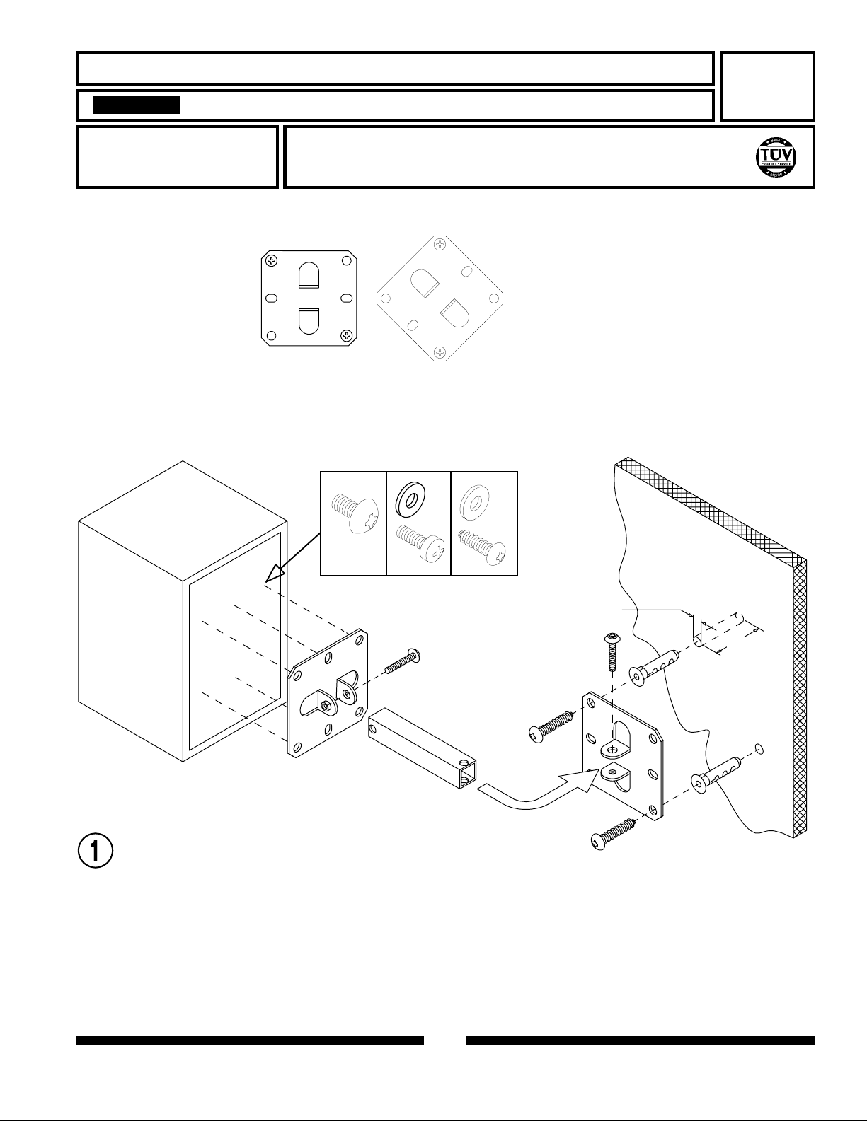
Note: Mounting plate (J)
may be attached at any
angle.
Peerless Industries, Inc.
1980 Hawthorne Avenue
Melrose Park, IL 60160
J
D
A
B
For customer service, call
1-800-729-0307 or
708-865-8870.
D
C
H
J
L
Attach one mounting plate (J) to back of speaker. Many
speakers have threaded inserts that will accept screws (A or
B). For speakers with wood or particle board backs that do
not contain threaded inserts drill four 1/8" (3mm) dia. holes
no deeper than 5/8" (16mm) and attach with #10 partical board
screws (C). Use washers (D) with screws (B or C).
Attach remaining mounting plate (J) to wall (or ceiling) and
assemble speaker mount as shown. Note: Plastic anchors (G)
may be used in concrete, concrete block, brick, wood, plaster,
or drywall.
F
1 1/32"
(9mm)
H
F
1 5/8"
(40mm)
G
J
G
1 of 2
087-9009 rev:A
K
A
H
or
E
D
B
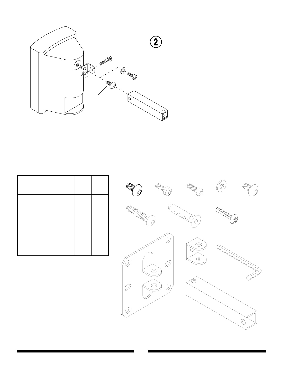
For speakers with a single
threaded insert use U-bracket (K)
instead of mounting plate (J).
Attach with 1/4-20 x 1/2" phillips
screw (A) or M6 x 1.0 x 10mm
phillips screw (E) or 10-32 x 1/2"
phillips screw and washer (B & D).
L
Parts List
Qty.
Description
A
4
1/4-20X1/2" phillips screw
8
10-32 x 1/2" phillips screw
B
8
#10 particle board screw
C
D
8
#10 flat washer
2
M6 x 1.0 x 10mm phillips screw
E
4
#14 x 1 1/4" phillips screw
F
G
4
plastic anchor
4
1/4-20 x 7/8" socket screw
H
4
mounting plate
J
K
2
U-bracket
2
wall arm
L
1
5/32" allen wrench
M
SPK810
Part No.
510-9108
520-9509
500-9006
540-9400
520-9401
510-9157
590-1025
520-9507
087-1001
087-1022
087-1021
560-9706
SPK810W
Part No.
520-9511
520-9510
510-9156
540-9442
520-9524
510-9158
590-1025
520-9508
087-2001
087-2022
087-2021
560-9706
A
B
F
G
C
H
D
E
K
M
J
L
087IN09A ISSUED: 5/20/96 REVISION: A 5/23/96 SHEET NO: 087-9009
© 2001 Peerless Industries, Inc. All rights reserved.
Peerless is a trademark of Peerless Industries, Inc.
2 of 2
 Loading...