

Page 1
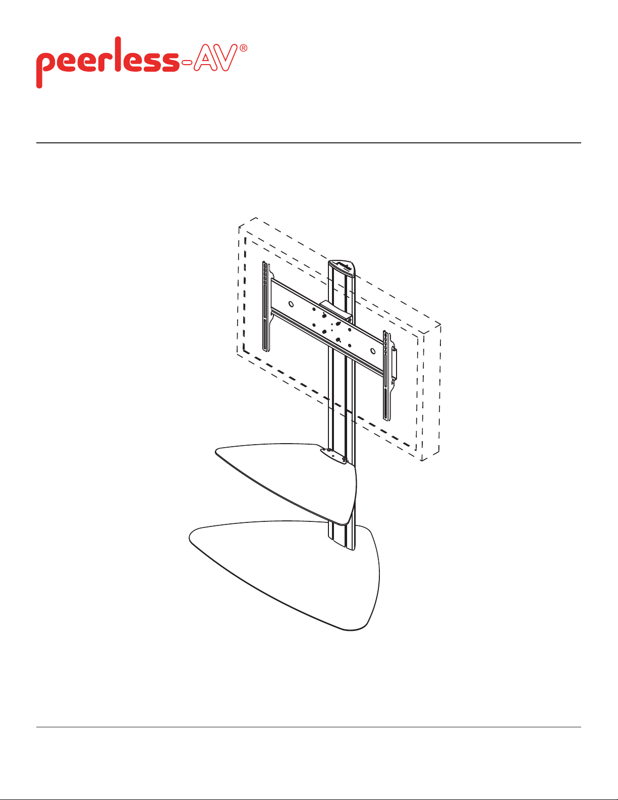
Installation and Assembly:
32" - 65" Flat Panel Display Stand
Model: SGLS01, SGLB01
Max Load Capacity:
150 lb (68 kg) display
50 lb (23 kg) per shelf
2300 White Oak Circle • Aurora, IL 60502 • (708) 865-2112 • Fax: (800) 359-6500 • www.peerless-av.com
ISSUED: 07-28-06 SHEET #: 202-9156-14 (2013-10-01)
Page 2
NOTE: Read entire instruction sheet before you start installation and assembly.
WARNING
• Do not begin to install your Peerless product until you have read and understood the instructions and warnings
contained in this Installation Sheet. If you have any questions regarding any of the instructions or warnings, please
call Peerless customer care at 1-708-865-2112.
• This product should only be installed by someone of good mechanical aptitude, and fully understands
these instructions.
• Never exceed the Maximum Load Capacity on page 1.
• Always use an assistant or mechanical lifting equipment to safely lift and position equipment.
• Tighten screws fi rmly, but do not overtighten. Overtightening can damage the items, greatly reducing their holding
power.
• The cart is not affi xed or secured to the fl oor, and may therefore tip over and/or fall if display and/or stand is shaken
or hit. Always monitor children and do not let children play alone around stand as they could get hurt by a falling
display. Not recommended for use in areas with heavy traffi c.
Tools Needed for Assembly
• level
• phillips screwdriver
Table of Contents
Parts List............................................................................................................................................................................ 3, 4
Assembling Floor Stand .........................................................................................................................................................4
Attaching Display Using Universal Plate with Adapter Brackets.............................................................................................7
Attaching Display with VESA 100 Mounting Pattern.............................................................................................................11
2 of 35
ISSUED: 07-28-06 SHEET #: 202-9156-14 (2013-10-01)
Page 3

A
SGLB01
SGLS01
Description Qty.
Part #
Part #
A screen mount bracket 1
201-1156
201-4156
B hook plate 1
201-1157
201-4157
C shelf support 1
201-1158
201-4158
D shelf clamp bracket 1
201-1159
201-4159
E base 1
201-1981
201-4981
F universal plate 1
201-1109
201-4109
G adapter bracket 2 201-1513
201-4513
H upright 1
580-1180
580-4180
I glass shelf 1
590-0208
590-0208
J top cover 1
590-1210
590-4210
K button bumper 9
590-1209
590-1209
L 1/4-20 x 12 mm decorative screw 12
520-2325
520-1325
M 1/4-20 x 20 mm decorative screw 2
520-2326
520-1326
N 1/4-20 nut 10
530-1050
530-2031
P 3/8-16 x 2.5" socket screw 3
520-9550
520-9550
Q 7/32" allen wrench 1
560-9715
560-9715
R 4 mm allen wrench 1
560-9646
560-9646
S adhesive felt 1
570-0043
570-0043
T M10 x 15 mm socket screw 4 520-9262
520-9262
U 6 mm allen wrench 1
560-9716
560-9716
Parts List
Before you begin, make sure all parts shown are included with your product.
B
C
NOTE: Some parts may appear slightly different than illustrated.
E
L
I
D
J
K
G
NM
H
S
UTP
F
Q
3 of 35
R
ISSUED: 07-28-06 SHEET #: 202-9156-14 (2013-10-01)
Page 4
Adapter Bracket Fasteners
M5 x 12 mm (4)
(520-1027)
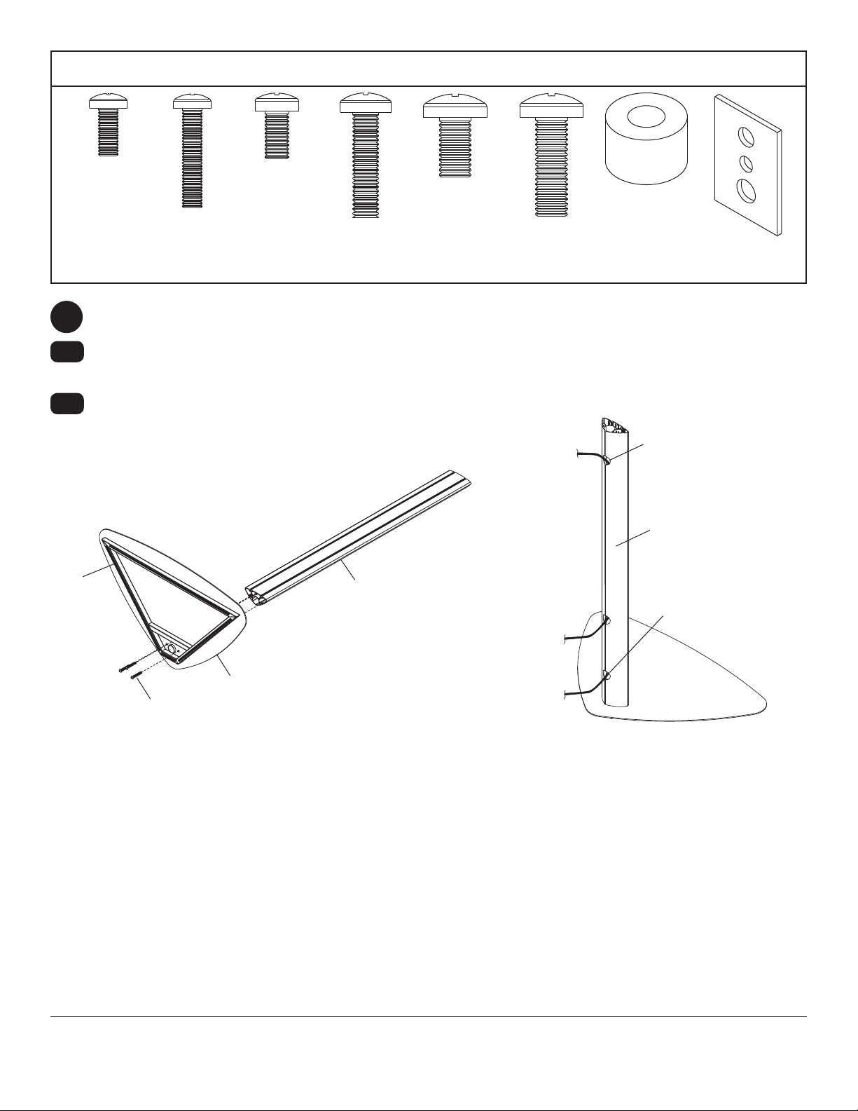
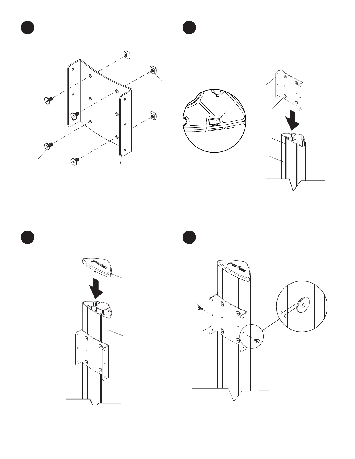
Cut adhesive felt (S) into four pieces as shown in fi gure 1.1 below and affi x to bottom of base (E).
1
1-1
1-2
Attach upright (H) to base (E) using three 3/8-16 x 2.5" socket screws (P). Tighten screws using 7/32" allen
wrench (Q).
Run cords through upright (H) using cord management holes as shown in fi gure 1.2.
M6 x 12 mm (4)
M5 x 25 mm (4)
(520-9543)
(520-1128)
M6 x 25 mm (4)
(520-1208)
M8 x 12 mm (4)
(520-9571)
M8 x 25 mm (4)
(520-1031)
.75" spacer (4)
(540-1059)
Multi-washer (4)
(580-1398)
CORD
MANAGEMENT HOLE
H
S
fi g. 1.1
P
E
H
CORD
MANAGEMENT HOLE
fi g. 1.2
4 of 35
ISSUED: 07-28-06 SHEET #: 202-9156-14 (2013-10-01)
Page 5
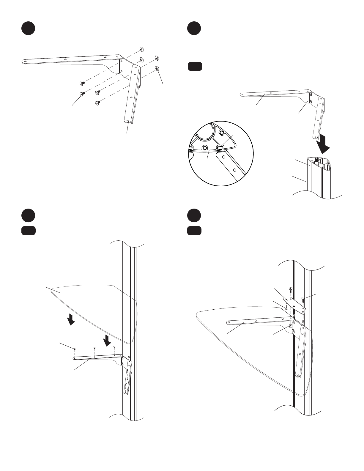
Loosely attach four 1/4-20 x 12 mm screws
2
(L) and 1/4-20 nuts (N) to shelf support (C).
N
3
3-1
Slide shelf support (C) onto upright (H) so that
1/4-20 nuts (N) slide into slots of upright (H) as
shown in fi gure 3 and detail 1. Slide shelf support
to desired position, level, then tighten 1/4-20 x 12
mm screws (L) using 4 mm allen wrench (R).
NOTE: Max of two shelves can be used
Max height of top shelf is 34" from base.
Max height of second shelf is 28" from base.
L
C
Insert six button bumpers (K) into shelf support
4 5
(C).
4-1
Place glass shelf (I) on shelf support.
H
DETAIL 1
5-1
C
L
N
SLOT
H
fi g. 3
Insert three button bumpers (K) into bottom of
shelf clamp bracket (D).
Attach shelf clamp bracket (D) to shelf support (C)
using two 1/4-20 x 20 mm screws (M) and two
1/4-20 nuts (N).
I
D
M
K
C
N
K
C
5 of 35
ISSUED: 07-28-06 SHEET #: 202-9156-14 (2013-10-01)
Page 6
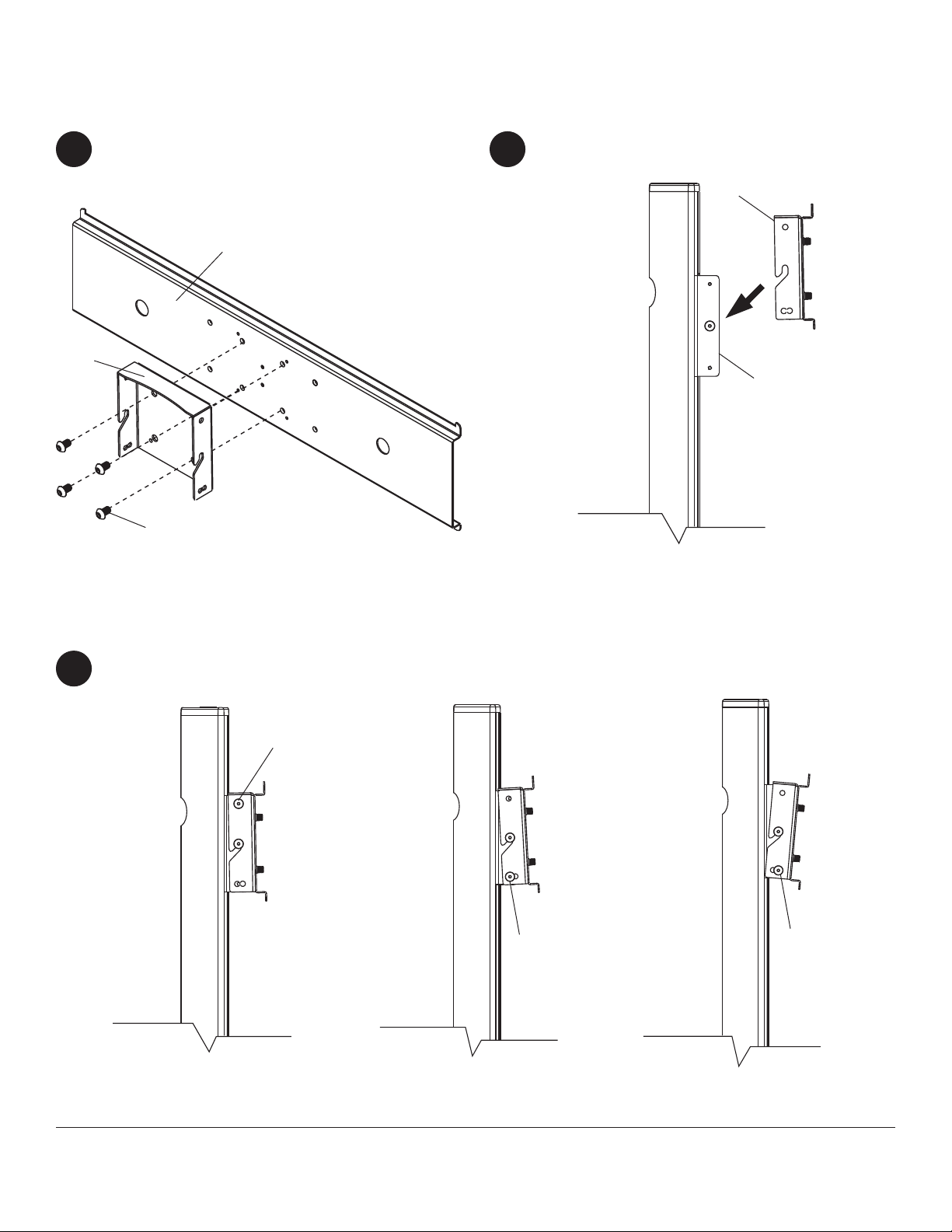
Loosely attach four 1/4-20 x 12 mm screws (L)
6
and 1/4-20 nuts (N) to display mount bracket (A).
Slide display mount bracket (A) onto upright (H)
7
so that 1/4-20 nuts (N) slide into slots of upright
(H) as shown in fi gure 7 and detail 2. Slide display
mount bracket to desired position, level, then
tighten 1/4-20 x 12 mm screws (L) using 4 mm
allen wrench (R).
L
Snap top cover (J) onto upright (H).
8
A
N
A
N
H
DETAIL 2
Insert two 1/4-20 x 12 mm screws (L) into display
9
mount bracket (A), leaving 1/8" of exposed thread
as shown in fi gure 9 and detail 3.
L
SLOT
H
fi g. 7
J
H
6 of 35
L
A
1/8"
DETAIL 3
fi g. 9
ISSUED: 07-28-06 SHEET #: 202-9156-14 (2013-10-01)
Page 7
Attaching Display Using Universal Plate with Adapter Brackets
For attaching displays with VESA 100 hole pattern, skip to page 11.
10
B
Attach universal plate (F) to hook plate (B) using
four M10 x 15 mm socket screws (T). Tighten
screws using 6 mm allen wrench (U).
F
T
11
Attach hook plate (B) to display mount bracket (A).
B
A
Insert two 1/4-20 x 12 mm screws (L) into holes indicated below for desired display orientation. Tighten all screws
12
using 4 mm allen wrench (R).
L
L
2° Backward Tilt 5° Forward TiltNo Tilt
L
7 of 35
ISSUED: 07-28-06 SHEET #: 202-9156-14 (2013-10-01)
Page 8
Installing Adapter Brackets
WARNING
• Tighten screws so adapter brackets are fi rmly attached. Do not tighten with excessive force. Overtightening can
cause stress damage to screws, greatly reducing their holding power and possibly causing screw heads to become
detached. Tighten to 40 in. • lb (4.5 N.M.) maximum torque.
• If screws don't get three complete turns in the display inserts or if screws bottom out and bracket is still not tightly
secured, damage may occur to display or product may fail.
13
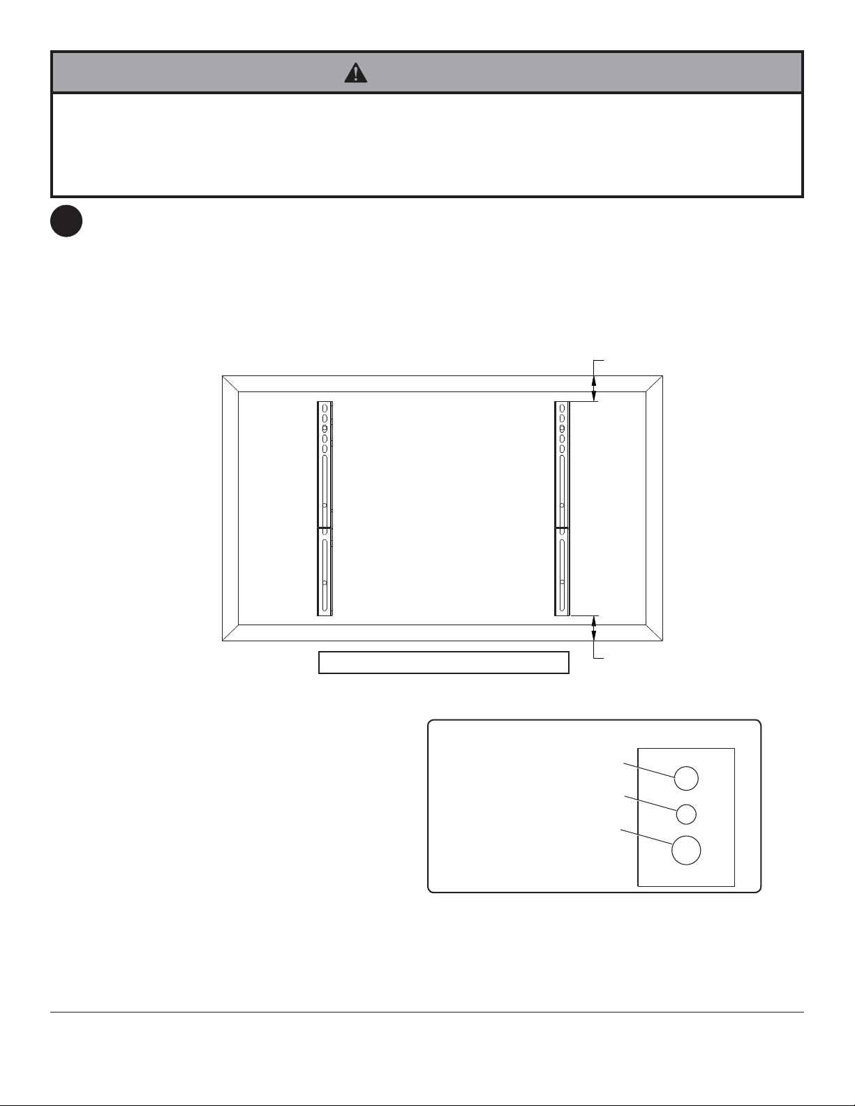
To prevent scratching the display, set a cloth on a fl at, level surface that will support the weight of the display.
Place display face side down. If display has knobs on the back, remove them to allow the adapter brackets to be
attached. Place adapter brackets (G) on back of display, align to holes, and center on back of display as shown
below. Attach the adapter brackets to the back of the display using the appropriate combination of screws, multiwashers and spacers as shown in fi gure 13.1 and 13.2.
NOTE: Top and bottom holes of display must always be used.
Verify that all holes are properly aligned, and then tighten screws using a phillips screwdriver.
X
G
CENTER BRACKETS VERTICALLY
ON BACK OF DISPLAY
Note: "X" dimensions should be equal.
Notes:
• The number of fasteners used will vary,
depending upon the type of display.
• Multi-washers and spacers may not be
used, depending upon the type of display.
• Use the corresponding hole in the multi-
washer that matches your screw size as
shown.
NOTE: For fl at back displays proceed to step 13-1. For bump-out or recessed back display skip to step 13-2.
MEDIUM HOLE FOR M5 SCREWS
SMALL HOLE FOR M4 SCREWS
LARGE HOLE FOR M6 SCREWS
8 of 35
ISSUED: 07-28-06 SHEET #: 202-9156-14 (2013-10-01)
X
MULTI-WASHER
Page 9
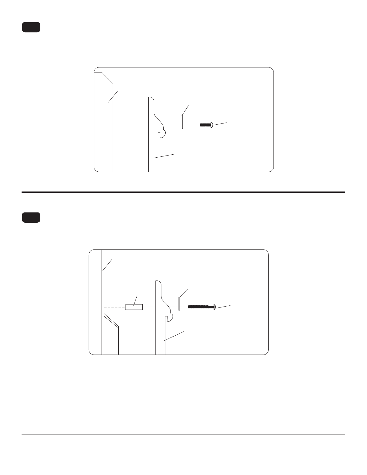
For Flat Back Display
13-1
Begin with the shortest length screw, hand thread through multi-washer and adapter bracket into display as
shown below. Screw must make at least three full turns into the mounting hole and fi t snug into place. Do not
over tighten. If screw cannot make three full turns into the display, select a longer length screw from the baffl ed
fastener pack. Repeat for remaining mounting holes, level brackets and tighten screws.
NOTE: Spacers may not be used, depending upon the type of display.
If you have any questions, please call Peerless customer care at 1-800-865-2112.
fi g. 13.1
DISPLAY
MULTI-WASHER
SCREW
ADAPTER
BRACKET (G)
For Bump-out or Recessed Back Display
13-2
Begin with longer length screw, hand thread through multi-washer, adapter bracket and spacer in that order into
display as shown below. Screw must make at least three full turns into the mounting hole and fi t snug into place.
Do not over tighten. If screw cannot make three full turns into the display, select a longer length screw from the
baffl ed fastener pack. Repeat for remaining mounting holes, level brackets and tighten screws.
DISPLAY
SPACER
If you have any questions, please call Peerless customer care at 1-800-865-2112.
fi g. 13.2
MULTI-WASHER
SCREW
ADAPTER
BRACKET (G)
9 of 35
ISSUED: 07-28-06 SHEET #: 202-9156-14 (2013-10-01)
Page 10
Mounting and Removing Flat Panel Display
WARNING
• Always use an assistant or mechanical lifting equipment to safely lift and position the display.
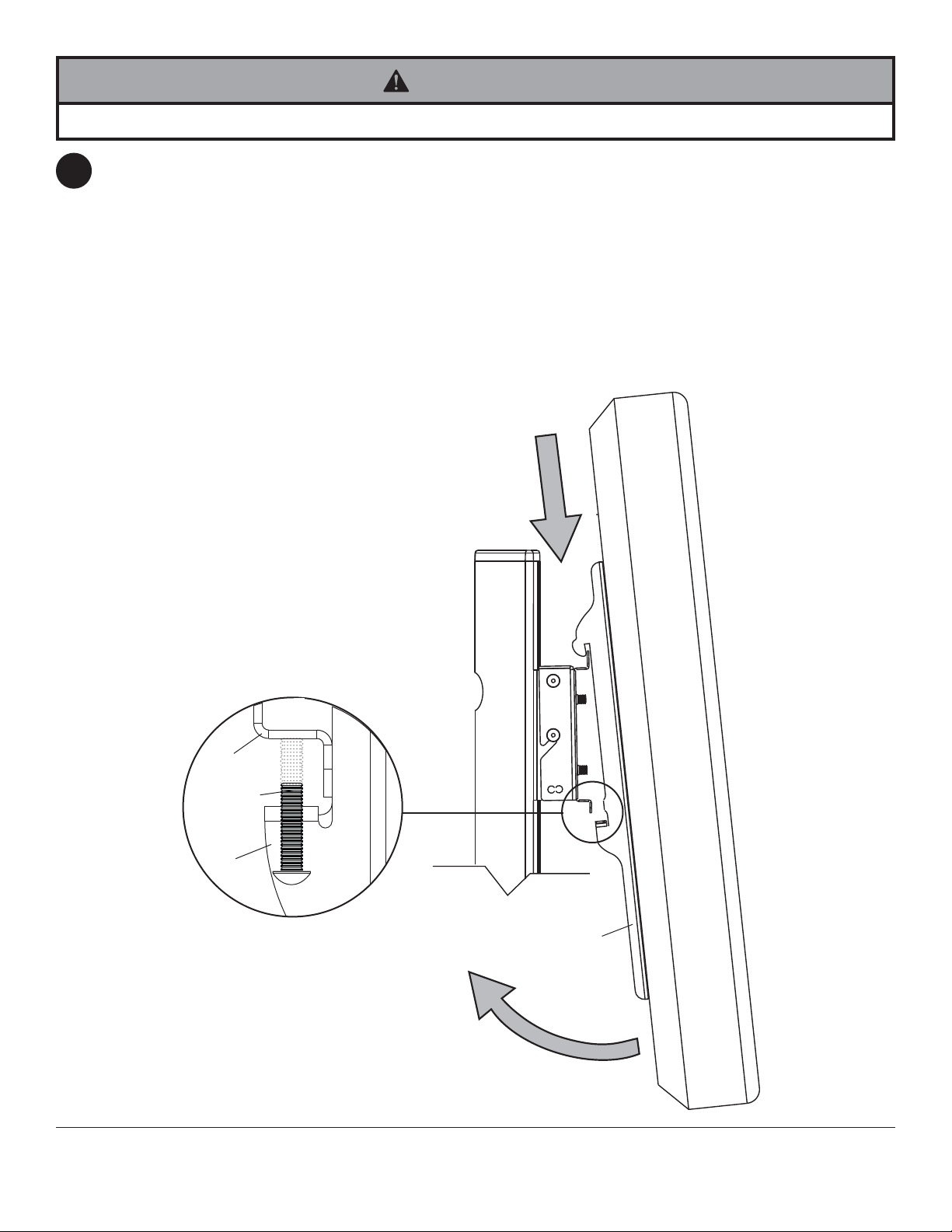
Hook adapter brackets (G) onto universal plate (F), then slowly swing display in as shown. Turn screws clockwise
14
at least six times to prevent display from being removed as shown in detail 4.
NOTE: Tighten using 4 mm allen wrench (R).
Display can be adjusted horizontally if desired.
NOTE: It is important to lock display down! To lock the display down, tighten screws to adapter bracket as
shown in detail 4.
To remove display from mount, loosen screws, swing display away from mount, and lift display off of mount.
F
SCREWS
G
DETAIL 4
10 of 35
G
ISSUED: 07-28-06 SHEET #: 202-9156-14 (2013-10-01)
Page 11
Attaching Display with VESA 100 Mounting Pattern
WARNING
• If screws don't get three complete turns in the display inserts or if screws bottom out and hook plate is still not tightly
secured, damage may occur to display or product may fail.
10
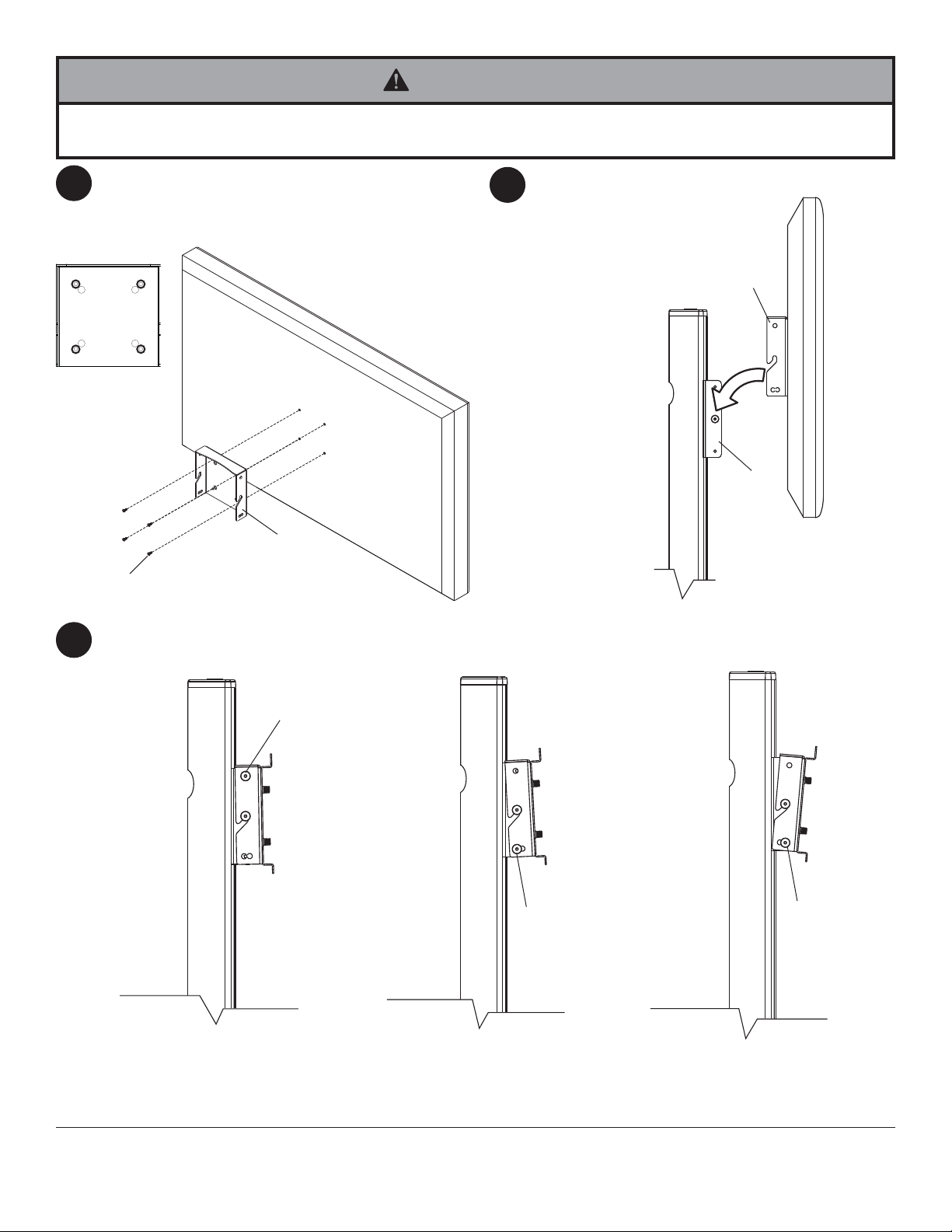
Choose hole pattern as shown in fi gure 10. Attach
hook plate (B) to back of display using four M4 x
12 mm screws. Tighten screws using a phillips
screwdriver.
fi g 10
M4 X 12 MM SCREWS
B
11
Attach hook plate (B) to display mount bracket (A).
B
A
Insert two 1/4-20 x 12 mm screws (L) into holes indicated below for desired display orientation. Tighten all screws
12
using 4 mm allen wrench (R).
L
L
No Tilt
2° Backward Tilt
5° Forward Tilt
L
11 of 35
All other brand and product names are trademarks or registered trademarks of their respective owners.
ISSUED: 07-28-06 SHEET #: 202-9156-14 (2013-10-01)
© 2013, Peerless Industries, Inc. All rights reserved.
Page 12

Installation et assemblage:
Support téléviseur sur piedpour écran plat 32"- 65"
Modèle: SGLS01, SGLB01
Capacité de charge maximale:
68 kg (150 lb) pour l’écran
22,7 kg (50 lb) par étagère
2300 White Oak Circle • Aurora, IL 60502 • (708) 865-2112 • Fax: (800) 359-6500 • www.peerless-av.com
ISSUED: 07-28-06 SHEET #: 202-9156-14 (2013-10-01)
Page 13

Français
Remarque : lisez entièrement la fi che d’instructions avant de commencer l’installation et l’assemblage.
AVERTISSEMENT
• Ne commencez pas à installer votre produit Peerless avant d’avoir lu et assimilé les instruncez pas à installer
votrections et les mises en garde contenues dans cette fi che d’installation. Pour toute questet les mises en garde
conion concernant les instructions ou les mises en garde, appelez le service à la clientèle de Peerless au
1-708-865-2112.
• Ce produit ne doit être installé que par une personne ayant de bonnes aptitudes en mécanique, expérimentée en
travaux de construction élémentaires, et démontrant une parfaite compréhension de ces instructions.
• Assurez-vous que la surface de support pourra soutenir sans danger la charge combinée de l’équipement, de toute
sa visserie et de tous ses composants.
• Ne dépassez jamais la capacité de charge maximale.
• Pour lever et positionner l’équipement en toute sécurité, faites-vous toujours aider par une autre personne ou
utilisez un matériel de levage mécanique.
• Serrez fermement les vis, mais sans excès. Un serrage excessif peut endommager les éléments et en réduire
considérablement le pouvoir de maintien.
• Le support n’est pas appliqué ni fi xé au plancher. Par conséquent il peut, de même que l’écran, basculer ou tomber
s’il est secoué ou heurté. Surveillez toujours les enfants et ne les laissez pas jouer seuls à proximité de ce support
car ils pourraient être blessés en cas de chute de l’écran. Déconseillé dans les endroits encombrés.
Outils nécessaires pour l’assemblage
• niveau
• tournevis cruciforme
Table des matières
Liste des pièces ............................................................................................................................................................14, 15
Assemblage du support téléviseur sur pied........................................................................................................................15
Fixation de l’écran à l’aide d’une plaque universelle et de supports adaptateurs ..............................................................18
Fixation de l’écran selon la confi guration de montage VESA 100 ...................................................................................... 22
13 sur 35
ISSUED: 07-28-06 SHEET #: 202-9156-14 (2013-10-01)
Page 14

Français
SGLB01
SGLS01
Description Qté Pièce nº Pièce nº
A support de montage d’écran 1
201-1156
201-4156
B plaque à crochets 1
201-1157
201-4157
C support d’étagère 1
201-1158
201-4158
D étrier de fixation d’étagère 1
201-1159
201-4159
E base 1
201-1981
201-4981
F plaque universelle 1
201-1109
201-4109
G support adaptateur 2 201-1513
201-4513
H montant 1
580-1180
580-4180
I étagère en verre 1
590-0208
590-0208
J protection supérieure 1
590-1210
590-4210
K tampon 9
590-1209
590-1209
L vis décorative 12
520-2325
520-1325
M vis décorative 2
520-2326
520-1326
N écrou 1/4-20 10
530-1050
530-2031
P vis à tête creuse 3/8-16 x 2,5 po 3
520-9550
520-9550
Q Clé hexagonale 0,556 cm (7/32 po) 1
560-9715
560-9715
R clé hexagonale 4 mm 1
560-9646
560-9646
S feutre adhésif 1
570-0043
570-0043
T vis à tête creuse M10 x 15 mm 4 520-9262
520-9262
U clé hexagonale 6 mm 1
560-9716
560-9716
Avant de commencer, assurez-vous que toutes les pièces indiquées sont incluses
avec le produit.
Liste des pièces
Il est possible que certaines pièces apparaissent légèrement différentes
de l’illustration.
A
D
J
B
C
G
K
E
L
I
F
Q
14 sur 35
NM
H
S
UTP
R
ISSUED: 07-28-06 SHEET #: 202-9156-14 (2013-10-01)
Page 15

Français
Éléments de fi xation cruciformes pour supports adaptateurs
M5 x 12 mm (4)
(520-1027)
M5 x 25 mm (4)
(520-9543)
Découpez le feutre adhésif (S) en quatre morceaux, comme illustré sur la fi gure 1.1 ci-dessous, et appliquez-les
1
sur le dessous de la base (E).
Fixez le montant (H) sur la base (E) à l’aide des trois vis à tête creuse 3/8-16 x 2,5 po (P). Serrez les
1-1
vis à l’aide de la clé hexagonale de 0,556 cm (7/32 po) (Q).
Faites passer les cordons au travers du montant (H) en utilisant les trous du système de gestion de
1-2
cordon, comme illustré sur la fi gure 1.2.
M6 x 12 mm (4)
(520-1128)
M6 x 25 mm (4)
(520-1208)
M8 x 12 mm (4)
(520-9571)
M8 x 25 mm (4)
(520-1031)
.75" spacer (4)
(540-1059)
Multi-washer (4)
trou du système de
gestion de cordon
H
(580-1398)
S
fi g. 1.1
P
E
H
trou du système de
gestion de cordon
fi g. 1.2
15 sur 35
ISSUED: 07-28-06 SHEET #: 202-9156-14 (2013-10-01)
Page 16

Sans les serrer, fi xez les quatre vis 1/4-20
2
x 12 mm (L) et les écrous 1/4-20 (N) sur le
support d’étagère (C).
L
N
Faites glisser le support d’étagère (C) sur le montant
3
(H) de manière à ce que les écrous 1/4-20 (N) glissent
dans les fentes du montant (H), comme illustré sur la
fi gure 3 et le plan détaille 1. Faites glisser le support
d’étagère jusqu’à la position désirée, mettez-le de
niveau, puis serrez les vis 1/4-20 x 12 mm (L) à l’aide
de la clé hexagonale de 4 mm (R).
REMARQUE : Il est possible d’utiliser un maximum de
3-1
deux étagères.
La hauteur maximale de l’étagère supérieure est 85 cm
(34 po) depuis la base.
La hauteur maximale de la deuxième étagère est 70
cm (28 po) depuis la base.
Français
Insérez les six tampons (K) dans le support
4
d’étagère (C).
Placez l’étagère en verre (I) sur son support.
4-1
I
C
N
C
L
H
FENTE
H
PLAN DÉTAILLÉ 1
Insérez les trois tampons (K) dans le bas de l’étrier de
5
fi xation d’étagère (D).
Fixez l’étrier de fi xation d’étagère (D) au support (C)
5-1
à l’aide des deux vis 1/4-20 x 20 mm (M) et des deux
écrous 1/4-20 (N).
fi g. 3
D
K
M
K
C
16 sur 35
C
ISSUED: 07-28-06 SHEET #: 202-9156-14 (2013-10-01)
N
Page 17

Sans les serrer, fi xez les quatre vis 1/4-20 x 12 mm
6
(L) et les écrous 1/4-20 (N) sur le support de montage
d’écran (A).
N
Faites glisser le support de montage d’écran (A) sur
7
le montant (H) de manière à ce que les écrous
1/4-20 (N) glissent dans les fentes du montant (H),
comme illustré sur la fi gure 7 et le plan détaille
2. Faites glisser le support de montage d’écran
jusqu’à la position désirée, mettez-le de niveau, puis
serrez les vis 1/4-20 x 12 mm (L) à l’aide de la clé
hexagonale de 4 mm (R).
A
N
L
H
FENTE
Français
L
PLAN DÉTAILLÉ 2
A
Encliquetez la protection supérieure (J) sur le
8 9
montant (H)
J
H
fi g. 7
Insérez les deux vis 1/4-20 x 12 mm (L) dans le
support de montage d’écran (A), en laissant 0,125
cm (1/8 po) de fi letage exposé, comme illustré sur la
fi gure 9 et le plan détaillé 3.
L
1/8"
H
17 sur 35
A
PLAN DÉTAILLÉ 3
fi g. 9
ISSUED: 07-28-06 SHEET #: 202-9156-14 (2013-10-01)
Page 18

Français
Fixation de l’écran à l’aide d’une plaque universelle et de supports
adaptateurs
Les instructions relatives à la fi xation des écrans selon la confi guration de montage VESA 100
se trouvent à la page 22
Fixez la plaque universelle (F) sur la plaque à
10
crochets (B) à l’aide des quatre vis à tête creuse
M10 x 15 mm (T). Serrez les vis à l’aide de la clé
hexagonale de 6 mm (U).
Fixez la plaque à crochets (B) sur le support de
11
montage d’écran (A).
B
F
B
A
T
Insérez les deux vis 1/4-20 x 12 mm (L) dans les trous indiqués ci-dessous pour l’orientation désirée de l’écran.
12
Serrez toutes les vis à l’aide de la clé hexagonale de 4 mm (R).
L
L
L
Aucune inclinaison
Inclinaison de 2°
vers l’arrière
18 sur 35
Inclinaison de 5°
vers l’avant
ISSUED: 07-28-06 SHEET #: 202-9156-14 (2013-10-01)
Page 19

Français
Installation des supports adaptateurs
AVERTISSEMENT
• Serrez les vis de manière à fi xer solidement les supports adaptateurs. N’employez pas une force excessive pour ce
faire. Un serrage excessif peut causer des contraintes risquant d’endommager les vis, de réduire considérablement
leur pouvoir de maintien et de décoller les têtes des vis. Serrez les vis à un couple maximum de 4,5 Nm (40 po-lb).
• Si les vis ne sont pas enfoncées de trois tours complets dans les inserts ou si elles sont serrées au maximum sans
parvenir à maintenir solidement le support, l’écran peut être abîmé ou le produit détérioré.
Pour éviter de rayer l’écran, placez un chiffon sur une surface plate et horizontale capable de supporter le poids de
13
l’écran. Placez l’écran sens dessus dessous. Si l’écran est muni de boutons à l’arrière, enlevez-les pour pouvoir fi x-
er les supports adaptateurs. Placez les supports adaptateurs (G) à l’arrière de l’écran, alignez-les sur les trous et
centrez-les sur l’arrière de l’écran, comme illustré ci-dessous. Fixez les supports adaptateurs à l’arrière de l’écran à
l’aide des vis, rondelles universelles et entretoises appropriées, comme illustré sur la fi gure 13.1 ou la fi gure 13.2.
Remarque: Les trous supérieurs et inférieurs doivent toujours être utilisés.
Vérifi ez que tous les trous sont correctement alignés, puis serrez les vis à l’aide d’un tournevis cruciforme.
X
VERTICALEMENT À
G
Remarque: Les dimensions « X » doivent être égales.
Remarques :
• Le nombre de fi xations utilisées varie
suivant le type d’écran.
• Il est possible que les rondelles universelles
et les pièces d’écartement ne soient pas
utilisées, suivant le type d’écran.
• Utilisez le trou de la rondelle universelle
correspondant à la dimension de la vis,
comme illustré.
L’ARRIÈRE DE L’ÉCRAN
CENTREZ LES
SUPPORTS
X
RONDELLE UNIVERSELLE
TROU MOYEN POUR VIS M5
PETIT TROU POUR VIS M4
GROS TROU POUR VIS M6
REMARQUE : Pour les écrans à dos plat, exécutez l’étape 13-1. Pour les écrans à dos convexes ou concaves passez
à l’étape 13-2.
19 sur 35
ISSUED: 07-28-06 SHEET #: 202-9156-14 (2013-10-01)
Page 20

Pour les écrans à dos plat
13-1
Commencez par la vis la plus courte et vissez-la manuellement à l’écran en la faisant passer à travers la rondelle
tout usage et le support adaptateur, comme indiqué ci-dessous. La vis doit effectuer au moins trois tours complets
dans le trou de fi xation et tenir solidement en place. Ne pas trop serrer. S’il est impossible d’effectuer trois tours
de vis complets, choisissez une vis plus longue dans le jeu de fi xations à compartiments. Répétez pour le reste
des trous de fi xations, mettez les supports à niveau et resserrez les vis.
REMARQUE : Il n’est pas toujours nécessaire d’utiliser des entretoises, selon le type d’écran.
Français
fi g. 13.1
ÉCRAN
RONDELLE
TOUT USAGE
VIS
SUPPORT
ADAPT ATEUR (G)
Pour toute question, veuillez appeler le service à la clientèle de Peerless au 1-800-729-0307.
Pour un écran à dos convexe ou concave
13-2
Commencez par la vis la plus longue et vissez-la manuellement à l’écran en la faisant passer à travers la rondelle
tout usage, le support adaptateur et l’entretoise comme indiqué ci-dessous. La vis doit effectuer au moins
trois tours complets dans le trou de fi xation et tenir solidement en place. Ne pas trop serrer. S’il est impossible
d’effectuer trois tours de vis complets, choisissez une vis plus longue dans le jeu de fi xations à compartiments.
Répétez pour le reste des trous de fi xations, mettez les supports à niveau et resserrez les vis.
ÉCRAN
ENTRETOISE
fi g. 13.2
RONDELLE
TOUT USAGE
VIS
SUPPORT
ADAPT ATEUR (G)
Pour toute question, veuillez appeler le service à la clientèle de Peerless au 1-800-729-0307.
20 sur 35
ISSUED: 07-28-06 SHEET #: 202-9156-14 (2013-10-01)
Page 21

Montage et démontage de l’écran plat
AVERTISSEMENT
• Pour lever et positionner l’écran plasma en toute sécurité, faites-vous toujours aider par une autre personne ou
utilisez un matériel de levage mécanique.
Français
14
Accrochez les supports adaptateurs (G) sur la plaque universelle (F), puis faites lentement pivoter l’écran pour le
mettre en place, comme illustré. Tournez les vis dans le sens horaire au moins six fois pour empêcher l’écran de
se détacher, comme illustré sur le plan détaillé 4.
Remarque: Serrez les vis à l’aide de la clé hexagonale de 4 mm (R).
L’écran peut être ajusté horizontalement au besoin.
Remarque: Il est important de verrouiller l’écran. Pour ce faire, serrez les vis sur le support adaptateur,
comme illustré sur le plan détaillé 4.
Pour enlever l’écran de la monture, desserrez les vis, faites pivoter l’écran pour l’écarter de la monture et sou-
levez-le pour l’en retirer.
F
VIS
G
PLAN DÉTAILLÉ 4
21 sur 35
G
ISSUED: 07-28-06 SHEET #: 202-9156-14 (2013-10-01)
Page 22

Français
Fixation de l’écran selon la confi guration de montage VESA 100
AVERTISSEMENT
• Si les vis ne sont pas enfoncées de trois tours complets dans les inserts ou si elles sont serrées au maximum sans
parvenir à fi xer solidement la plaque, l’écran peut être abîmé ou le produit détérioré.
Choisissez la confi guration illustrée sur la fi gure 10.
10
Fixez la plaque à crochets (B) à l’arrière de l’écran
à l’aide des quatre vis M4 x 12 mm Serrez les vis à
l’aide d’un tournevis cruciforme.
fi g 10
VIZ M4 X 12 MM
Insérez les deux vis 1/4-20 x 12 mm (L) dans les trous indiqués ci-dessous pour l’orientation désirée de l’écran.
12
Serrez les vis à l’aide de la clé hexagonale de 4 mm (R).
B
Fixez la plaque à crochets (B) sur le support de
11
montage d’écran (A).
B
A
L
Aucune inclinaison
L
Inclinaison de 2°
vers l’arrière
22 sur 35
L
Inclinaison de 5°
vers l’avant
ISSUED: 07-28-06 SHEET #: 202-9156-14 (2013-10-01)
All other brand and product names are trademarks or registered trademarks of their respective owners.
© 2013, Peerless Industries, Inc. All rights reserved.
Page 23

Instalación y Ensamblaje:
Pedestal de Televisión de 32" - 65" Pantallas Planas
Modelo: SGLS01, SGLB01
Capacidad de carga máxima:
150 lib. (68 kilo) pantalla
50 lib. (22.7 kilo) por anaquel
2300 White Oak Circle • Aurora, IL 60502 • (708) 865-2112 • Fax: (800) 359-6500 • www.peerless-av.com
ISSUED: 07-28-06 SHEET #: 202-9156-14 (2013-10-01)
Page 24

Nota: Lea todas las instrucciones antes de comenzar la instalación y el ensamblaje.
Español
ADVERTENCIA
• No comience a instalar su producto Peerless hasta que haya leído y comprendido las instrucciones y advertencias
en la Hoja de instalación. Si tiene alguna pregunta respecto a cualquiera de las instrucciones o advertencias, llame
a atención del cliente Peerless al 1-708-865-2112.
• Este producto sólo debe ser instalado por una persona con buena aptitud mecánica que tenga experiencia básica
de construcción y que comprenda estas instrucciones a cabalidad.
• Asegúrese de que la superfi cie de apoyo sostendrá de forma segura la carga combinada del equipo y de todos los
componentes y la cerrajería que llevan.
• Nunca exceda la capacidad de carga máxima.
• Siempre procure un ayudante o use equipo mecánico para levantar y situar el equipo de modo seguro.
• Ajuste los tornillos con fi rmeza pero no los apriete demasiado. Al apretarlos demasiado, se pueden dañar y reducir
en gran medida su capacidad para agarrar
• El pedestal no está fi jado al piso y, por lo tanto, podría volcarse o caerse si se golpea o sacude la pantalla o el
pedestal. Supervise a los niños continuamente y no les permita jugar solos cerca del pedestal ya que podrían lastimarse si se cae la pantalla. No se recomienda su uso en áreas de mucho tráfi co.
Herramientas necesarias para el montaje
• nivel
• destornillador de cruz (phillips)
Contenido
Lista de las partes .........................................................................................................................................................25, 26
Ensamblaje del pedestal .....................................................................................................................................................26
Fijación de la pantalla con placa universal y soportes de adaptación .................................................................................29
Fijación de la pantalla con patrón de montaje para VESA 100 ...........................................................................................33
24 de 35
ISSUED: 07-28-06 SHEET #: 202-9156-14 (2013-10-01)
Page 25

Español
SGLB01
SGLS01
Descripción Cant. Nº de pieza Nº de pieza
A puntal para montar la pantalla 1
201-1156
201-4156
B placa de gancho 1
201-1157
201-4157
C soporte para anaquel 1
201-1158
201-4158
D puntal para abrazadera de anaquel 1
201-1159
201-4159
E base 1
201-1981
201-4981
F placa universal 1
201-1109
201-4109
G soporte de adaptación 2 201-1513
201-4513
H montante 1
580-1180
580-4180
I anaquel de cristal 1
590-0208
590-0208
J cubierta superior 1
590-1210
590-4210
K botón amortiguador 9
590-1209
590-1209
L tornillo decorativo de 1/4-20 x 12 mm 12
520-2325
520-1325
M tornillo decorativo de 1/4-20 x 20 mm 2
520-2326
520-1326
N tuerca 1/4-20 10
530-1050
530-2031
P tornillo de cabeza hueca 3/8-16 x 2.5" 3
520-9550
520-9550
Q llave allen de 7/32" 1
560-9715
560-9715
R llave allen de 4 mm 1
560-9646
560-9646
S fieltro adhesivo 1
570-0043
570-0043
T tornillo de cabeza hueca M10 x 15 mm 4 520-9262
520-9262
U llave allen de 6 mm 1
560-9716
560-9716
Antes de comenzar, asegúrese de que su producto incluye todas las piezas
ilustradas.
Lista de piezas
NOTA: Algunas partes pueden diferir un poco de las ilustradas.
A
D
J
B
C
G
K
E
L
I
F
Q
25 de 35
NM
H
S
UTP
R
ISSUED: 07-28-06 SHEET #: 202-9156-14 (2013-10-01)
Page 26

Fijadores para soportes de adaptación Phillips
Español
M5 x 12 mm (4)
(520-1027)
M5 x 25 mm (4)
(520-9543)
Corte el fi eltro adhesivo (S) en cuatro, como se muestra en la ilustración 1.1, y fíjelo a la parte inferior de la base (E).
1
Una el montante (H) a la base (E) con tres tornillos de cabeza hueca de 3/8-16 x 2.5" (P). Ajuste los
1-1
tornillos con una llave allen de 7/32" (Q).
Inserte los cables al montante (H) por los hoyos para manejo de cables, según se muestra en la
1-2
ilustración 1.2.
M6 x 12 mm (4)
(520-1128)
M6 x 25 mm (4)
(520-1208)
M8 x 12 mm (4)
(520-9571)
M8 x 25 mm (4)
(520-1031)
.75" spacer (4)
(540-1059)
Multi-washer (4)
(580-1398)
hoyo para manejo de
cables
H
S
fi g. 1.1
P
E
H
hoyo para manejo de
cables
fi g. 1.2
26 de 35
ISSUED: 07-28-06 SHEET #: 202-9156-14 (2013-10-01)
Page 27

Coloque, pero no ajuste, cuatro tornillos de 1/4-20
2
x 12 mm (L) y tuercas de 1/4-20 (N) al soporte para
el anaquel (C).
L
N
Deslice el soporte para el anaquel (C) al montante
3
(H) de modo que las tuercas de 1/4-20 (N) se
deslicen en las ranuras del montante (H) según
se muestra en la ilustración 3 y en el detalle 1.
Coloque el soporte en la posición deseada, nivélelo
y entonces ajuste los tornillos de 1/4-20 x 12 mm
(L) con una llave allen de 4 mm (R).
NOTA: Se puede usar un máximo de dos
3-1
anaqueles. La altura máxima del anaquel superior
es 34" desde la base. La altura máxima del
segundo anaquel es 28" desde la base.
Español
C
Inserte seis botones amortiguadores (K) en el
4
soporte para el anaquel (C).
Coloque el anaquel de cristal (I) sobre el soporte
4-1
para el anaquel.
I
N
C
L
H
RANURA
H
DETALLE 1
Inserte tres botones amortiguadores (K) en la parte
5
inferior del puntal para la abrazadera del anaquel
(D).
Una el puntal para la abrazadera del anaquel (D) al
5-1
soporte para el anaquel (C) con dos tornillos de
1/4-20 x 20 mm (M) y dos tuercas de 1/4-20 (N).
D
K
fi g. 3
M
K
C
27 de 35
C
ISSUED: 07-28-06 SHEET #: 202-9156-14 (2013-10-01)
N
Page 28

Coloque, pero no ajuste, cuatro tornillos de 1/4-20
6
x 12 mm (L) y tuercas de 1/4-20 (N) al puntal para
montar la pantalla (A).
N
Deslice el puntal para montar la pantalla (A) al
7
montante (H) de modo que las tuercas de 1/4-20
(N) se deslicen en las ranuras del montante (H)
según se muestra en la ilustración 7 y en el detalle
2. Coloque el puntal para montar la pantalla en la
posición deseada, nivélelo y entonces ajuste los
tornillos de 1/4-20 x 12 mm (L) con una llave allen
de 4 mm (R).
Español
L
A
Fije la cubierta superior (J) presionándola contra el
8
montante (H).
N
H
DETALLE 2
A
L
RANURA
H
Inserte dos tornillos de 1/4-20 x 12 mm (L) al puntal
9
para montar la pantalla (A), y deje un 1/8" de la
rosca expuesta, según se muestra en la ilustración
9 y en el detalle 3.
fi g. 7
J
H
28 de 35
L
1/8"
A
DETALLE 3
fi g. 9
ISSUED: 07-28-06 SHEET #: 202-9156-14 (2013-10-01)
Page 29

Fijación de la pantalla con placa universal y soportes de adaptación
Para fi jar pantallas con el patrón de hoyos VESA 100, pase a la página 33.
Español
Una la placa universal (F) al la placa de gancho (B)
10
con cuatro tornillos de cabeza hueca M10 x 15 mm (T).
Apriete los tornillos con una llave allen de 6 mm (U).
F
B
T
Una la placa de gancho (B) al puntal para montar la
11
pantalla (A).
B
A
Inserte dos tornillos 1/4-20 x 12 mm (L) en los hoyos que se indican abajo para orientar la pantalla en la forma
12
deseada. Apriete todos los tornillos con una llave allen de 4 mm (R).
L
L
Sin inclinación
Inclinada hacia
atrás 2°
Inclinada hacia
adelante 5°
L
29 de 35
ISSUED: 07-28-06 SHEET #: 202-9156-14 (2013-10-01)
Page 30

Español
Cómo instalar los soportes de adaptación
ADVERTENCIA
• Ajuste los tornillos para fi jar los soportes de adaptación con fi rmeza. No use fuerza excesiva. Apretarlos demasiado
puede causar daño a los tornillos, reducir en gran medida su capacidad para agarrar y podría desprenderles la
cabeza. Apriete a un máximo de 40 plg. • lib. (4.5 N.M.).
• Si no puede dar tres vueltas completas a los tornillos en las inserciones de la pantalla o si los tornillos no tocan
fondo y el soporte todavía no está fi jado con fi rmeza, la pantalla puede sufrir daños o el producto podría fallar.
Para evitar rayar la pantalla, coloque un paño sobre una superfi cie plana y nivelada que aguante el peso de la
13
pantalla. Coloque la pantalla boca abajo. Si tiene botones en la parte de atrás, remuévalos para poder conectar
los soportes. Coloque los soportes adaptadores (G) en la parte trasera de la pantalla, alinéelos con los agujeros
y centralícelos en la parte trasera de la pantalla, como se muestra abajo. Fije los soportes adaptadores en la parte
trasera de la pantalla utilizando la combinación adecuada de tornillos, arandelas múltiples y espaciadores, como se
muestra en la fi gura 13.1 o en la fi gura 13.2.
Nota: Siempre use tanto los hoyos superiores como los inferiores.
Verifi que que todos los hoyos estén debidamente alineados y apriete los tornillos con un destornillador de cruz
(phillips).
X
G
Nota: Las dimensiones “X” deben ser iguales.
Notas:
• El número de fi jadores que necesite
variará según el tipo de pantalla.
• Puede que no necesite multi-arandelas ni
espaciadores, según el tipo de pantalla.
• Use el hoyo de la multi-arandela que
corresponda al tamaño del tornillo que
usará, como se muestra en la ilustración.
CENTRALICE LOS SOPORTES
VERTICALMENTE EN
LA PARTE DE ATRÁS DE LA
PANTALLA
X
MULTI-ARANDELA
HOYO MEDIANO PARA
TORNILLOS M5
HOYO PEQUEÑO PARA
TORNILLOS M4
HOYO GRANDE PARA
TORNILLOS M6
NOTA: En el caso de los televisores que tienen la parte posterior plana, pase al paso 13-1. En el caso de los televisores
que tienen la parte posterior abultada o empotrada, pase al paso 13-2.
30 de 35
ISSUED: 07-28-06 SHEET #: 202-9156-14 (2013-10-01)
Page 31

Instalación de un televisor que tiene la parte posterior plana
13-1
Comience con uno de los tornillos más cortos, enrósquelo, con la mano, a través de la arandela múltiple y el
soporte adaptador a la parte posterior de la pantalla, como se muestra abajo. El tornillo debe dar, por lo menos,
tres vueltas completas dentro del agujero de instalación y debe quedar ajustado en su lugar. No apriete los
tornillos en exceso. Si el tornillo no puede dar tres vueltas completas al entrar en la parte posterior de la pantalla,
seleccione un tornillo más largo de los sujetadores identifi cados y clasifi cados en las divisiones del empaque
plástico. Siga el mismo procedimiento con los agujeros de instalación restantes, nivele los soportes y apriete los
tornillos.
NOTA: Es posible que no necesite usar los espaciadores, dependiendo del tipo de pantalla.
PANTALLA
ARANDELA
MÚLTIPLE
SOPORTE
ADAPTADOR (G)
Español
fi g. 13.1
TORNILLO
Si tiene alguna pregunta, por favor, llame a servicio al cliente de Peerless al 1-800-729-0307.
Instalación de un televisor que tiene la parte posterior abultada o empotrada
13-2
Comience con uno de los tornillos más largos, enrósquelo, con la mano, a través de la arandela múltiple, el
soporte adaptador y el espaciador, en ese orden, a la parte posterior de la pantalla, como se muestra abajo. El
tornillo debe dar, por lo menos, tres vueltas completas dentro del agujero de instalación y debe quedar ajustado
en su lugar. No apriete los tornillos en exceso. Si el tornillo no puede dar tres vueltas completas al entrar en la
parte posterior de la pantalla, seleccione un tornillo más largo de los sujetadores identifi cados y clasifi cados
en las divisiones del empaque plástico. Siga el mismo procedimiento con los agujeros de instalación restantes,
nivele los soportes y apriete los tornillos.
PANTALLA
ESPACIADOR
ARANDELA
MÚLTIPLE
fi g. 13.2
TORNILLO
SOPORTE
ADAPTADOR (G)
Si tiene alguna pregunta, por favor, llame a servicio al cliente de Peerless al 1-800-729-0307.
31 de 35
ISSUED: 07-28-06 SHEET #: 202-9156-14 (2013-10-01)
Page 32

Cómo montar y remover una pantalla de panel plano
Español
ADVERTENCIA
• Siempre procure un ayudante o use equipo mecánico para levantar y situar el televisor de plasma de modo seguro.
Enganche los soportes de adaptación (G) en la placa universal (F), luego gire la pantalla lentamente como se
14
muestra. Voltee los tornillos en la dirección de las manecillas del reloj por lo menos seis veces para evitar que se
remueva la pantalla, como se muestra en el detalle 4.
Nota: Apriete con una llave allen de 4 mm (R).
La pantalla puede ajustarse horizontalmente si lo desea.
Nota: Es importante trabar la pantalla! Para trabar la pantalla, apriete los tornillos del soporte de adaptación
según se muestra en el detalle 4.
Para remover la pantalla de la montura, afl oje los tornillos, gire la pantalla alejándola de la montura y levante la
pantalla de la montura.
F
TORNILLOS
G
DETALLE 4
32 de 35
G
ISSUED: 07-28-06 SHEET #: 202-9156-14 (2013-10-01)
Page 33

Español
Fijación de la pantalla con el Patrón de montaje VESA 100
ADVERTENCIA
• Si no puede dar tres vueltas completas a los tornillos en las inserciones de la pantalla o si los tornillos no tocan fondo
y la placa de gancho todavía no está fi jada con fi rmeza, la pantalla puede sufrir daños o el producto podría fallar.
Escoja el patron de hoyos según se muestra en la
10
ilustración 10. Fije la placa de gancho (B) a la parte
de atrás de la pantalla con cuatro tornillos M4 x 12
mm. Apriete los tornillos con un destornillador de
cruz (phillips).
Fije la placa de gancho (B) al puntal para montar la
11
pantalla (A).
B
fi g 10
A
B
TORNILLOS M4 X 12 MM
Inserte dos tornillos de 1/4-20 x 12 mm (L) en los hoyos que se indican abajo para lograr la orientación deseada de
12
la pantalla. Apriete todos los tornillos con una llave allen de 4 mm (R).
Sin inclinación
L
L
Inclinada hacia
atrás 2°
33 de 35
All other brand and product names are trademarks or registered trademarks of their respective owners.
L
Inclinada hacia
adelante 5°
ISSUED: 07-28-06 SHEET #: 202-9156-14 (2013-10-01)
© 2013, Peerless Industries, Inc. All rights reserved.
Page 34

LIMITED FIVE-YEAR WARRANTY
Peerless Industries, Inc. (“Peerless”) warrants to original end-users of Peerless® products will be free from defects in material and workmanship, under normal
use, for a period of fi ve years from the date of purchase by the original end-user (but in no case longer than six years after the date of the product’s manufacture).
In no event shall the duration of any implied warranty of merchantability or fi tness for a particular purpose be longer than the period of the applicable
express warranty set forth above. Some states do not allow limitations on how long an implied warranty lasts, so the above limitation may not apply to you.
This warranty does not cover damage caused by (a) service or repairs by the customer or a person who is not authorized for such service or repairs by Peerless,
(b) the failure to utilize proper packing when returning the product, (c) incorrect installation or the failure to follow Peerless’ instructions or warnings when installing,
In no event shall Peerless be liable for incidental or consequential damages or damages arising from the theft of any product, whether or not secured
by a security device which may be included with the Peerless® product. Some states do not allow the exclusion or limitation of incidental or consequential
This warranty is in lieu of all other warranties, expressed or implied, and is the sole remedy with respect to product defects. No dealer, distributor, installer or other
person is authorized to modify or extend this Limited Warranty or impose any obligation on Peerless in connection with the sale of any Peerless® product.
At its option, Peerless will repair or replace, or refund the purchase price of, any product which fails to conform with this warranty.
using or storing the product, or (d) misuse or accident, in transit or otherwise, including in cases of third party actions and force majeure.
damages, so the above limitation or exclusion may not apply to you.
This warranty gives specifi c legal rights, and you may also have other rights which vary from state to state.
www.peerless-av.com
© 2013 Peerless Industries, Inc.
Español
GARANTÍA LIMITADA DE CINCO AÑOS
Peerless Industries, Inc. (Peerless) les garantiza a los usuarios fi nales originales de los productos Peerless® que los productos Peerless® estarán libres de
defectos de materiales o de manufactura, en condiciones de uso normal, durante un periodo de cinco (5) años a partir de la fecha en la que el usuario fi nal
original compre cualquier producto (pero, en ningún caso, durante un periodo mayor de 6 años después de la fecha de manufactura del producto). Queda a la
La duración de toda garantía implícita de comerciabilidad o de idoneidad para un propósito en particular no sobrepasará en caso alguno el periodo
de vigencia de la garantía explícita correspondiente indica en lo anterior. Algunos Estados no permiten que se establezcan limitaciones en relación con el
Esta garantía no cubre daños causados por (a) trabajos de mantenimiento o de reparación hechos por el cliente o alguna persona que no esté autorizada por
Peerless para realizar dichos trabajos de mantenimiento o de reparación, (b) no empacar el producto como es debido si lo devuelve, (c) hacer una instalación
incorrecta o no seguir las instrucciones o las advertencias de Peerless al instalar, utilizar o guardar el producto o (d) el mal uso o los accidentes, en tránsito o en
Peerless no tendrá responsabilidad en ningún caso de daños y perjuicios incidentales o indirectos o de daños y perjuicios que surjan por el robo de
cualquier producto, ya sea que el mismo esté o no esté asegurado con un dispositivo de seguridad que se haya incluido con el producto de Peerless®.
Algunos Estados no permiten que se excluyan o se establezcan limitaciones en relación con los daños y perjuicios incidentales o indirectos, de manera que es
Esta garantía remplaza toda otra garantía, expresa o implícita, y es el único recurso en lo que respecta a los defectos del producto. Ningún concesionario,
distribuidor, instalador ni ninguna otra persona está autorizada a modifi car o extender esta Garantía Limitada ni a imponer obligación alguna a Peerless en
Esta garantía concede derechos específi cos creados por ley y es posible que usted, además, tenga otros derechos que varían de acuerdo con el Estado donde
discreción de Peerless, reparar, reemplazar o rembolsar el precio de compra de cualquier producto que no cumpla esta garantía.
periodo de duración de una garantía implícita, de manera que es posible que la limitación expuesta en lo anterior no sea pertinente a usted.
otras circunstancias, incluidos los casos relacionados con las acciones de terceros o una fuerza mayor.
posible que la limitación o la exclusión expuesta en lo anterior no sea pertinente a usted.
relación con la venta de cualquier producto de Peerless®.
se encuentre.
www.peerless-av.com
34 of 35
© 2013 Peerless Industries, Inc.
ISSUED: 07-28-06 SHEET #: 202-9156-14 (2013-10-01)
Page 35

Français
GARANTIE DE CINQ ANS
Peerless Industries, Inc. (« Peerless ») garantit aux utilisateurs fi naux d’origine des produits PeerlessMD que lesdits produits ne présenteront aucun défaut de
matériau ou de main-d’œuvre, dans la mesure où ils sont utilisés normalement, pendant une période de cinq ans à compter de la date d’achat par l’utilisateur fi nal
d’origine (mais en aucun cas plus de six ans après la date de fabrication du produit). Peerless, à sa discrétion, réparera ou remplacera tout produit non conforme
La durée de toute garantie implicite de qualité commerciale ou d’application à un usage particulier n’excédera en aucun cas la durée de la garantie
applicable expressément stipulée plus haut. Certains états ou provinces n’autorisent pas la limitation de la durée d’une garantie implicite, et la limitation ci-
Cette garantie ne couvre pas les dommages causés par (a) un entretien ou des réparations effectués par l’acheteur ou une personne non autorisée par Peerless
à effectuer un tel entretien ou de telles réparations, (b) un emballage inadéquat lors de l’expédition d’un produit retourné, (c) une installation incorrecte ou le non-
respect des instructions ou mises en garde de Peerless lors de l’installation, l’utilisation ou le rangement du produit, ou (d) une mauvaise utilisation ou un accident
survenu lors d’un transport ou autrement, y compris l’intervention de tiers et les cas de force majeure.
Peerless ne peut en aucun cas être tenu responsable de quelque dommage accessoire ou indirect que ce soit ni de dommages résultant du vol
d’un quelconque produit, que celui-ci ait été ou non protégé par un dispositif de sécurité intégré à un produit Peerless
n’autorisent pas l’exclusion ou la restriction des dommages accessoires ou indirects, et il est possible que les restrictions ou exclusions ci-dessus ne s’appliquent
Les dispositions de cette garantie remplacent toute autre garantie expresse ou implicite et constituent le seul recours possible en cas de défectuosité d’un
produit. Aucun marchand, distributeur, installateur ou autre personne n’est autorisé à modifi er ou étendre la portée de cette garantie limitée, ni à imposer quelque
obligation ce que soit à Peerless en ce qui concerne la vente de tout produit Peerless
Cette garantie offre des droits juridiques particuliers auxquels peuvent s’ajouter d’autres droits, susceptibles de varier d’une province ou d’un état à l’autre.
aux termes de cette garantie, ou en remboursera le prix d’achat.
dessus peut donc ne pas vous être applicable.
pas à votre cas.
MD
. Certains états ou provinces
MD
.
Patented. Design Patent No. D539,566. Utiltiy Patent No. 8,517,322.
www.peerless-av.com
© 2013 Peerless Industries, Inc.
35 of 35
ISSUED: 07-28-06 SHEET #: 202-9156-14 (2013-10-01)
 Loading...