

Page 1
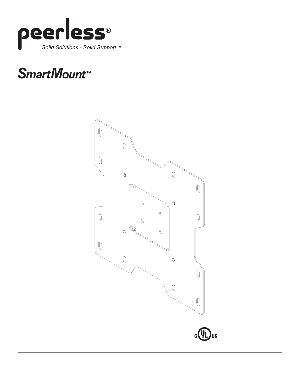
Installation and Assembly:
Universal Flat Wall Mount f or 10" - 37" LCD Flat Panel
Screens
Models: SF 635P, SF 635P-S, SF 635, SF 635-S, SF 632P, SF 632P-S, SF 632,
SF 632-S
Features:
• For 10" to 37" flat panel screens
• Ultra-slim design holds the screen flat against the wall
3215 W. North Ave. • Melrose Park, IL 60160 • (800) 729-0307 or (708) 865-8870 • Fax: (708) 865-2941 • www.peerlessmounts.com
R
Max UL Load Capacity: 115 lb (52.2 kg)
ISSUED: 04-20-05 SHEET #: 201-9429-6 02-01-06
This product is UL Listed. It must be
installed by a qualified professional
installer.
Page 2
Note: Read entire instruction sheet before you start installation and assembly.
WARNING
• Do not begin to install your Peerless product until you have read and understood the instructions and warnings
contained in this Installation Sheet. If you have any questions regarding any of the instructions or warnings, please
call Peerless customer care at 1-800-729-0307.
• This product should only be installed by a qualified professional.
• Make sure that the wall will safely support the combined load of the equipment and all attached hardware and components.
• Never exceed the Maximum UL Load Capacity of 1 15 lb (52.2 kg).
• If mounting to wood wall studs, make sure that mounting screws are anchored into the center of the studs. Use of an
"edge to edge" stud finder is highly recommended.
• Always use an assistant or mechanical lifting equipment to safely lift and position equipment.
• Tighten screws firmly , but do not overtighten. Overtightening can damage the items, greatly reducing their holding
power.
Tools Needed for Assembly
• stud finder ("edge to edge" stud finder is recommended)
• phillips screwdriver
• drill
• 1/4" bit for concrete and cinder block wall
• 5/32" bit for wood stud wall
• level
Accessories
• Metal S tud Fastener Kit (ACC 215) (Not evaluated by UL)
• Video Conferencing Shelf (ACC 309) (Not evaluated by UL)
• Accessory Shelves (PM 600, PM 610) (Not evaluated by UL)
Table of Contents
Parts List..............................................................................................................................................................................3
Installation to Single Wood Stud Wall...................................................................................................................................4
Installation to Solid Concrete or Cinder Block .......................................................................................................................5
Attaching Adapter Plate to Screen with VESA 200 or 200 x 200 Mounting Pattern ..............................................................6
Attaching Hook Bracket to Screen with VESA 75 or 100 Mounting Pattern ..........................................................................7
Installing and Removing Flat Panel Screen ...........................................................................................................................8
For customer care call (800) 729-0307 or (708) 865-8870.
2 of 8
ISSUED: 04-20-05 SHEET #: 201-9429-6 02-01-06
Page 3
3
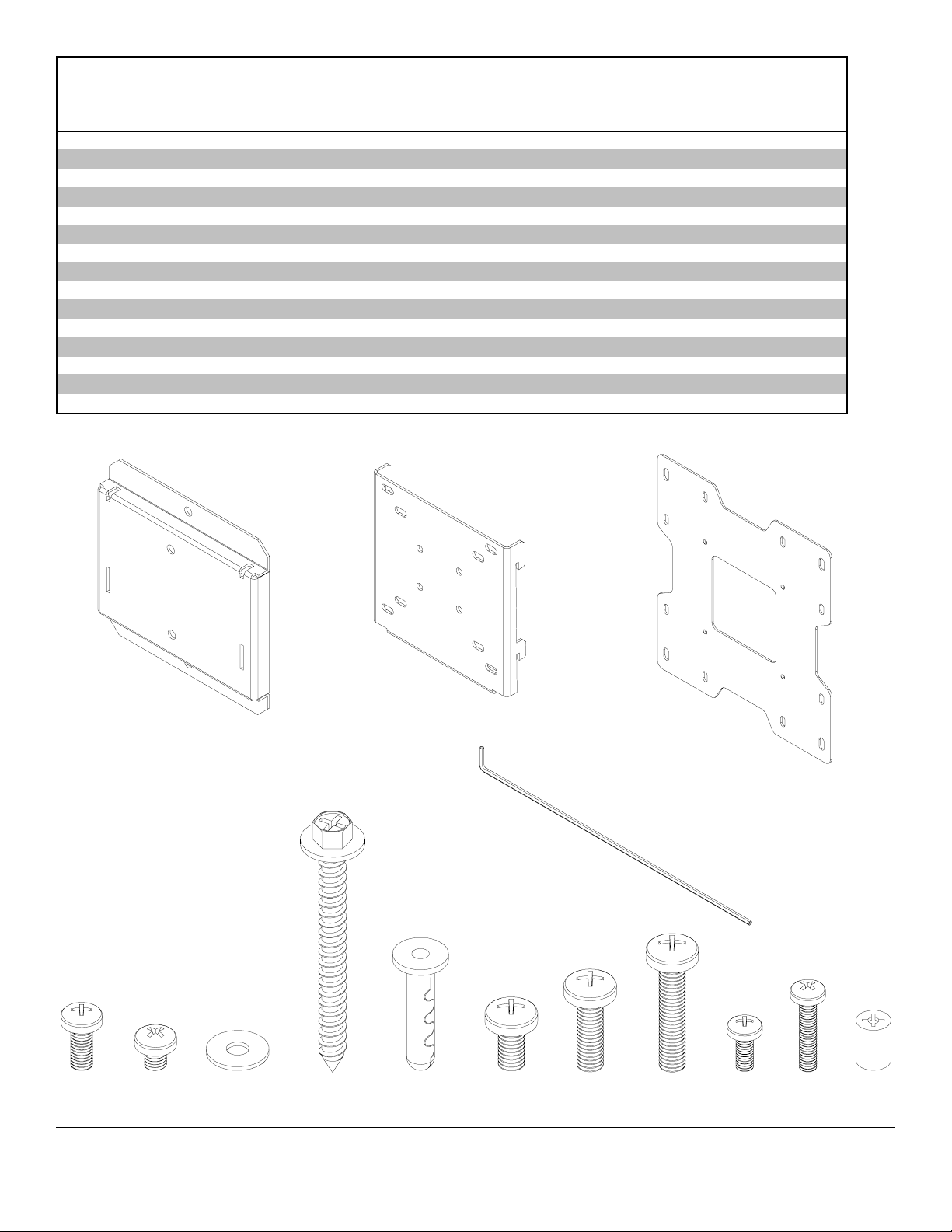
Parts L ist
De scri p tion Qty Part # Part # P art # Part #
wall plate 1 095-1320 095-4320 095-1320 095-4320
A
hook brack et 1 095-1321 095-4321 095-1321 095-4321
B
adapter plate 1 095-1322 095-4322 095-1322 095-4322
C
M5 x 12 m m s c rew 2 520-1027 520-1027 520-1064 520-1064
D
M5 x 6 m m phillips s c rew 4 520-1023 520-1023 520-1023 520-1023
E
#10 SA E was her 4 540-9400 540-9400 540-9400 540-9400
F
#14 x 2. 5" hex head wood s c rew 2 5S1-015-C03 5S1-015-C03 5S1-015-C03 5S1-015-C0
G
Alligator® anchor 2 590-0097 590-0097 590-0097 590-0097
H
M6 x 12 m m phillips s c rew 4 520-1128 520-1128 520-1128 520-1128
I
M6 x 20 m m phillips s c rew 4 520-9402 520-9402 520-9402 520-9402
J
M6 x 30 m m phillips s c rew 4 510-9109 510-9109 510-9109 510-9109
K
M4 x 10 m m phillips s c rew 4 504-9012 504-9012 504-9012 504-9012
L
M4 x 20 m m phillips s c rew 4 504-9020 504-9020 504-9020 504-9020
M
.198" ID x . 313" O D x .437" H retaining s pac er 4 590-5005 590-5005 590-5005 590-5005
N
4 mm s ec urity all en wrench 1 560-1145 560-1145
O
SF 635P , SF 635P -S , SF 635, SF 635-S ,
SF 632P SF 632P -S SF 632 SF 632-S
D
A
B
C
O
G HFE
J KLM NI
3 of 8
ISSUED: 04-20-05 SHEET #: 201-9429-6 02-01-06
Page 4

Installation to Single Wood Stud Wall
WARNING
• Make sure that the wall will safely support the combined load of the equipment and all attached hardware and
components.
Use a stud finder to locate the edges of the stud. Use of an edge-to-edge stud finder is highly recommended. Based
1
on its edges, draw a vertical line down the stud’s center . Place wall plate ( A) on wall as a template, making sure that
the two mounting holes are over the stud centerline. Level plate, and mark the center of the two holes. Drill two
5/32" (4 mm) dia. holes 2-1/2" (65 mm) deep. Make sure that the wall plate is level, secure it using two #14 x 2.5"
wood screws (G) as shown.
Skip to step 2 on page 6 for VESA 200 mm and 200 mm x 200 mm patterns.
Skip to step 2 on page 7 for VESA 75 mm and 100 mm patterns.
WARNING
• Tighten wood screws so that wall plate is firmly attached, but do not overtighten. Overtightening can damage the
screws, greatly reducing their holding power.
• Never tighten in excess of 80 in. • lb (9 N.M.).
• Make sure that mounting screws are anchored into the center of the stud. The use of an "edge to edge" stud finder is
highly recommended.
• Hardware provided is for attachment of mount through standard thickness drywall or plaster into wood studs. Installers
are responsible to provide hardware for other types of mounting situations.
G
A
4 of 8
ISSUED: 04-20-05 SHEET #: 201-9429-6 02-01-06
Page 5

Installation to Solid Concrete or Cinder Block
WARNING
• When installing Peerless wall mounts on cinder block, verify that you have a minimum of 1-3/8" of actual concrete
thickness in the hole to be used for the concrete anchors. Do not drill into mortar joints! Be sure to mount in a solid
part of the block, generally 1" minimum from the side of the block. Cinder block must meet ASTM C-90 specifications. It is suggested that a standard electric drill on slow setting is used to drill the hole instead of a hammer drill to
avoid breaking out the back of the hole when entering a void or cavity .
• Concrete must be 2000 psi density minimum. Lighter density concrete may not hold concrete anchor .
• Make sure that the wall will safely support four times the combined load of the equipment and all attached hardware
and components.
Make sure that wall plate (A) is level, use it as a
1
template to mark two mounting holes. Drill two 1/4"
(6 mm) dia. holes to a minimum depth of 2.5" (64
mm). Insert anchors (H) in holes flush with wall as
shown (right). Place wall plate over anchors and
secure with two #14 x 2.5" screws (G). Level, then
tighten all fasteners.
Skip to step 2 on page 6 for VESA 200 mm and
200 mm x 200 mm patterns.
Skip to step 2 on page 7 for VESA 75 mm and
100 mm patterns.
1
Drill holes and insert anchors (H).
2
A
concrete
surface
H
WARNING
• Tighten screws so that wall plate is firmly attached,
but do not overtighten. Overtightening can damage
screws, greatly reducing their holding power.
• Never tighten in excess of 80 in. • lb (9 N.M.).
WARNING
• Always attach concrete expansion anchors directly to
load-bearing concrete.
• Never attach concrete expansion anchors to concrete
covered with plaster, drywall, or other finishing material. If mounting to concrete surfaces covered with a
finishing surface is unavoidable, the finishing surface
must be counterbored as shown below. Be sure
concrete anchors do not pull away from concrete
when tightening screws. If plaster/drywall is thicker
than 5/8", custom fasteners must be supplied by
installer.
wall plate
CORRECT
concrete
INCORRECT
wall
plate
concrete
G
Place plate (A) over anchors (H) and secure with screws (G).
3
Tighten all fasteners.
SOLID
CONCRETE
CINDER BLOCK
H
A
G
H
CUT A WAY VIEW
plaster/
dry wall
plaster/
dry wall
5 of 8
ISSUED: 04-20-05 SHEET #: 201-9429-6 02-01-06
Page 6

Attaching Adapter Plate to Screen with VESA 200 or 200 x 200 Mounting Pattern
Note: For VESA 75 mm and 100 mm patterns, see
following page.
Thread M5 socket pin screws (D) to hook bracket (B)
2
making the screws flush with bracket as shown.
C
Attach hook bracket (B) to adapter plate (C) using
four M5 x 6 mm screws (E) and #10 washers (F) as
shown.
B
F
E
D
WARNING
• If screws don't get three complete turns in the screen inserts or if screws bottom out and adapter plate is still not
tightly secured, damage may occur to screen or product may fail.
FOR VESA 200 MOUNTING PATTERN:
3
Choose hole pattern as shown below. Attach adapter
plate (C) to back of screen using four M4 x 10 mm
screws (L) as shown below.
*Note: If screw (L) gets less than three threads of
engagement, attach adapter plate (C) to back of
screen using four M4 x 20 mm screws (M) and four
spacers (N) as indicated below.
Skip to step 4 on page 8.
FOR VESA 200 x 200 MOUNTING PATTERN:
Choose hole pattern as shown below. Attach adapter
plate (C) to back of screen using four M6 x 12 mm
screws (I) as shown below.
*Note: If screw (I) gets less than three threads of
engagement, attach adapter plate (C) to back of
screen using four M6 x 20 mm screws (J). If screw
(J) still gets less than three threads of engagement,
use four M6 x 30 mm screws (K).
Skip to step 4 on page 8.
C
L
*For screens with a hole
pattern in a pocket,
spacers (N) go between
adapter plate (C) and
screen.
M
N
6 of 8
C
I
ISSUED: 04-20-05 SHEET #: 201-9429-6 02-01-06
Page 7

Attaching Hook Bracket to Screen with VESA 75 or 100 Mounting Pattern
Thread M5 phillips screws (D) to hook bracket (B)
2
making the screws flush with bracket as shown in
figures 2.1 and 2.2.
B
B
D
fig. 2.1
fig. 2.2
D
WARNING
• If screws don't get three complete turns in the screen inserts or if screws bottom out and bracket is still not tightly
secured, damage may occur to screen or product may fail.
FOR VESA 75 MOUNTING PATTERN:
3
Choose hole pattern as shown below. Attach hook
bracket (B) to back of screen using four M4 x 10 mm
screws (L) as shown below.
*Note: If hole pattern is in a pocket, attach hook
bracket (B) to back of screen using four M4 x 20 mm
screws (M) and four spacers (N) as indicated below.
B
FOR VESA 100 MOUNTING PATTERN:
Choose hole pattern as shown below. Attach hook
bracket (B) to back of screen using four M4 x 10 mm
screws (L) as shown below.
L
*For screens with a hole
pattern in a pocket,
spacers (N) go between
hook bracket (B) and
screen.
N
M
7 of 8
B
L
ISSUED: 04-20-05 SHEET #: 201-9429-6 02-01-06
Page 8

Installing and Removing Flat Panel Screen
Hook screen onto wall plate (A) figure 4.1. Tighten
4
M5 x 12 mm screws (D), shown in figure 4.2 and
detail 1.
Note: For security models, use 4 mm security allen
wrench (O) to tighten M5 x 12 mm screws (D).
T o remove screen from mount, loosen screws (D)
and lift screen off of mount.
WARNING
• Do not lift more weight than you can handle. Use
additional man power or mechanical lifting equipment
to safely handle placement of the screen.
• Failure to lock hook bracket with screws (D) can
cause screen to come off mount if hit accidentally.
CAUTION
• Do not tighten screws with excessive force.
Overtightening can cause damage to mount. Tighten
screws to 20 in. • lb (2.26 N.M.) maximum torque.
SCREEN
A
fig. 4.1
B
D
fig. 4.2
A
A
B
D
DETAIL 1
8 of 8
All other brand and product names are trademarks or registered trademarks of their respective owners.
ISSUED: 04-20-05 SHEET #: 201-9429-6 02-01-06
© 2005 Peerless Industries, Inc. All rights reserved.
Peerless is a registered trademark of Peerless Industries, Inc.
 Loading...